


VIVIX Setup Operation Manual
© Vieworks. 2023 All rights reserved.
Under copyright laws, this manual should not be reproduced, in whole or in part, without the written
permission of Vieworks.
The specifications and related information in this manual may be changed without notice. Refer to Vieworks
Download System (VDS) for the latest version of our manuals. This document is basically produced in English
and can be produced in the language of the relevant country upon request of the customer.

VIVIX Setup Operation Manual
Contents
1. Instruction ......................................................................................................................................... 6
1.1 Precautions ............................................................................................................................................... 7
1.2 Document Guide ..................................................................................................................................... 8
1.2.1 Document Contents ..................................................................................................................................................... 8
1.2.2 Symbols .............................................................................................................................................................................. 8
1.2.3 Notations ........................................................................................................................................................................... 8
1.2.4 Contact Us ........................................................................................................................................................................ 9
1.2.5 Revision History ............................................................................................................................................................10
2. Installation ....................................................................................................................................... 13
2.1 Getting Started ...................................................................................................................................... 14
2.1.1 Preparing to Install VIVIX Setup ...........................................................................................................................14
2.1.2 Recommended Specifications ................................................................................................................................14
2.1.3 Supported Models ......................................................................................................................................................15
2.1.4 Installation Components ..........................................................................................................................................15
2.1.5 Installation Steps ..........................................................................................................................................................15
2.2 Installing VwFilter ................................................................................................................................. 16
2.3 Setting Windows Environment ........................................................................................................... 17
2.3.1 Setting Network Adapter .........................................................................................................................................17
2.3.2 Disabling Sleep Mode of Monitor .......................................................................................................................21
2.3.3 Firewall Settings............................................................................................................................................................22
3. Settings ............................................................................................................................................ 26
3.1 Getting Started ...................................................................................................................................... 27
3.2 Checking Devices (Discovery Dialog) ................................................................................................ 28
3.2.1 Status Information .......................................................................................................................................................28
3.2.2 SCU .....................................................................................................................................................................................28
3.2.3 Detectors .........................................................................................................................................................................29
3.2.4 Admin Mode ..................................................................................................................................................................30
3.2.5 Buttons..............................................................................................................................................................................31
3.3 Getting into the Device (Main Dialog).............................................................................................. 32
3.3.1 Information Display ....................................................................................................................................................32
3.3.2 Buttons..............................................................................................................................................................................32
3.4 SCU Configuration Dialog ................................................................................................................... 33
3.4.1 System ...............................................................................................................................................................................33
3.4.2 Network ............................................................................................................................................................................34
Rev.1.1.12 Page 2 of 114 VW40-15A-003

VIVIX Setup Operation Manual
3.4.3 AP (Access Point) .........................................................................................................................................................35
3.4.4 Trigger ...............................................................................................................................................................................37
3.4.5 Tes t M od e ........................................................................................................................................................................38
3.4.6 Order Buttons ................................................................................................................................................................39
3.5 Detector Configuration Dialog ........................................................................................................... 40
3.5.1 Network ............................................................................................................................................................................41
3.5.2 WNetwork .......................................................................................................................................................................41
3.5.3 AP (Access Point) .........................................................................................................................................................42
3.5.4 Power Mode (Power Management) ....................................................................................................................44
3.5.5 Exposure Mode .............................................................................................................................................................47
3.5.6 Auto Offset Refresh Setting ....................................................................................................................................47
3.5.7 Image (Image Timeout) ............................................................................................................................................48
3.5.8 User Input Direction ...................................................................................................................................................49
3.5.9 Inter Packet Delay ........................................................................................................................................................49
3.5.10 Buttons..............................................................................................................................................................................49
3.6 Preset Configuration............................................................................................................................. 51
3.6.1 Setting the Preset List ...............................................................................................................................................51
3.6.2 Setting the Individual Preset Item .......................................................................................................................52
4. Calibration ....................................................................................................................................... 53
4.1 Calibration Guide .................................................................................................................................. 54
4.2 Calibration Dialog ................................................................................................................................. 55
4.2.1 How to Use .....................................................................................................................................................................55
4.2.2 Menu .................................................................................................................................................................................56
4.3 System Configuration ........................................................................................................................... 57
4.3.1 Exposure Timing ...........................................................................................................................................................57
4.3.2 Digital Offset ..................................................................................................................................................................59
4.3.3 Gain Type .........................................................................................................................................................................59
4.3.4 Smart W ...........................................................................................................................................................................60
4.4 Drive Mode ............................................................................................................................................. 61
4.4.1 Drive Mode List ............................................................................................................................................................62
4.4.2 Drive Mode Setting ....................................................................................................................................................63
4.4.3 Fluoroscopy Setting ....................................................................................................................................................64
4.5 Offset Calibration .................................................................................................................................. 65
4.5.1 Offset Calibration Functions ...................................................................................................................................65
4.5.2 Calibrating by Loading Offset Data ....................................................................................................................66
4.5.3 Calibrating by Generating Offset Data ..............................................................................................................66
4.6 Gain Calibration ..................................................................................................................................... 67
4.6.1 Gain Calibration Functions ......................................................................................................................................67
Rev.1.1.12 Page 3 of 114 VW40-15A-003

VIVIX Setup Operation Manual
4.6.2 Calibrating by Loading Gain Data .......................................................................................................................68
4.6.3 Calibrating by Generating Gain Data .................................................................................................................69
4.6.4 Gain Compensation ....................................................................................................................................................70
4.6.5 Managing Partial Gain Data ...................................................................................................................................71
4.7 Defect Calibration ................................................................................................................................. 73
4.7.1 Defect Calibration Functions ..................................................................................................................................73
4.7.2 Calibrating by Loading the Defect Data ...........................................................................................................74
4.7.3 Calibrating by Generating Defect Data with Auto Defect Correction ................................................75
4.7.4 Calibrating by Generating Defect Data with Manual Defect Correction ...........................................78
4.8 Acceleration Sensor .............................................................................................................................. 81
4.9 Detector Configuration ........................................................................................................................ 83
4.9.1 Detector Configuration Functions........................................................................................................................83
4.9.2 Detector Configuration Buttons ............................................................................................................................85
4.10 AEC Calibration .................................................................................................................................. 86
4.10.1 AEC Calibration Functions .......................................................................................................................................86
4.10.2 Tools for Image Adjusment .....................................................................................................................................87
5. Image Diagnosis and Product Maintenance ............................................................................ 88
5.1 Image Diagnosis .................................................................................................................................... 89
5.1.1 Image Adjustment Tools...........................................................................................................................................90
5.1.2 Information Display Items .......................................................................................................................................90
5.1.3 Button Tools ...................................................................................................................................................................92
5.1.4 Importing the Backup and Stored Images ......................................................................................................93
5.1.5 Fast Tact-Time Mode (FTM) ....................................................................................................................................94
5.2 Detector Maintenance .......................................................................................................................... 96
5.2.1 System Information .....................................................................................................................................................97
5.2.2 Log Download ...............................................................................................................................................................99
5.2.3 Temperature ................................................................................................................................................................ 100
5.2.4 Checking Detector State ........................................................................................................................................ 100
5.2.5 Total Shot Count ....................................................................................................................................................... 100
5.2.6 Performance Test....................................................................................................................................................... 101
5.2.7 Checking Communication Status ...................................................................................................................... 102
5.2.8 Battery Diagnosis ...................................................................................................................................................... 103
5.2.9 Changing Tag Information of NFC Card ........................................................................................................ 105
5.2.10 Factory Reset .............................................................................................................................................................. 107
5.2.11 Self Diagnosis ............................................................................................................................................................. 107
5.3 SCU Diagnosis ...................................................................................................................................... 109
6. Appendix........................................................................................................................................ 110
Rev.1.1.12 Page 4 of 114 VW40-15A-003

VIVIX Setup Operation Manual
6.1 Offset Stabilization Function (OSF) ................................................................................................. 111
6.1.1 Ter ms .............................................................................................................................................................................. 111
6.1.2 Terms of Use ............................................................................................................................................................... 111
6.1.3 How to Use .................................................................................................................................................................. 112
6.1.4 Data for Reference ................................................................................................................................................... 113
Rev.1.1.12 Page 5 of 114 VW40-15A-003

VIVIX Setup Operation Manual
1. Instruction
This section gives basic information of this manual and products.
Precautions
Document Guide
Document Convention
Version Information
Revision History
Rev.1.1.12 Page 6 of 114 VW40-15A-003
1.1 Precautions
If the user is not fully acquainted with this manual, the product can be malfunctioned, or unsuspected
problem can be happened due to carelessness. To prevent any medical accidents, the user should fully
understand the instructions of this manual before operating this program.
When users operate VIVIX Setup, take the following precautions. Otherwise, problems may occur, or the
product may not function correctly.
1 Roentgenography, image processing, reading of image, and data storage must be performed in
accordance with the law of each country where the program is being used.
2 The user is responsible for protecting the privacy of image data.
3 Before using this program, be sure to read this manual thoroughly. Also, read other manuals of relevant
equipment in the system. Keep this manual where is easily accessible.
VIVIX Setup Operation Manual
Make sure to do the detector calibration with VIVIX Setup before using the products.
Refer to the contents in this manual for the details about detector calibration.
Rev.1.1.12 Page 7 of 114 VW40-15A-003
1.2 Document Guide
This manual is intended for service engineers who install and manage VIVIX-S detectors and VIVIX Setup.
1.2.1 Document Contents
This manual offers guidance about various functions of VIVIX Setup. With this program, the user can set
and calibrate detectors / SCU, as well as check products for defects thorough the diagnosis function.
1.2.2 Symbols
Warning and Caution
This symbol is used to indicate a potentially hazardous situation that may cause death,
personal injury or substantial property damage if the instructions are ignored. Users
should be well acquainted with this symbol and the related contents.
VIVIX Setup Operation Manual
Information
1.2.3 Notations
Bold Types
Words in bold indicate products terms, or the sentences which are needed to transmit clear meaning to the
customers
This symbol is used for indicating product related references and supplementary
information. Users are recommended to read the sentences with this notice carefully.
Rev.1.1.12 Page 8 of 114 VW40-15A-003
Item Contents
Department
Customer Support Team at Vieworks
E
CustomerSupport@vieworks.com
1.2.4 Contact Us
This manual is provided in print format upon request by the customer.
For comments or inquiries regarding this document and relevant products, contact via email below:
VIVIX Setup Operation Manual
-mail
You can download this manual from VDS (Vieworks Download System) website:
https://clouds.vieworks.com:5001/. To obtain an ID and password for manual download,
please contact the customer support team in Vieworks.
Rev.1.1.12 Page 9 of 114 VW40-15A-003

Ver. Date
Revision History
4.3 2015
Initial Release
4.4 2015
(Added)
4.8 2016
(Changed)
(Changed) 4.5 Gain Calibration
(Changed) 4.7 Detector Configuration
4.
20
(Added) 2.1.4
(
4.11 20
(Added)
(
V4.11
4.14 2016
(Added)
(Added) 2.1.4
-
(Added) 2.2 Installing VIVIX Device Driver (VDD)
(Changed) 4.2 Calibration Dialog
-
(Added) 4.5.2
-
(Changed) 4.7.1 Detector Configuration Functions
-
4
20
(C
-
4.23 2017
(
(
(
(
-
(
Maintenance
(
(
1.0.5
2017
(Added
(Ad
(Added) 3.2.3 Detectors
(Added) 3.4.4 Trigger
1.2.5 Revision History
VIVIX Setup Operation Manual
10
-10-07
-10-29
-02-26
16-04-08
16-07-26
-10-31
2.1.4 Version Compatibility (Recommended)
3.5 Detector Configuration Dialog
Version Compatibility (Recommended)
Added) 3.5 Detector Configuration Dialog
6.2 OSF
Changed) Updated UI images and functional descrition of VIVIX Setup
2.1.2 Recommended Specifications - Warnings
Version Compatibility (Recommended)
Compatibility for VIVIX Setup V1.0.4.14
- Warnings
Screen image as removing ‘Pre-Exposure Section’ menu of VIVIX Setup.
Calibrating by Loading Gain Data
Additional information
Additional information
.15
Rev.1.1.12 Page 10 of 114 VW40-15A-003
16-11-23
-04-13
-08-16
hanged) 2.1.4 Version Compatibility (Recommended)
Added compatible versions by updating VIVIX Setup to V1.0.4.15
Changed) The name of ‘Diagnosis’ window to ‘Maintenance’
Added) Descriptions for adding information of FXRD-1417N detector
Added) 2.1.3 Supporting Model
- Adding FXRD-1417N detector
Changed) 2.1.4 Version Compatibility (Recommended)
Adding compatible version as updating VIVIX Setup V1.0.4.23
Changed) 3.5 Detector Configuration, 4 Calibration, 5.2 Detector
- Changing user interface images for the changes of each window item
Changed) 5.1.3 Button Tools
- Changing sentences related to the setting of image direction
Changed) 6.2.2 Conditions of Use
- Changing conditions for using OSF
) Instructions on adding FXRD-1717V
ded) 2.1.3 Support Model - FXRD-1717V

(Change
Generat
-
(Added) 5.1 Image Diagnosis
-
(Added
(Change
1
2017
(
(Added
(Added
(
1012T
1.0.7
2017
R
consequential
damages arising from the use or unavailability of this product
Changed
Changed the
1.0.8 2018
(
-
(Changed) 4.3.3 Gain type
-
1.0.9
2018
(
-
(
-
1.0.10
2018
(Added) 2.1.3
(Changed) 2.1.4
-
(Added) 6.1
-
(Changed) 6.2.2
-
1
2018
(Changed) 2.1.4
-
1
2
(Changed) 2.1.4
-
(
(
1
2019
(Changed) 2.1.4
-
(Modified) References in chapter 3
VIVIX Setup Operation Manual
d) 4.5.2 Calibrating by Loading Gain Data / 4.5.3 Calibrating by
ing Gain Data
Correcting contents related to 1717V
Adding description based on the addition of the Packet Trigger
) 6.1 Supportable list by detector model - FXRD-1717V model
d) 6.2.2 Terms of Use – Added contents related to FXRD-1717V
Added) Addition of instructions related to FXRD-1012T model.
) 2.1.3 Supporting Model - FXRD-1012T
.0.6
-09-20
-12-18
) 2.1.4 Version Compatibility (Recommended) - FXRD-1012T
Changed) 6.2.2 Conditions of Use - Changed contents related to FXRD-
emoved the following sentence in chapter 1.1 ‘Precautions’.
- In no event shall Vieworks be liable for direct or indirect
.
2.1.4 Version Compatibility (Recommended)
- Added compatible versions according to VIVIX Setup V1.0.7 update.
European agent address and contact information.
Changed) 2.1.4 Version Compatibility (Recommended)
-01-15
.0.11
.0.15
Rev.1.1.12 Page 11 of 114 VW40-15A-003
.0.17
-05-30
-07-16
-09-18
019-03-20
-12-10
Added compatible versions for VIVIX Setup V1.0.8 update
Updated sensitivity of each detector type and gain type
Changed) 2.1.4 Version Compatibility (Recommended)
Added compatible versions for VIVIX Setup V1.0.9 update
Added) 5.1 Image Diagnosis
Added instructions of progress bar
Added compatible version for VIVIX Setup V1.0.10 update
FXRD-1717V
Added instructions related to FXRD-1717V
Added compatible version for VIVIX Setup V1.0.11 update
Added compatible version for VIVIX Setup V1.0.15 update
Added) 2.2 Installing VwFilter
Changed) 5.1 Image Diagnosis – User interface of the Image window
Added compatible version for VIVIX Setup V1.0.17 update
Supported Models - VXTD-2532E
Version Compatibility (Recommended)
List of Support Functions for each Detector Model
Terms of Use
Version Compatibility (Recommended)
Version Compatibility (Recommended)
Version Compatibility (Recommended)
Settings and chapter 4 Calibration

1
2
(
(
(
1
2
(R
(
(
1
2
(
1
2
(C
(
(
1
2
(C
(
(
1
2
(
1
2
(
(
(
(A
1
2
(
1
2
(Changed) Document version
1
2
(Changed) Document version
1
2
(
(
(
(
(
(
1
2
(
(
1
2
(
Defect Correction
(Changed)
(A
1
2
(
1
2
(
:
(
(Changed)
(Changed)
: Added reference
1
2
(
VIVIX Setup Operation Manual
Changed) 2.1.2 Recommended Specifications
.0.18
.0.19
020-04-03
020-07-21
Removed) 2.1.4 Version Compatibility (Recommended)
Added) 4.7 Detector Configuration – UI and description of MSC
emoved) 4.7 Detector Configuration – removed E.A button
Changed) 5.1.1 Image Adjustment Tools – changed the name of tools
Added) 5.1.3 Button Tools – added Auto Exp Start/Stop
.0.22
.0.23
.0.25
.1.0
.1.2
.1.3
.1.4
.1.5
.1.6
020-08-27
020-11-16
021-04-02
021-10-18
022-01-27
022-03-19
022-03-24
022-06-10
022-10-17
Changed) Document file version
hanged) 3.2.3 Detectors – changed the notice of IP change
Added) 4. Calibration – information on calibration of acceleration sensor
Added) Production plant address
hanged) 1.2.4 Contact Us
Changed) Sentence on the cover
Changed) Production plant address
Changed) Document file version
Added) 3.5.5 Detector models that support drive mode
Added) 4.3.3 Detector models that support drive mode
Added) 4.4 Drive Mode
dded) 4.6.4 Gain Compensation
Changed) Document version
Changed) 2.1.2 Recommended Specifications
Added) 4.3.4 Smart W
Changed) 4.4 Drive Mode
Changed) 4.4.2 Drive Mode Setting
Deleted) 4.4.3 Multi Frame Setting
Added) 4.4.3 Fluoroscopy Setting
.1.7
.1.9
.1.10
.1.11
Rev.1.1.12 Page 12 of 114 VW40-15A-003
.1.12
023-03-09
023-06-20
023-07-24
023-09-18
023-11-28
Changed) 2.3.3 Firewall Settings
Changed) 4.3.4 Smart W
Changed) 4.7.4 Calibrating by Generating Defect Data with Manual
4.9.1 Detector Configuration Functions
dded) 4.0 AEC Calibration
Changed) 5.2.8 Battery Diagnosis
Changed) 2.1.2 Recommended Specifications
Supports Microsoft Windows 11
Changed) 2.3.1 Setting Network Adapter
2.3.3 Firewall Settings
5.2.1 System Information
s
Changed) 4.10.1 AEC Calibration

VIVIX Setup Operation Manual
2. Installation
This chapter explains about the basic concept, recommended specifications, and installation of
VIVIX Setup.
Preparing to Install VIVIX Setup
Installing VwFilter
Setting Windows Environments
Rev.1.1.12 Page 13 of 114 VW40-15A-003

Components
Minimum Spec.
Recommended Spec.
OS M
LAN Card
Gigabit supported LAN card for network
CPU
Intel® Core
(
Intel® Core
(
Memory
4GB 16GB or more
HDD or SSD
1TB 2TB or more
Monitor
General monitor: 1280 x 800
1920 x 1080, 2560 x
CD
CD or DVD Reader / Writer
2.1 Getting Started
2.1.1 Preparing to Install VIVIX Setup
VIVIX Setup provides various functions such as setting, calibration, and self-diagnosis for operating the
VIVIX-S detector models and SCU made by Vieworks.
Checks the setting status of VIVIX-S detectors and SCU.
Upgrades VIVIX-S detectors and SCU.
Configures wired / wireless network of VIVIX-S detectors and SCU.
Calibrates VIVIX-S detectors.
Checks images acquired from VIVIX-S detectors,
Performs Self-diagnosis of VIVIX-S detectors and SCU.
2.1.2 Recommended Specifications
VIVIX Setup Operation Manual
-ROM
icrosoft Windows 10 Professional (64bit) Microsoft Windows 11 Professional (64bit)
Gigabit Ethernet card for
detector interface (Intel® Series)
Speed: 1Gbps or higher
Jumbo Frames: 9K
Receive Descriptors: 1024
802.11ac (Wireless)
LAN card for network interface
1000BASE-T Gigabit Ethernet card for
detector interface (Intel® I210 Series,
I350 Series)
Speed: 1Gbps or higher
Jumbo Frames: 9K
Receive Descriptors: 2K or more.
802.11ac (Wireless)
(optional)
™ i5 8400-CPU
Or compatible CPU)
interface (optional)
™ i9 11900-CPU or higher
Or compatible CPU)
General monitor:
Surface pro 4 : 2160 x 1440
1440
Rev.1.1.12 Page 14 of 114 VW40-15A-003
After January 14, 2020, Microsoft will no longer provide security updates or support for
PCs running Windows 7. As this increases your chances of getting infected with new
viruses or malware, we recommend upgrading to Windows 10, which continues to offer
security updates.
Before you start running VIVIX Setup, make sure to check if Visual C++ Redistributable
for Visual Studio 2015 is installed in your PC.
Category
Model
Detector
SCU
Components
Description
V
N
VIVIX
A p
2.1.3 Supported Models
VIVIX Setup Operation Manual
FXRD-1717S / FXRD-1417S / FXRD-1717V
FXRD-1417W
FXRD-1012N / FXRD-1417N / FXRD-1717N
VXTD-2532E
FXRD-2530VW / FXRD-3643VW / FXRD-4343VW
FXRS-02A, FXRS-03A, FXRS-04A
2.1.4 Installation Components
wFilter
Setup
etwork filter driver for getting images quickly. (For Vieworks’ detectors only)
rogram for setting and managing the detector and SCU.
2.1.5 Installation Steps
1 Install VwFilter.
2 Set Windows and network environment.
3 Locate VIVIX Setup in the proper route and execute it.
Follow the installation steps in sequence to install the program correctly.
Rev.1.1.12 Page 15 of 114 VW40-15A-003

2.2 Installing VwFilter
For information on installing VwFilter, refer to the VwFilter Driver Installation Guide.
VIVIX Setup Operation Manual
Rev.1.1.12 Page 16 of 114 VW40-15A-003
2.3 Setting Windows Environment
This chapter instructs on how to set Windows environment for communicating with the detector and SCU.
The configuration may be different with this manual depending on the manufacturers or
models of the network adapter.
If Windows environment is not configured properly, a communication error may occur
between detector / SCU and workstation, and it can have a serious effect on the products
and image quality.
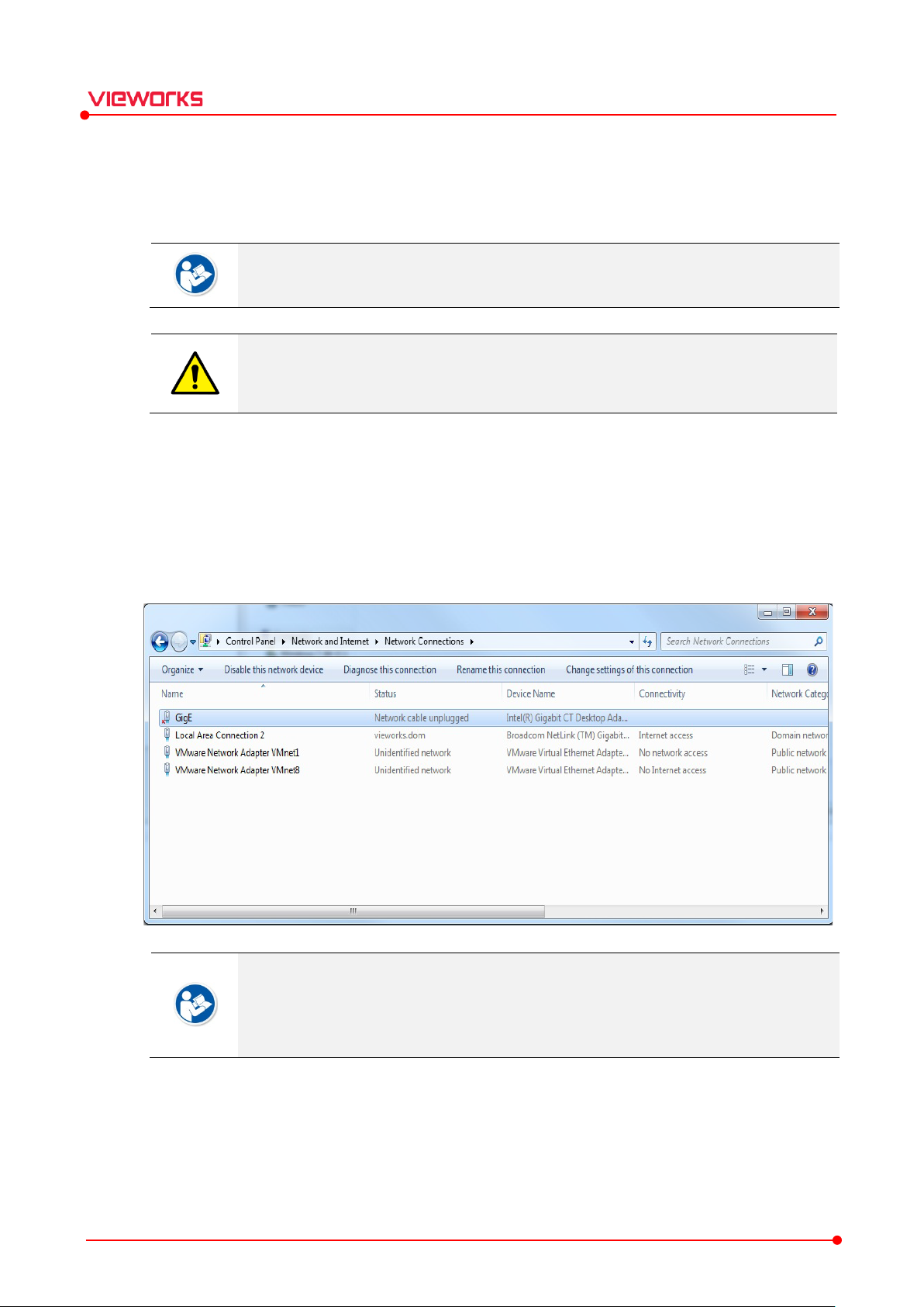
2.3.1 Setting Network Adapter
1 Move to Start Control Panel Network and Internet Network and Sharing Center Change
Adapter Setting.
2 Choose the network adapter to communicate with the detector and SCU, and change its name.
VIVIX Setup Operation Manual
It is recommended to change the network adapter name to distinguish it from other
names.
The changed name cannot affect operation of the equipment and communication
performance.
3 Right click the selected network adapter and choose Properties.
4 Click Configure button to open the dialog box, and move to the Advanced tab.
Rev.1.1.12 Page 17 of 114 VW40-15A-003
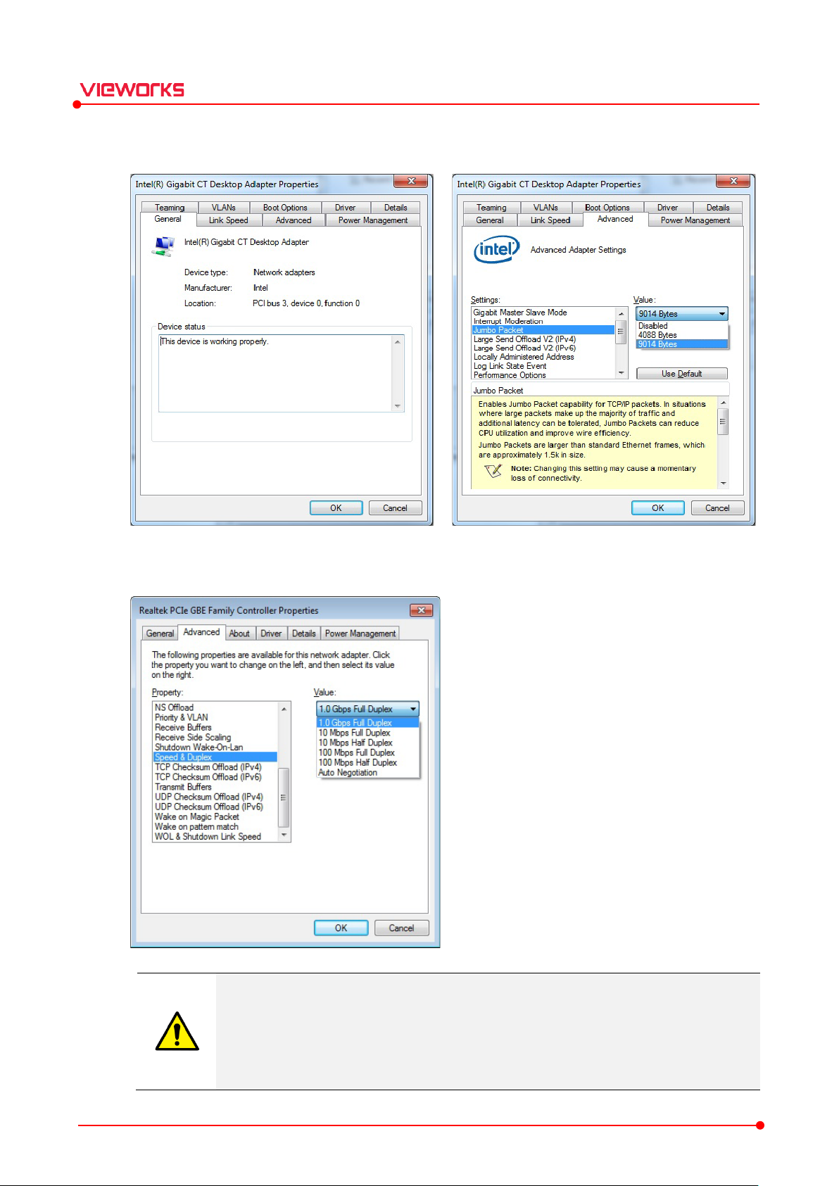
If you
VIVIX Setup Operation Manual
5 Set Jumbo Packet to its maximum value. (Recommended value: 9014 bytes)
6 Set Speed & Duplex to its maximum value, 1.0 Gbps Full Duplex.
Be sure to set Speed & Duplex to 1.0 Gbps Full Duplex to receive bulk image data.
set the item under 100 Mbps, it seriously affects image quality, or you cannot acquire
images.
It is recommended not to choose Auto Negotiation. The network adapter can be
Rev.1.1.12 Page 18 of 114 VW40-15A-003
communicated with a detector and SCU at a speed of 100Mbps if you choose the item.
VIVIX Setup Operation Manual
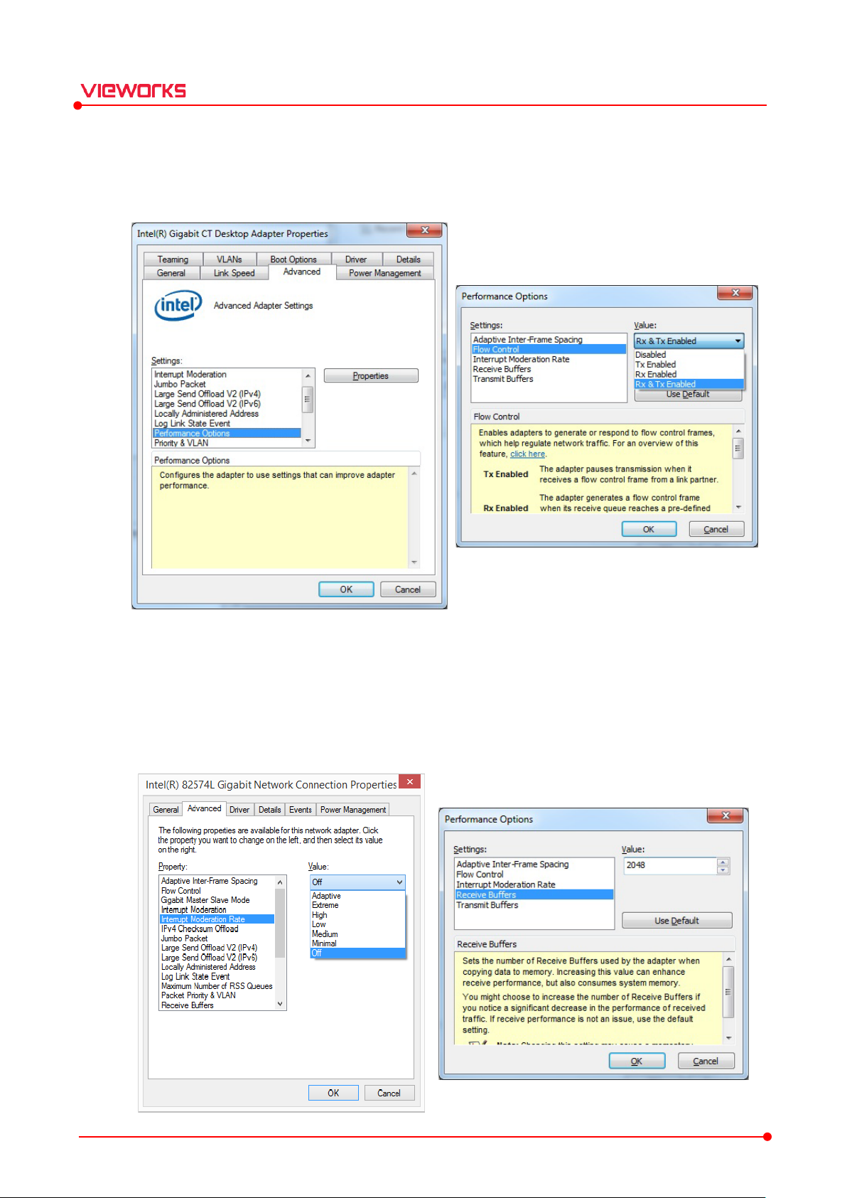
7 Choose Performance Options in the list of Settings and click Properties button on the right.
8 Choose Flow Control in the list of Settings and select Rx & Tx Enabled on the Valu e list.
9 Choose Interrupt Moderation Rate in the list of Settings and select Off on the Val ue list.
10 Choose Receive Buffers and set it to the maximum value.
11 Click OK button.
Rev.1.1.12 Page 19 of 114 VW40-15A-003
VIVIX Setup Operation Manual
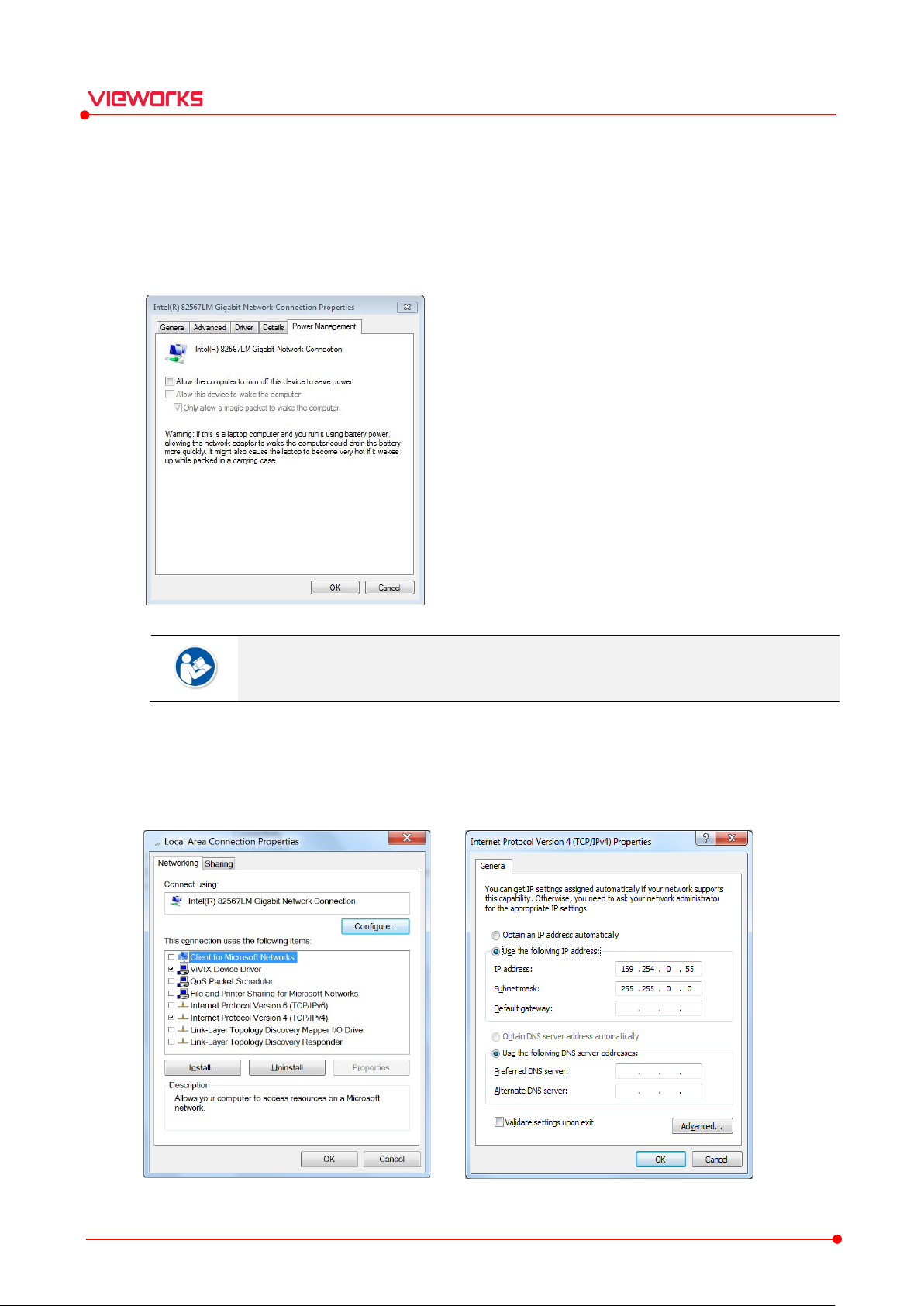
12 Click the Power Management tab and uncheck Allow the computer to turn off this device to save
power. Then click OK button.
Deactivate the power save mode of all the installed network adaptors. If not, the network
adapter will not be operated normally and it can affect the operation of equipment.
13 Choose Internet Protocol Version 4 (TCP/IPv4).and click Properties button.
14 Input the IP address and subnet mask as shown below, and then click OK button.
Rev.1.1.12 Page 20 of 114 VW40-15A-003
Item Value
Jumbo Packet
Maximum or 9014 Bytes
Flow Control
Rx & Tx Enabled
Interrupt Moderation Rate
O
Receive Buffers
Maximum
Speed & Duplex
1.0
Allow the computer to turn off this device to save power
Unchecked
IP Address
169.254.0.(50 ~ 254)
Subnet Mask
255.255.0.0
VIVIX Setup Operation Manual
It is recommended to uncheck the other items on the list except for VIVIX Device Driver
and Internet Protocol Version 4(TCP/IPv4), since they are not related with the detector
communication.
Summary of Network Configuration
It is recommended to set the IP address and subnet mask within the range presented in
this document.
If you use IP address and subnet mask out of the suggested range, it could be difficult to
identify and resolve the cause of communication disorder.
If it is necessary to use switching hub to connect more than two detectors, choose the
hub which specification is same as that of a LAN card. In case the specification is lower
than that of a LAN card, errors in communication or image could happen.
ff
Gbps Full Duplex
It is recommended to use the UTP network cable within 50m. (Supported cable: CAT5E
and CAT6)
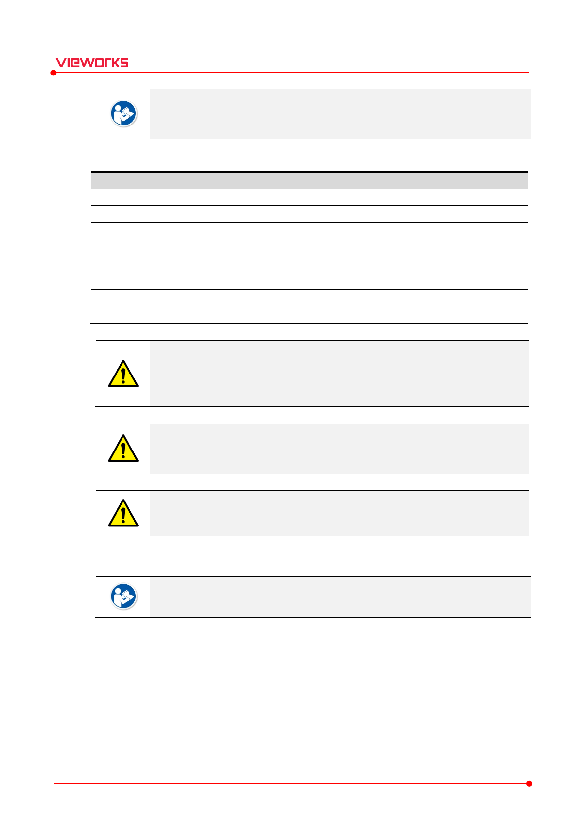
2.3.2 Disabling Sleep Mode of Monitor
If you use the sleep mode, the VIVIX Setup or VXvue program may not work normally.
1 Move to Start Control Panel Power Options and select the Choose when to turn off the display
tab.
2 Set Put the computer to sleep to Never to disable the sleep mode.
3 Click the Save changes button.
Rev.1.1.12 Page 21 of 114 VW40-15A-003
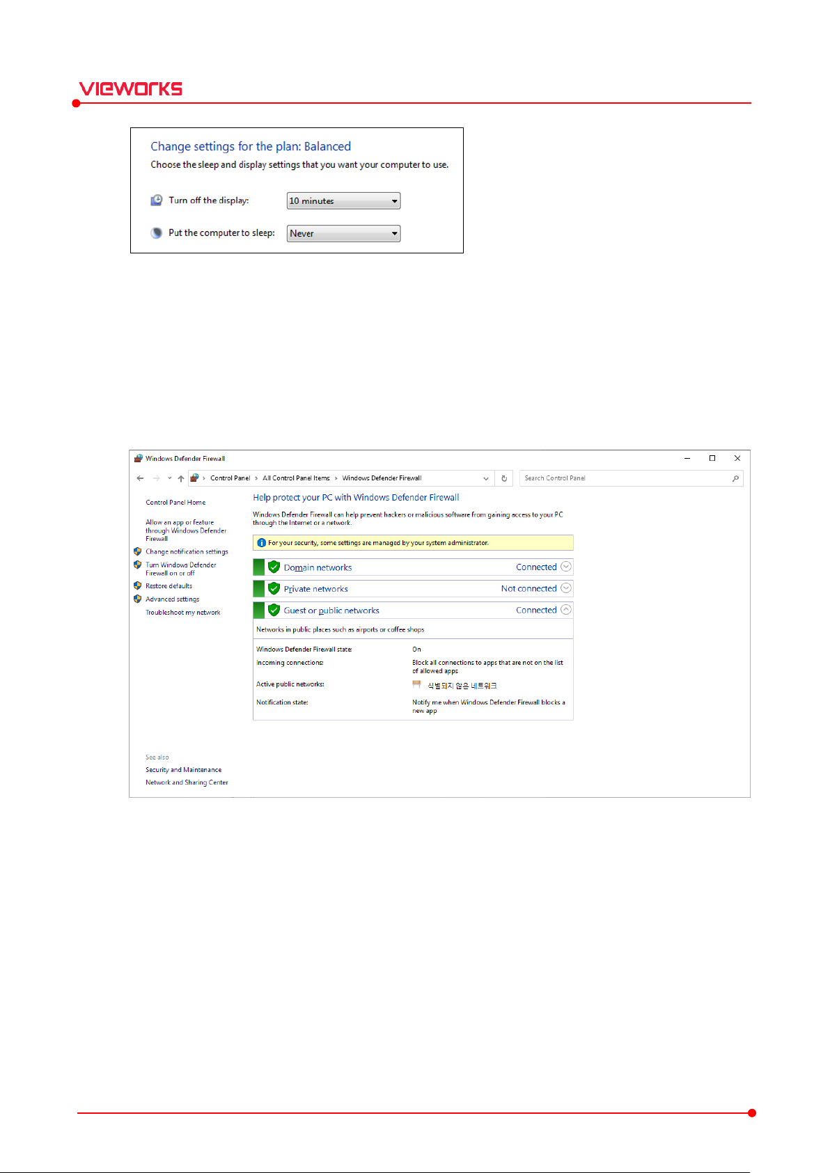
2.3.3 Firewall Settings
1 Move to Start Control Panel Windows Firewall.
2 Select Allow an app or feature through Windows Defender Firewall (Allow a program or feature
through Windows Firewall) from the left menu.
VIVIX Setup Operation Manual
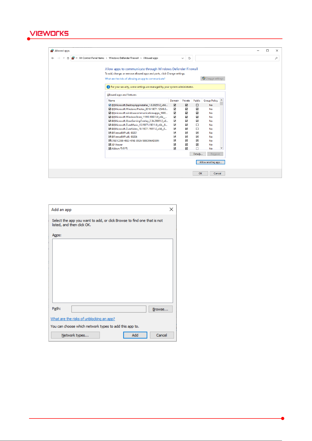
3 Click the Allow another app (Allow another program) button to check if VIVIX Setup is registered in
the list.
Rev.1.1.12 Page 22 of 114 VW40-15A-003
VIVIX Setup Operation Manual
4 If it is not registered in the list, click the Browse button for manual registration.
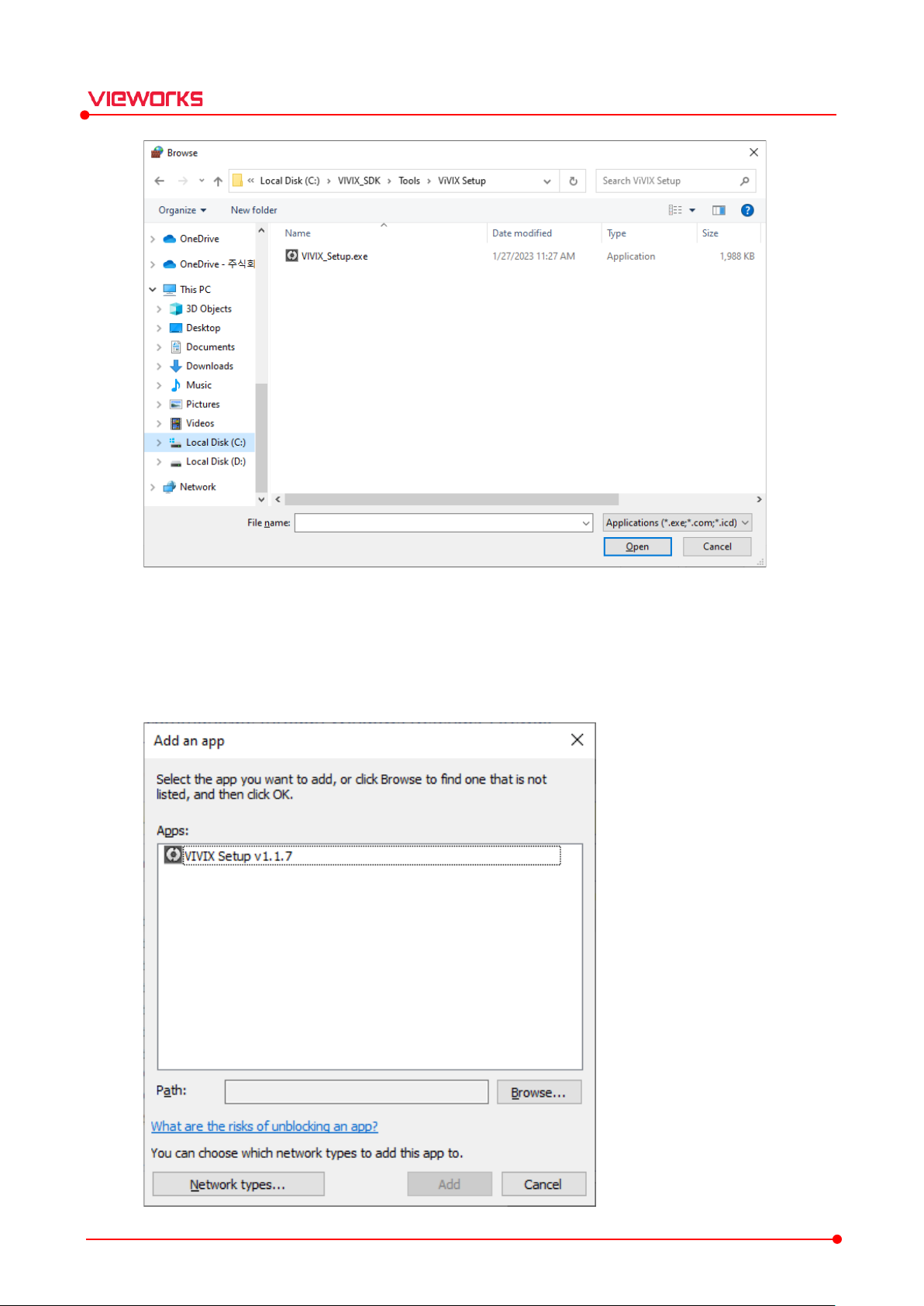
5 Go to the installation path (C:\VIVIX_SDK\Tools\ViVIX Setup), select the VIVIX_Setup.exe file and click
the Open button.
Rev.1.1.12 Page 23 of 114 VW40-15A-003
VIVIX Setup Operation Manual
6 Select the VIVIX_Setup.exe file and click the Add button.
Rev.1.1.12 Page 24 of 114 VW40-15A-003

VIVIX Setup Operation Manual
If you do not set the Windows Firewall, communication with the detector may not be
possible.
Rev.1.1.12 Page 25 of 114 VW40-15A-003

VIVIX Setup Operation Manual
3. Settings
This chapter explains about the composition of VIVIX Setup program.
Getting Started
Checking Devices (Discovery Dialog)
Getting into the Device (Main Dialog)
SCU Configuration Dialog
Detector Configuration Dialog
Rev.1.1.12 Page 26 of 114 VW40-15A-003
3.1 Getting Started
You can run the VIVIX Setup program by double-clicking its execution file without any installation process.
1 Decompress the VIVIX Setup 1.0.X.zip file and save it to the desired path.
2 Double click the VIVIX Setup.exe file to execute it.
It is not necessary for the VXvue user to install VIVIX Setup separately.
It is required to log on to VIVIX Setup separately if you use the program in VXvue. Refer
to VXvue Operation Manual for the detailed information.
Be sure to check the connection status of the products before using VIVIX Setup. Refer
to VIVIX-S Service Manual of each detector model for the detailed explanations.
VIVIX Setup Operation Manual
Rev.1.1.12 Page 27 of 114 VW40-15A-003
Information
Description
Green background
R
W
Non
Bold font
The device is connected.
Gray background / font
The device has been connected, but
Item Description
Use Double click the item to
Model No
Indicates the model name of
Serial No.
Indicates the serial number of
IP Address
Indicates the IP address of
MAC Address
Indicates the permanent MAC address of
Discovery
Indicates whether
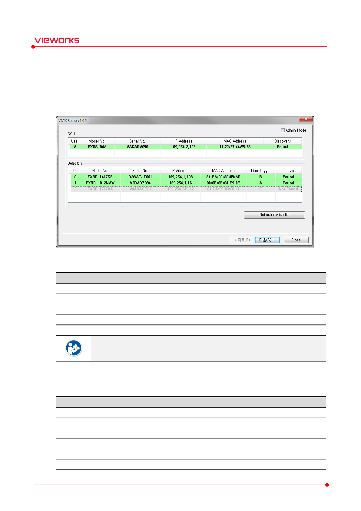
3.2 Checking Devices (Discovery Dialog)
How to Use
1 From the Discovery dialog box, check the list of detectors and SCU which are able to be connected with
the network.
2 Choose the detector and SCU to be accessed to the device, and then click Next button.
VIVIX Setup Operation Manual
3.2.1 Status Information
hite background
Double click the device name or click Select / Release buttons to register the device or
not.
3.2.2 SCU
Indicates the list of SCU which is able to be connected or has been connected once.
.
egistered status. Allowed to get into the device.
-registered status. Not allowed to get into the device.
indicate whether to use SCU or not. ‘V’ is checked to
SCU.
SCU.
it is not connected now.
Rev.1.1.12 Page 28 of 114 VW40-15A-003
SCU.
SCU.
SCU is found or not. (Found / Not found)
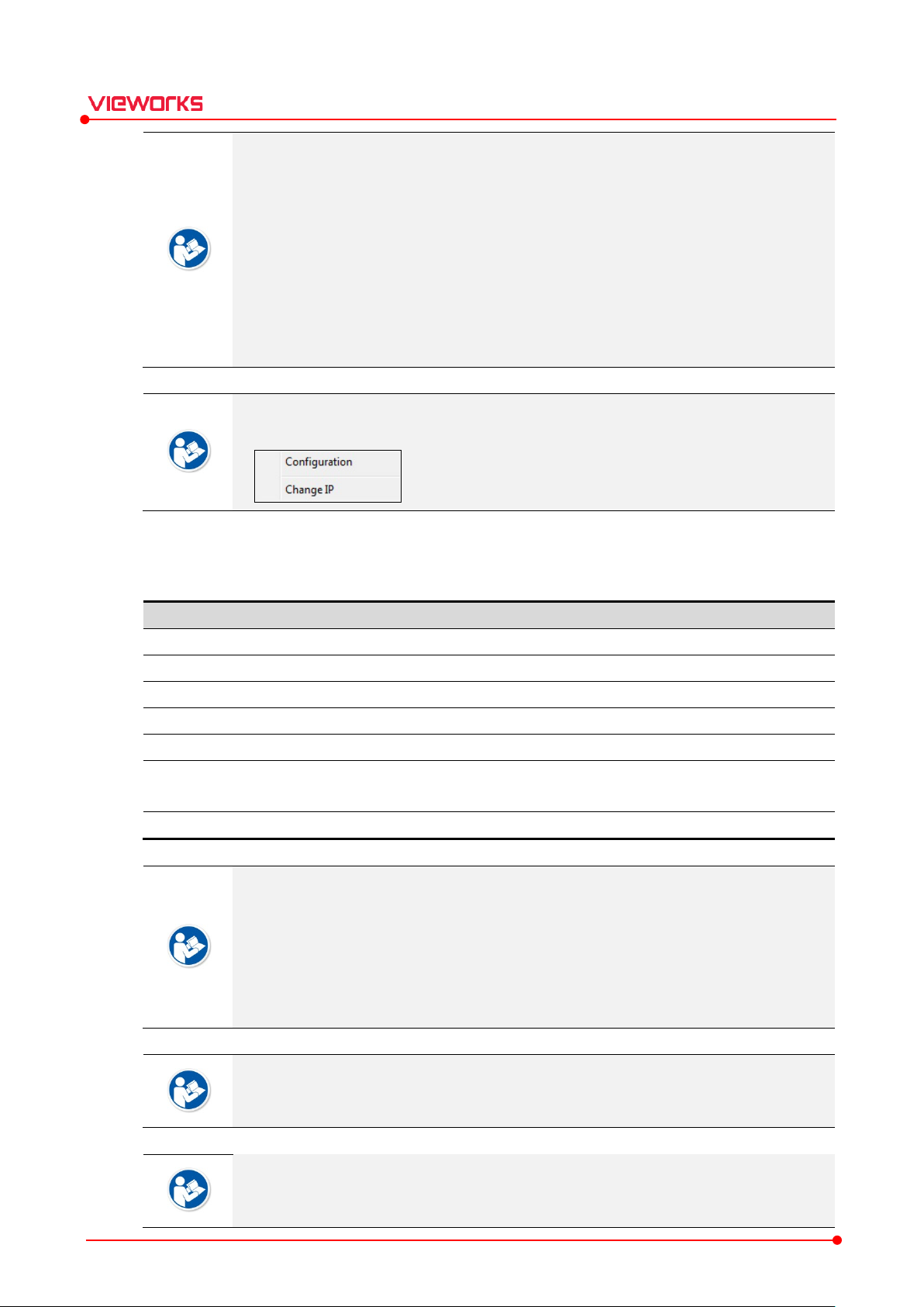
SCU model name and click on the right mouse button to change its information
Item Description
ID Indicates a sequence to
M
Indicates a model name of the
S
Indicates serial number of the detector and
I
Indicates IP address of the detector or
M
Indicates MAC address of the detector
Line Trigger
When setting Trigger Method of SCU to Line Trigger, select pin group to
connected with detector. Refer to <
Discover
Displays whether a detector is found. (Found / Not found)
VIVIX Setup Operation Manual
Set SCU from the Discovery dialog to transmit / receive images and the related
information through it.
The default address of SCU is 169.254.2.100.
Check if the SCU IP address is collided with another and change the IP address suitable
for the communication environment.
It is not allowed you to change MAC address, the unique identifier assigned to a network
device.
If the result of Discovery is Not found, it means that the SCU has been used once, but
cannot be found now.
Choose a
and IP address. Refer to SCU Configuration for the detailed information.
3.2.3 Detectors
Indicates the list of detectors that are able to be connected or have been connected.
odel No.
erial No.
P Address
AC Address
y
distinguish the registered detectors.
detector.
SCU.
SCU.
.
Up to five (5) detectors are indicated on the list.
3.4.4Trigger>.
be
Click ↑/↓buttons to change the order of detector ID on the list.
A detector ID is just the sequence to distinguish the registered detectors. It does not
mean the unique value of a detector.
The default ID address of a detector is 169.254.1.10.
Please do not change MAC address, the unique identifier assigned to a network device.
Line Trigger can be set in SCU Configuration. Refer to <3.4 SCU Configuration Dialog>.
Rev.1.1.12 Page 29 of 114 VW40-15A-003
Select the detectors to be connected directly to generator's hardware ports A, B, and C.
Choose a detector model name and click on the right mouse button to change its
information and IP address. Refer to Detector Configuration for the detailed information.
When connecting multiple detectors, you are encouraged to designate and manage the IP
VIVIX Setup Operation Manual
address in person.
If the multiple detectors with the same IP address simultaneously access to the network,
the detector that gets on the network later automatically finds other non-overlapping IP
address to prevent IP address conflict.
If more than 2 detectors, with the same IP, attempt to register without being connected
to the network, the IP Change window pops up. To register the detector, the change of
the IP address should be successfully made.
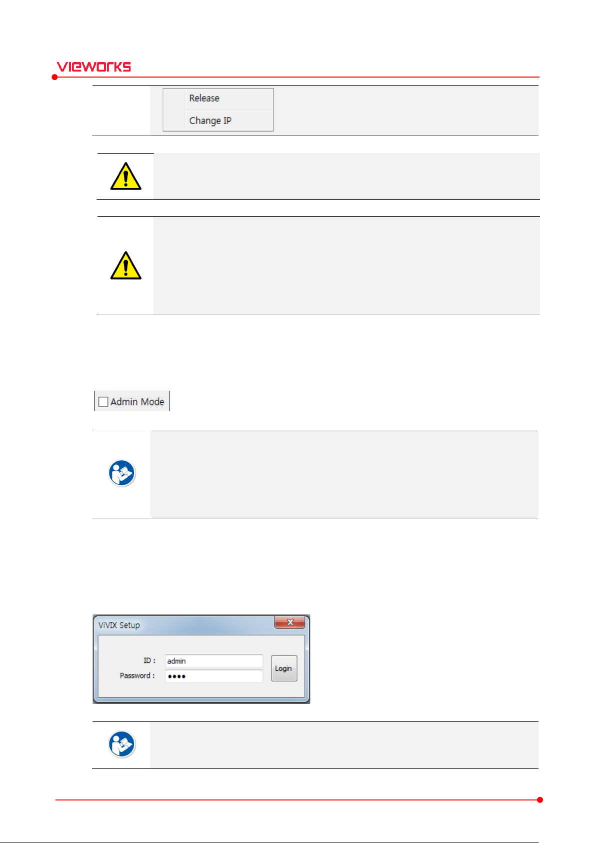
3.2.4 Admin Mode
Check Admin Mode to enter the administrator mode.
How to Enter Admin Mode
1 Check Admin Mode.
2 Click Next button.
3 Input administrator ID and password to enter the Admin mode.
You can check or configure the followings by entering the Admin mode.
You can change Country in the AP option from the Detector Configuration dialog.
You can check Capture Count/Total Shot Count from Image Dialog and Maintenance
Dialog.
You can check Acceleration Sensor Calibration UI from Calibration Dialog.
The default login ID is admin, and the password is 1234. You can change both ID and
password after logging on to VIVIX Setup.
Rev.1.1.12 Page 30 of 114 VW40-15A-003

Item Description
Refresh
Searches all
Back
Enters the dialog to discover detectors and SCU.
Next
Enters
Close
Closes the dialog being used.
3.2.5 Buttons
VIVIX Setup Operation Manual
Device List
Check the connection status of a detector or SCU if no device is indicated on the list
when clicking Refresh Device List button.
Check if the network speed is set correctly when you cannot enter the Main Dialog or it
takes a long time to enter the main dialog after clicking Next button.
SCU and detectors connected with the same network again.
the main dialog for the selected detector and SCU.
Rev.1.1.12 Page 31 of 114 VW40-15A-003

Name
Description
Configuration
Checks or changes the setting information of the detector or SCU.
Calibration
Checks or calibrates the calibration data of the detector.
Image
Checks and diagnoses
Maintenance
Checks the battery and wireless connection of the detector as well as diagnoses
its main functions.
Change ID & Password
Changes administrator ID and password when entering to the Admin mode.
3.3 Getting into the Device (Main Dialog)
How to Use
1 Check the connecting detector and SCU from the Main Dialog.
2 Click on the desired button to use a function.
VIVIX Setup Operation Manual
The number of buttons in the main dialog may display differently depending on which
detector and SCU models are connected.
3.3.1 Information Display
Display System
Device type : Model name (Serial number) [IP address] [MAC address]
Status : Connection status Configuration button Calibration button Image button Maintenance
button
Example
3.3.2 Buttons
Rev.1.1.12 Page 32 of 114 VW40-15A-003
images acquired from the detector.

3.4 SCU Configuration Dialog
How to Use
1 Check the information of SCU.
2 Change the information according to the purpose of use.
3 Click Set Config button to save the changed information.
VIVIX Setup Operation Manual
3.4.1 System
You can check the system information of SCU.
You can upgrade the components such as firmware, kernel, package, etc.
The screen image above is for connecting FXRS-03A (SCU) model. The screen may
display differently depending on which detector models is connected.
Rev.1.1.12 Page 33 of 114 VW40-15A-003

Item Description
Model
SCU model name
Serial No.
SCU serial numbers
FirmWare
Information of
BootLoader
Information of
Kernel
Information of
Package
Information of
Item Description
IP Address
IP address of
Net Mask
Subnet mask of
Gateway
Gateway of
VIVIX Setup Operation Manual
No.
The Firmware, BootLoader, and Kernel are unified as a form of package from the
recently released SCU.
SCU firmware version
SCU bootloader version
SCU kernel version
SCU package version
How to Upgrade Firmware or Package
1 Prepare the firmware or package file to upgrade.
2 Click Upgrade button and choose the prepared file.
3 Click OK button to upgrade the file.
Be sure to check the connection status of SCU before upgrading the file.
Be careful to prevent disconnects of communication with SCU while the file is being
upgraded.
If the file cannot be upgraded, try again. Contact the person in charge of service if this
problem continues on.
3.4.2 Network
You can check and configure the network information of SCU.
You cannot upgrade BootLoader directly.
Contact the person in charge of service if you need to upgrade Kernel since it has the
environmental information for operating the detector.
SCU
SCU
Rev.1.1.12 Page 34 of 114 VW40-15A-003
SCU

Item Description
AP On / Off
Activate or deactivate the
Country
The list of
Frequency
F
Band
W
Default frequency band.
Expands bandwidth through channel bonding.
Channel
W
SSID Service Set
Key Unique
Security
Authentication security
Uses
Uses
Gi Guard i
Tx Power(%)
Sets the power of radio frequency
The default address of SCU is 169.254.2.100.
Check if the SCU IP address is collided with another and change the address suitable for
the communication environment.
3.4.3 AP (Access Point)
You can check the AP (Access Point) information of SCU.
VIVIX Setup Operation Manual
20 ㎒
40 ㎒
countries using wireless network (80 countries)
requency channel of wireless network. (2.4 ㎓ / 5 ㎓)
ireless network bandwidth.
ireless communication channel
ID for wireless communication
key for wireless communication (Applied to the password only.)
SCU AP (Access Point) function.
WPA-PSK
WPA2-PSK
When you use SCU as an access point (AP), it means that the system is communicated
wirelessly under the SCU AP mode. Refer to VIVIX-S User Manual to understand features
of each mode.
Rev.1.1.12 Page 35 of 114 VW40-15A-003
for wireless communication
TKIP encryption algorithm. (Not support 802.11n)
AES encryption algorithm AES. (Supports 802.11n)
nterval of wireless communication
on the transmission side.

VIVIX Setup Operation Manual
You can set Country under the Admin Mode only.
The number of serviceable channels is different according to the configured country.
Before you set Country, make sure that the country has acquired Wi-Fi certification. Be
careful not to choose a country where Wi-Fi is not certified.
13 channels can be used in 2.4 ㎓ Frequency.
8 channels can be used in 5 ㎓ Frequency.
Channel bonding is used for enhancing transmission speed. However, the speed may be
slowed down due to the interference of surrounding channels, even if the channels have
been bonded.
Channel items (+/-) will be activated in case of using 40㎒ frequency bandwidth. You can
set whether to bond channels with the above or below one.
To connect a detector with SCU AP, refer to the SSID and Key values on the screen
image above.
SSID and Key values should not be duplicated with those of the peripheral system.
The maximum value of SSID is 20 letters and the Key is 63 letters. (Minimum Key value is
8 letters). The input letters are limited to capital / small alphabets, “-“, “_” among special
letters and numeric characters.
Use WPA2-PSK, which has more intensified encryption algorithm than WPA-PSK.
802.11n provides 400ns option for the guard interval between the transmission symbols
exist in the standard of wireless specifications.
Wireless network setting should be done by an engineer who understands the wireless
communication and its related technique. Unless the network is set properly, a
communication error would occur or the image quality would be affected.
Rev.1.1.12 Page 36 of 114 VW40-15A-003

Item Description
Method
Trigger
Software t
Hardware t
Polarity
Polarity of trigger signals
Recognizes
Handles polarity of A
H
3.4.4 Trigger
You can set the trigger information for integrating SCU with X-ray generator.
VIVIX Setup Operation Manual
Packet
Line
AUTO (Default)
HIGH
LOW
The setting value of Trigger is applied only when the exposure mode is set as the DR
Trigger mode. The value cannot be applied if the exposure mode is set as the AED
mode.
Packet trigger
method
rigger method
rigger method
polarity of trigger automatically and handles it.
ctive High
andles polarity of Active Low
Rev.1.1.12 Page 37 of 114 VW40-15A-003
N detectors share one generator signal.
SCU receives the generator signal, creates packet by S/W, and sends the signal to the
detectors.
When you connect the generator, connect a generator interface cable to only one pin
group.
It sends and receives a selected detector and generator signal through the
SelectDetector function of SDK for shooting images.

Item Description
On / Off
Selects whether the transmission function
Period
T
VIVIX Setup Operation Manual
Line trigger
N detectors are connected to N generators individually to share signals.
Up to three generators can be connected.
Directly connects the generator with the port assigned to the Setup program.
Refer to <3.2.3 Detectors> for how to connect each generator signal to the detector.
3.4.5 Test Mo de
You can check the interface state for acquiring images between the detector / SCU and X-ray generator.
It is possible to send trigger signals to the detector every certain period of time.
Refer to VIVIX-S Service Manual for more information about trigger settings.
of trigger signal is used or not.
ime interval for transmitting trigger signals. (Unit: second)
Test Mode is used for testing validity of the interface signal of X-ray generator
Rev.1.1.12 Page 38 of 114 VW40-15A-003

Item Description
Set
T
Factory Reset
Initializes
Log Checks
C
Closes the
setting value will not
The Trigger and Test Mode settings should be done by an engineer who fully
understands the X-ray generator. Unless the detector and X-ray generator are set
properly, an integration error could occur, or the system operation could be affected.
3.4.6 Order Buttons
VIVIX Setup Operation Manual
Config
ancel
ransmits current setting values to SCU for an update.
SCU to its factory default settings.
and downloads the log information of SCU.
SCU Configuration dialog. If Set Config is not performed, the changed
be applied to SCU.
Refer to VIVIX-S User Manual for the information about factory default settings.
How to Download the SCU Log File
1 Click Log button.
2 Set the range of dates for generating log files and click Search button.
3 Choose a log file from Log List and click Download button to save the file to the PC.
Rev.1.1.12 Page 39 of 114 VW40-15A-003

3.5 Detector Configuration Dialog
How to Use
1 Check the detector information.
2 Change the information according to the purpose of use.
3 Click the Set Config button to save the changed information.
VIVIX Setup Operation Manual
The screen image above is the Detector Configuration dialog of FXRD-3643VW
detector. The screen may display differently depending on which detector model is
connected.
Refer to <6 Appendix> for the information about the items that vary from the screen
depending on each detector model.
When the value stored in the detector and the value displayed in UI are changed, it turns
red like the above screen image, which means that the item has been modified.
Rev.1.1.12 Page 40 of 114 VW40-15A-003

Item Description
IP Address
IP address of the detector
Subnet
Subnet Mask of the detector
Gateway
Gateway of the detector
Item Description
SSID The SSID value of AP where the detector is
Key The key value of AP where the detector is
Wireless Only
The detector is communicated wirelessly whether a
connected or not
Wireless Only
The detector is communicated through wired connection when a tether interface
cable is connected.
The detecto
AP
Scans AP around the detector (for FXRD
3.5.1 Network
You can check and set the network information of the detector.
VIVIX Setup Operation Manual
Mask
3.5.2 WNetwork
You can set the AP (Access Point) information to communicate with the detector wirelessly.
The default address of the detector is 169.254.1.10.
Check if the detector IP address is collided with another and change the IP address suited
to the communication environment.
On
Off
Scan
.
r is communicated wirelessly if a tether interface cable is not connected.
Set WNetwork in case the detector is used as STATION for wireless communication.
Input SSID and Key of SCU in case you use SCU AP for wireless communication.
Rev.1.1.12 Page 41 of 114 VW40-15A-003
going to be connected wirelessly.
going to be connected wirelessly.
tether interface cable is
-1417W only.)

Item Description
A
Determines w
Enable
Enables or disables the Detector AP (Access Point) function.
Country
The list of countries where using wireless network. (80 countries)
Frequency
Radio frequency
Band
W
How to Synchronize Wireless Setting between Detector and SCU
You can synchronize the wireless setting by connecting a detector and SCU with a tether interface cable to
use SCU as AP, and to use detector as STATION.
1 Connect the detector and SCU with a tether interface cable.
2 Press the detector AP button for 5 seconds after the detector is turned on.
3 AP LED of the detector blinks in orange while processing synchronization.
4 The SSID and KEY information of SCU is configured as those of WNetwork automatically.
5 The detector is switched to the STATION mode for wireless communication.
This function supports the N-type detector models only.
3.5.3 AP (Access Point)
VIVIX Setup Operation Manual
You can check and configure the AP (Access Point) information.
<AP items of FXRD-1417W> <AP items of FXRD-3643VW>
P Button Type
Rev.1.1.12 Page 42 of 114 VW40-15A-003
ireless network bandwidth.
hich action to take when the AP button is pressed. (for VW series only)
(2.4 ㎓ / 5 ㎓)

Default frequency band.
Expands bandwidth through channel bonding.
Expands bandwidth
Channel
W
SSID Unique
Key Unique
Security
Authentication security
Uses
Uses
Gi Guard interval
Tx Power(%)
Sets
for
VIVIX Setup Operation Manual
20 ㎒
40 ㎒
80 ㎒
WPA-PSK
WPA2-PSK
When you use the detector as an access point (AP), it means that the system is
communicated wirelessly under the Detector AP mode. Refer to VIVIX-S User Manual
the detailed information about each mode.
You can set the country under the Admin Mode only.
The number of serviceable channels is different according to the configured country.
ireless communication channel
ID for wireless communication
key for wireless communication (Applied to the password only)
TKIP encryption algorithm. (Not support 802.11n)
AES encryption algorithm AES. (Supports 802.11n)
of wireless communication (for FXRD-1417W only)
power of radio frequency on the transmission side. (for FXRD-1417W only)
through channel bonding.
for wireless communication (for FXRD-1417W only)
13 channels can be used in 2.4 ㎓ Frequency (8 channels in 5 ㎓ Frequency).
Channel bonding is used for enhancing transmission speed. However, the speed may be
slowed down due to the interference of surrounding channels, even if the channels have
been bonded.
Channel items (+/-) will be activated in case of using 40㎒ frequency bandwidth. You can
set whether to bond channels with the above or the below one.
Refer to SSID and Key values indicated on the screen image above to connect
workstation with detector AP.
SSID and Key values should not be duplicated with those of the peripheral system.
The maximum value of SSID is 20 letters and the Key is 63 letters. (Minimum Key value is
8 letters). The input letters are limited to capital / small alphabets, “-“, “_” among special
letters and numeric characters.
Use WPA2-PSK, which has more intensified encryption algorithm than WPA-PSK.
802.11n provides 400ns option for the guard interval between the transmission symbols
exist in the standard of wireless specifications.
Rev.1.1.12 Page 43 of 114 VW40-15A-003

Item Description
Sleep
If the detector is not used for the specific setting time, it
(
Shut Down
If the detector is not used f
(
Power Control
Sets standards of power supply to the detector.
The
I
The detector is operated by SCU
the SCU
Sets the function to turn on the detector immediately when the tether interface
cable is connected
Sets the function to turn
cable is connected
P
Set
VIVIX Setup Operation Manual
Wireless network setting should be done by an engineer who understands the wireless
communication and its related technique. Unless the network is set properly, a
communication error would occur, or the image quality would be affected.
Switching to the Detector AP Mode with the Detector AP Button
You can switch the setting mode to the detector AP mode by using the detector AP button.
1 Press the AP button on the detector for 5 seconds.
2 The AP LED blinks in a blue color while the mode is being switched.
3 The AP LED turns on a blue color after the mode is switched.
The detector AP button supports N-type detectors only.
The VW series detector switches to AP mode when the AP Button Type is “AP / Station”.
The detector AP button can be used under the wireless communication only, without
connecting the tether interface cable to the detector.
3.5.4 Power Mode (Power Management)
You can manage the detector power and set the relevant information.
by Detector
10 / 15 / 20 / 25 / 30 min.)
10 / 15 / 20 / 25 / 30 min.)
detector operates by all power supply such as SCU power and battery.
f the SCU power and battery is blocked, the detector is turned off.
turns to the sleep mode.
or the specific setting time, it is turned off.
by SCU
Auto Power On
Auto Power Off
erformance Option
Rev.1.1.12 Page 44 of 114 VW40-15A-003
power is blocked, the detector is turned off.
.
off the detector immediately when the tether interface
.
s the detector to performance priority / battery saving mode. (VW detector only)
power with connecting a tether interface cable. If

Item Description
Normal
The detector can be operated and take image
Sleep
The detector cannot be operated.
Shut Down
The detector has been turned off.
Item Description
Normal
-
Sleep
The detector
(Sleep after).
Shut Down
The detector is turned off if not used for the
sleep mode. However, if the detector is not used during the setting time (Shutdown
after) under the sleep off state, the detector is turned off.
VIVIX Setup Operation Manual
Supported options may differ depending on the detector model.
You can prevent unnecessary battery consumption by using the Sleep function.
The Sleep mode and Shutdown function are activated only when the detector is
operated by a battery pack. Therefore, they are inactivated when SCU supplies power to
the detector by connecting a tether interface cable.
When you use the Sleep function, be sure to check if the detector is under Sleep mode
before shooting X-rays. The detector cannot acquire images under Sleep mode.
It takes up to fifteen seconds to wake up the detector from Sleep mode. The images
cannot be acquired during this time.
If Power Control is set to by Detector and the tether interface cable is disconnected, you
can keep using the detector by battery power. In this case, press the power button for 3
seconds to turn off the detector.
If a tether interface cable is disconnected while Power Control is set to by SCU, the
detector is turned off since the battery cannot supply power to the detector.
Wireless network setting should be done by an engineer who understands the wireless
communication and its related technique. Unless the network is set properly, a
communication error would occur, or the image quality would be affected.
Power Mode Type
Condition to Enter Sleep Mode
s at any time.
Disable the Sleep mode to take images.
Reboot the detector to take images.
Rev.1.1.12 Page 45 of 114 VW40-15A-003
enters sleep mode if the image is not taken during the setting time
setting time (Shutdown after) under the

Item Description
Normal
All LED lamps are turned on.
Sleep
Shut Down
All LED lamps are turned off.
Item Description
Normal
-
Disabling
1
2
3
Shut Down
Reboot the detector by pressing a power button on the detector
Mode
Default value
Turnaround time
Power consumption
Normal
- -
24V, 300mA (Standby)
24 V, 600mA (While taking images)
Sleep
OFF / 10min.
Approx. 10 sec.
24V, Max. 150mA
Shut Down
OFF / 30min.
Approx.
-
VIVIX Setup Operation Manual
Checking Displays of Sleep Mode
Power LED (Green) is blinking.
You can check the sleep mode from VIVIX Setup or VXvue.
VIVIX SDK indicates the state of sleep mode.
Disabling Sleep Mode
Sleep
Other Information
Press the power button of detector to disable the sleep mode.
Turn off the sleep mode from VIVIX Setup or VXvue.
Call the function from VIVIX SDK to turn off sleep mode.
.
15 sec.
Rev.1.1.12 Page 46 of 114 VW40-15A-003

Trigger Type
Description
DR
The X
ray
shooting signal of the gene
using SCU provided by Vieworks
with the generator. The generator sends a photographing request signal EXP_REQ to
the detector, generates an X
EXP_OK from the detector, and the detector acqui
Passive Trigger
D
the detector with a generator interface cable
the generator shoots X
to the detector.
AED
Detects X
The detector acquires images after the automatic detection
.
3.5.5 Exposure Mode
You can set the exposure mode with X-ray generator to acquire images.
VIVIX Setup Operation Manual
Trigger
etects the X-ray exposure signal of X-ray generator in advance by connecting it to
-ray generator and the detector are connected to each other to receive the X-
rator and let the detector acquire images. The developer
or using VIVIX SDK can directly link the two devices
-ray after confirming the photographing ready signal
res the image.
. To make the detector acquire images,
-ray right after it sends the exposure request signal (EXP_REQ)
-ray automatically without connecting the detector with X-ray generator.
.
To use DR trigger or passive trigger by connecting X-ray generator and detector through
SCU, you must connect between X-ray generator and SCU by a generator interface cable.
In the case of a detector using drive mode, you can check the corresponding item in the
System configuration menu of the Calibration dialog box.
3.5.6 Auto Offset Refresh Setting
Setting to refresh the offset calibration data automatically.
You can perform an offset update by applying the Use offset refresh option as follows.
Rev.1.1.12 Page 47 of 114 VW40-15A-003
In every setting time of Time Interval, this option checks the detector temperature
difference between the current one and the other at the time of previous offset update

Item Description
Time
Time limit for
O
Choose one of the options
Preview
If the temperature difference is larger than that of setting at Temperature Interval, the
offset update is performed as many times as setting in Number of shot.
If you use VXvue, a pop-up message will be displayed before offset update, and click OK
button to perform automatic offset update.
For detector models that do not require offset calibration, the Auto Offset Refresh setting
is also not used.
3.5.7 Image (Image Timeout)
You can check and set the time limit of image transmission.
Set whether you use the preview function or not when you send images.
VIVIX Setup Operation Manual
ption
out (sec.)
completing the image transmission
to send a preview image or to use FTM. (None /
/ FTM)
For FXRD-N type model only.
After starting image transmission, the detector ignores the information of image re-
transmission request if the following conditions are fulfilled.
The time limit of image transmission does not exceed.
The images are not transmitted completely.
The Preview function can be used under wireless connection only.
With using the Preview function, the preview image is transmitted first. This makes you
feel checking the image faster although the total transmission time gets longer.
Preview image is a 4x4 binning one, 1/16 size of the original image.
The transmission speed of a preview image is 2 seconds for the FXRD-1417W detector.
The transmission speed of a preview image is 1 second for the N-type detector.
Rev.1.1.12 Page 48 of 114 VW40-15A-003
Fast Tact-time Mode supports FXRD-1012N / VXDT-2532E detectors only. This mode
can be used under the wireless communication status.
In case of using Fast Tact-Time Mode, the preview image is transmitted only, while the
original one is saved to the detector separately.

Item D
Auto
Uses the direction information set in the detector
Off Uses the direction information set in the Setup program
Item Description
On Increases
Off Sends the data packet in regulated
Item Description
Load
Opens the window to
Setting
Op
Set Config
Transfers the current setting value to the detector and updates it
C
Closes the window
3.5.8 User Input Direction
Choose whether to use the direction information set in the detector or the direction information set in the
Setup program.
This feature only supports the FXRD-1417N detector only.
escription
VIVIX Setup Operation Manual
3.5.9 Inter Packet Delay
You can set time interval when transmitting the data packet from the detector.
The Inter Packet Delay function supports FXRD-1717S, FXRD-1417S and FXRD-1717V
detectors only.
.
.
transmission time interval between the data packets.
speed.
3.5.10 Buttons
lose
Rev.1.1.12 Page 49 of 114 VW40-15A-003
ens the preset setting window.
read the list of currently stored presets.
.
without sending the modified setting value to the detector.

VIVIX Setup Operation Manual
How to load the preset data
You can load and use the preset data stored in the detector.
1 Click the Preset Load button.
2 Click the drop-down control to view the list of saved presets and select the name of the preset you want
to recall.
3 Click the OK button.
4 The content of the Configuration window changes to the one stored in the Preset. Items are not applied
until you click Set Config.
The detector that supports preset function has an OLED.
Rev.1.1.12 Page 50 of 114 VW40-15A-003

3.6 Preset Configuration
Preset is a function that saves configured values in the detector and instantly changes them to saved
preset. Only detectors with the NFC function or detectors with the AP switching button can use this
function.
How to Use
1 Check the contents of the preset data stored in the detector.
2 Add or delete preset data according to the purpose of use.
3 Set the card select value linked with each color of NFC card. Do not enter if the detector does not
support NFC.
4 Click the Save button to save the changed information.
VIVIX Setup Operation Manual
3.6.1 Setting the Preset List
You can add or delete the preset items.
1 Click the Add preset button to add new preset items.
2 Click the Del preset button to delete preset items.
The Import and Export functions will be implemented in the future.
3 If you select a preset name in the list, the contents of the selected preset are
displayed on the screen.
Rev.1.1.12 Page 51 of 114 VW40-15A-003

3.6.2 Setting the Individual Preset Item
VIVIX Setup Operation Manual
How to set preset
1 The basic preset items are same as those of Configuration.
2 Change the preset name and click the Set Name button to renew the name of list.
3 Choose the option of Card Select to determine which color is linked with the current NFC card.
4 Adding / deleting preset data by pressing the Add Preset or Del Preset button cannot correct the
information inside the detector. Click the Save button to save the changes.
Only the color is saved on the NFC card without the setting value.
The preset name must be a different value for each preset item.
After modifying the preset, it is recommended to use the Preset Load function manually
for synchronization with Config.
Rev.1.1.12 Page 52 of 114 VW40-15A-003

VIVIX Setup Operation Manual
4. Calibration
This chapter gives information about the functions and methods of calibration.
Calibration Guide
Calibration Dialog
System Configuration
Drive Mode
Offset Calibration
Defect Calibration
Gain Calibration
Acceleration Sensor Calibration
Detector Configuration
Rev.1.1.12 Page 53 of 114 VW40-15A-003

4.1 Calibration Guide
The different installation environment of each detector and unique features of the X-ray generator device
can affect the acquired images. Therefore, the service engineer should do the detector calibration after
installing a detector newly or changing system. Otherwise, the image quality can be affected seriously.
Vieworks provides two types of calibration method.
Performing calibration by loading the calibration data provided by Vieworks.
The service engineer performs calibration and generates calibration data.
We strongly recommend the service engineer to perform the calibration in person since
the detector condition and image quality can be different by the operation method or
use environment.
VIVIX Setup Operation Manual
Rev.1.1.12 Page 54 of 114 VW40-15A-003

4.2 Calibration Dialog
You can configure and calibrate the detector suitable for the shooting environment to acquire normal
images.
VIVIX Setup Operation Manual
4.2.1 How to Use
1 Click the Calibration button in the main dialog to move to the Calibration dialog.
2 Choose the System Configuration menu to set the generator interface information.
3 Choose the Offset Calibration menu to calibrate Offset data.
4 Choose the Gain Calibration menu to calibrate Gain data.
5 Choose the Defect Calibration menu to calibrate Defect data
6 Choose the Defect Configuration menu to check the image before/after the calibration, and set the
detector.
It is recommended to perform Offset and Gain calibration first, and then perform Defect
calibration with the image applied the renewed Offset and Gain data.
The field engineer should choose the menus that are most suited to the exposure
environment for setting and calibrating the detector.
Rev.1.1.12 Page 55 of 114 VW40-15A-003

Menu
Description
System Configuration
Configures the exposure
Offset Calibration
Calibrates Offset
Defect Calibration
Calibrates Defect data of the detector.
Gain Calibration
Calibrates image sensitivity of the detector.
A
C
Detector Configuration
Configures the detector information related to calibration and image
4.2.2 Menu
VIVIX Setup Operation Manual
cceleration Sensor
You can calibrate the sensor making it parallel to the table used for installation.
It is not recommended to re-calibrate the acceleration sensor except when utilizing pitch
alibrates acceleration sensor of the detector
The status is displayed as Done when each calibration is completed from Offset, Defect,
and Gain Calibration menus. You cannot operate the detector if the status is not
displayed as Done.
You can execute the acceleration sensor calibration in the admin mode.
and roll data of the acceleration sensor.
data of the detector.
time and Gain type.
s.
Rev.1.1.12 Page 56 of 114 VW40-15A-003

Item Default
Description
Exposure Time
50
The t
EXP OK Delay Time
1
The delayed time to receive EXP_OK signal from the detector after the
generator sent EXP_REQ signal to the detector
Debounce_DR
3
The required time to
image
Trigger is selected only
Debounce_AED
3
The required time to check sensor signal from X-ray to prevent image
acquisition
only
4.3 System Configuration
From the System Configuration menus, you can set the detector exposure mode and the generator
interface information.
VIVIX Setup Operation Manual
Be sure to click SET button at the right after changing each parameter in System
Configuration. The modified setting cannot be applied without clicking this button.
4.3.1 Exposure Timing
You can set the timing information necessary for accurate image acquisition.
Each timing information may vary depending on the X-ray generator characteristics.
Rev.1.1.12 Page 57 of 114 VW40-15A-003
㎳
㎳
㎳
0㎳
ime to acquire X-ray by the detector.
acquisition from external noise. It can be used when DR
.
.
check signals from the generator for preventing
.
from external noise. It can be used when AED is selected

VIVIX Setup Operation Manual
Exposure Timing Diagram
Exposure Time should be set longer than the maximum exposure time to prevent X-ray
loss.
The maximum Exposure Time is 10000㎳.
When Exposure Time is changed, be sure to generate new calibration data by calibrating
Offset and Gain data to get optimized images.
EXP OK Delay Time is the delayed time between the detection time of exposure request
signal (EXP_REQ) from the X-ray generator and the time before sending exposure
respond signal (EXP_OK) to the X-ray generator. Some X-ray generators need time to
prepare detecting EXP_OK signal after sending EXP_REQ signal. This time is determined
according to the specifications of X-ray generator.
Debounce_DR is used for removing the trigger signal due to external noise when the
exposure mode is set as DR Trigger. If the value is set to less than 3㎳, the detector may
acquire undesirable images.
Debounce_AED is used for removing trigger signals due to external noise when the
exposure mode is set as AED. If the Debounce_AED value is set longer than the X-ray
exposure time, the detector cannot acquire images. If unwanted images are acquired
without X-ray exposure while the equipment is operated, set Debounce_AED with 1㎳
increments. However, we recommend you not to set the value more than 10㎳.
Rev.1.1.12 Page 58 of 114 VW40-15A-003

4.3.2 Digital Offset
After Offset Calibration, you can configure base level of pixel on Digital Offset item in order to minimize
loss of pixel value if it is below base level point.
After changing Digital Offset, you do not have to execute new calibration.
4.3.3 Gain Type
You can control the detector sensitivity by selecting Gain Type to obtain desired X-ray images in
accordance with the specifications of X-ray generator or subject types.
VIVIX Setup Operation Manual
When Gain Type is changed, be sure to generate new calibration data by calibrating
Offset and Gain data to get optimized images.
In the case of a detector that uses drive mode, check the gain type setting item in the
drive mode setting box.
For accurate detector sensitivity information, contact the support department in Vieworks
Co., Ltd.
Rev.1.1.12 Page 59 of 114 VW40-15A-003

M
F
VIVIX
v
VIVIX
v
4.3.4 Smart W
Smart W is a function that automatically re-configures Exposure Time in accordance with the exposure
time of X-ray. It prevents loss even if Exposure Time is set shorter than the exposure time of X-ray.
Therefore, the value of Exposure Time set to the maximum value of X-ray exposure is reduced to the
minimum value, resulting in image transmitting speed improvement. The below UI is displayed when
connected to the detector supporting this function.
VIVIX Setup Operation Manual
Debounce Off AED Time is the minimum detecting time needed for AED Sensor, which
executes the Smart W feature, to confirm that X-ray exposure is over. Default value is
5ms. If abnormal image is acquired through being irradiated longer than the Exposure
Time, increase the value by 1ms.
Detector models and firmware versions that can use the Smart W function
odel
-S VW Series
-S FW Series
irmware ver.
1.0.7.0
1.0.0.0
Rev.1.1.12 Page 60 of 114 VW40-15A-003

4.4 Drive Mode
In the case of a detector that uses Drive mode, you can adjust settings related to Drive mode at the
bottom of the System configuration menu.
Drive mode is a function that saves shooting-related settings and saves them for each mode so that they
can be changed at once.
VIVIX Setup Operation Manual
Rev.1.1.12 Page 61 of 114 VW40-15A-003

4.4.1 Drive Mode List
VIVIX Setup Operation Manual
You can select a drive mode and change the setting value of the drive mode.
If you double-click a drive mode in the list, you can change the detector setting to the drive mode.
The set drive mode is shaded in green.
You can add or remove drive modes to the list by clicking Add or Remove button. When selecting a
drive mode to delete, click the drive mode once in the list.
The entire drive mode setting can be saved as a file by clicking the Download button. Click the Upload
button to apply all drive mode settings saved in file format to the detector.
Drive mode ‘0’ can be used as a single shooting mode, and the others can be used as a drive mode for
multi shooting.
After upload, drive mode ‘0’ is automatically selected.
Rev.1.1.12 Page 62 of 114 VW40-15A-003

4.4.2 Drive Mode Setting
VIVIX Setup Operation Manual
Name: You can set the name of the drive mode.
Trigger Mode: You can set the exposure mode. It is the same as the Exposure mode item in the
Configuration window.
Gain Type: Set the gain type. It is the same as the gain type item at the top of the System Configuration
menu.
Exposure Time: Set the time the detector acquires X-rays. In multi-frame mode, the value is set
automatically and cannot be modified.
Drive mode Gain: Adjusts sensitivity of pixel on the present Drive mode.
Acquisition Mode: You can set the X-ray acquisition method.
Radio: Takes 1 X-ray image.
Pulse Fluoro: Multi-frame images are taken at regular intervals according to the trigger of the
generator.
Continuous Fluoro: Multi-frame images are taken at regular intervals without syncing with the
generator.
Binning Mode: Collect images by binning.
None-binning mode: Does not use binning mode.
Binning 1.5x1.5: The image is acquired by binning a 3x3 pixel area of the image into a 2x2 pixel area.
Binning 2x2: The image is acquired by binning the 2x2 area of the image to 1 pixel.
Image Size: Displays the size of the binning image.
AOI Size: Sets the area to be transmitted in the binning image. When changing the binning mode, it is
automatically changed to the maximum value.
Rev.1.1.12 Page 63 of 114 VW40-15A-003

Save the settings with button at the bottom.
4.4.3 Fluoroscopy Setting
If you set Acquisition mode to Pulse Fluoro or Continuous Fluoro, fluoroscopy items can be set.
VIVIX Setup Operation Manual
Max Frame Rate: Displays the maximum frame rate. If you change Binning or AOI, it will change
automatically.
Frame Rate: Set the number of frames to collect per second. It cannot be set to a value greater than the
Max frame rate. If the value becomes larger than the Max frame rate by changing the binning or AOI,
the value is automatically changed to the Max frame rate.
Max Frame Count: Displays the maximum number of frames that can be collected in one shot. If you
change the binning or AOI, it will change automatically.
Frame Count: Set the number of frames to collect. If the value becomes larger than the Max frame count
by changing the binning or AOI, the value is automatically changed to the Max frame count.
Skip Frame Count: Set the number of frames to discard without transmitting. If you set this value, the
detector discards the image as much as skip frame count and then transmits the image as much as
frame count when shooting.
Click button at the bottom to save the settings.
Rev.1.1.12 Page 64 of 114 VW40-15A-003

Item Description
Current value
Shows
S
Select
calibration stage
Run Offset Calibration
Calibrates the Offset data.
Load Offset
L
Upload Offset
Upl
Download Offset
Downloads
O
Shows the path of the Offset calibration
Copy to
Shows the copied path of the
4.5 Offset Calibration
From Offset Calibration, you can calibrate or load the Offset data file.
VIVIX Setup Operation Manual
The screen image above is an example when the program is connected with the FXRD-
1417W detector. The screen may display differently depending on which detector model
is connected.
4.5.1 Offset Calibration Functions
tage
ffset Path
oads the information of selected Offset data file to the local PC memory.
oads the information of selected Offset data file to the detector.
image pixel value when calibrating the Offset data.
s the number of performing Offset calibration and shows each
.
the Offset calibration data in the detector to the local PC.
data in current use.
Offset calibration data.
If the detector serial number is indicated only in Offset Path without any folder path or
Some detector models work without offset calibration. In this case, the message 'This
Rev.1.1.12 Page 65 of 114 VW40-15A-003
You should load the Offset data if there is no information in Offset Path.
file name, it means that the offset data is stored in the detector.
model does not require offset calibration' is displayed.

4.5.2 Calibrating by Loading Offset Data
1 Copy the Offset calibration data in the CD provided by Vieworks to the PC. You can also copy the Offset
calibration data that has been generated directly.
2 Click Load Offset or Upload Offset button in the Offset Calibration menu.
3 Choose the Offset calibration data and load it.
4 Check if Status of the Offset Calibration menu is indicated as Done.
Since Offset calibration data is embedded in the N-type detector, It is not necessary to
upload the data separately.
Be sure to choose the Offset calibration data generated from the relevant detector. An
error message will show if you choose a wrong file or the file generated from other
detectors.
VIVIX Setup Operation Manual
Vieworks provides the offset calibration data as a CD or as embedding it in the detector.
However, we recommend you to calibrate the Offset data directly, as the detector
condition can be changed depending on the operating method or use environment.
4.5.3 Calibrating by Generating Offset Data
Preheat the detector for at least 30 minutes before starting calibration. The result of
measurement can be incorrect if the detector is not preheated sufficiently.
1 Set the number of Stage as 10 from the Offset Calibration menu.
2 Click Run Offset Calibration button to calibrate the Offset data.
3 Save the created Offset calibration data to the local PC.
It is recommended to follow the generation rule of a file name for calibration data when
you save the Offset calibration data.
Generation Rule: [Serial number]-[Calibration data name]-[Year,Month,Day].DAT
Ex) V3DABF019-Offset-2012-08-27.DAT
Detectors other than FXRD-1417S, FXRD-1417W, and FXRD-1717S do not need to store
offset calibration data in the detector nor to save them as separate files, as offset data is
not required.
Rev.1.1.12 Page 66 of 114 VW40-15A-003

Item Description
Target
Shows the target value
Current Value
Shows
S
Select
stage.
Get Starts
Cancel
Cancels
Status
Shows the readiness status of detector to take images.
Load Gain
L
Upload Gain
Uploads
Download Gain
Downloads the Gain calibration
G
Shows whether the Gain calibration data exists in the detector or not.
Gain
Shows the
G
A
4.6 Gain Calibration
You can calibrate the Gain data or load the Gain calibration data file.
VIVIX Setup Operation Manual
The screen image above is for connecting the FXRD-1012N detector. The screen may
display differently depending on which detector model is connected.
Target value for FXRD-1717S / 1417S / 1417W detectors : 2000
Target value for other detectors: 8000
4.6.1 Gain Calibration Functions
Value
tage
oads information of Gain data file stored in the local PC to the PC memory.
of image pixel when calibrating Gain data.
the image pixel value after taking images when calibrating Gain data.
s the number of performing Gain calibration and shows each calibration
Gain calibration.
Gain calibration.
(Ready / Not ready)
selected information of the Gain data file to the detector.
ain in detector
Path
ain Compensation
pplies compensation after gain calibration due to saturation error.
Load the Gain data if no information exists in Gain Path.
path of the applied Gain calibration data.
If the detector serial number is indicated only in Gain Path without any folder path or file
name, it means that the Gain data is embedded in the detector.
Rev.1.1.12 Page 67 of 114 VW40-15A-003
data stored in the detector to the local PC.

e recommend you to calibrate the Gain data directly, as the detector condition
4.6.2 Calibrating by Loading Gain Data
In case the Gain data is provided as a CD (Except the N-type detector)
1 Copy the Gain calibration data file from a CD (provided by Vieworks) to the PC, or copy the Gain
calibration data that you generated to the PC.
2 Click Load Gain button in the Gain Calibration menu.
3 Choose the Gain calibration data to load it.
4 Check if the Status of the Gain Calibration menu is indicated as Done.
In case the Gain data is embedded in the detector
1 Click Download Gain button in the Gain Calibration menu.
2 Specify the storage path of local PC and download the Gain data in the detector.
3 Click Load Gain button in the Gain Calibration menu.
4 Choose the downloaded Gain calibration data file to load it.
5 Check if the Status of the Gain Calibration menu is indicated as Done.
VIVIX Setup Operation Manual
FXRD-1417S, FXRD-1717S, FXRD-1417W and FXRD-1717V provide gain data on CD.
The user must download the gain data stored on the CD to the local PC and reload it.
The FXRD-1012N, 1717N and VXTD-2532E detectors cannot calibrate the embedded
Gain data automatically. Therefore, it is required to download the Gain data to the local
PC and load it again.
Other detectors directly use the gain calibration data stored inside the detector,
eliminating the need for a separate download or load process.
Be sure to choose the Gain calibration data generated from the relevant detector. An
error message will show if you choose a wrong file or the file generated from other
detectors.
Vieworks provides the Gain calibration data as a CD or as embedding it in the detector.
However, w
can be changed depending on its operating method or use environment.
Rev.1.1.12 Page 68 of 114 VW40-15A-003

4.6.3 Calibrating by Generating Gain Data
The detector condition can be changed depending on its operating method or use environment. In this
case, you can generate the Gain data suited to each use environment.
To perform Gain calibration, be sure to precheck the condition of X-ray generator, tube
and console for preventing any problems with the shooting environment.
1 Preheat the detector for longer than 30 minutes.
2 Put the collimator on center of the detector and open it completely.
3 Adjust SID to 150cm or less to make X-ray exposure range include the detector.
VIVIX Setup Operation Manual
4 Remove any objects or foreign materials between the tube and the detector.
5 Set the tube voltage of X-ray generator as 70㎸ ~ 80㎸.
6 Choose the Gain Calibration menu.
7 If you are using a detector that uses 16-bit image (all detectors except FXRD-1417S, FXRD-1717S, and
FXRD-1417W), adjust the X-ray dose condition (㎃ or ㎳) until Current Value is formed between 8000 ~
10000.
8 If you run a detector using 14-bit image (FXRD-1417S, FXRD-1717S, and FXRD-1417W), adjust the X-ray
dose condition (㎃ or ㎳) until Current Value is formed between 1800~2200.
The grayscale of FXRD-1417S, FXRD-1717S, FXRD-1417W detectors is 14bit, and the
other detectors are 16bit, so the current value must be formed differently.
9 Set the number of exposure as 10 in Stage when the exposure condition is adjusted completely.
10 Click Get button, and shoot X-rays as many as the number set in Stage between 15 sec intervals.
11 When shooting is completed, a window for selecting the path to save the generated gain calibration
data will appear. Select a folder to save the Gain calibration data to a file.
Rev.1.1.12 Page 69 of 114 VW40-15A-003

VIVIX Setup Operation Manual
Make sure to calibrate the Gain data again for the following cases.
When the setting of Exposure Section is changed in the System Configuration menu.
When the setting of Gain Type is changed in the System Configuration menu.
When the exposure devices like X-ray generator are changed or repaired.
When the exposure environment is changed.
When the service engineer decides that it is necessary to perform Gain calibration.
We strongly recommend the service engineer to generate Gain data directly instead of
the Gain data provided by Vieworks since the detector condition can be different by the
operating method or by use environment.
When you generate the Gain data or load the existing one for the first time, the data file
for using OSF is created automatically with the file extension ‘sg’.
Detectors using drive mode can perform gain calibration only in radio mode.
4.6.4 Gain Compensation
This is a function that compensates for the difference between background pixels to which saturation is
applied and pixels to which saturation is not applied.
It is used when the background of the image is separated into two colors.
You can enter a range from 0 to 50%.
This function is only supported by certain detector models (VIVIX-S VW Series, FW Series).
The UI is not visible when connecting to other unsupported models or when the firmware
version is low.
Rev.1.1.12 Page 70 of 114 VW40-15A-003

4.6.5 Managing Partial Gain Data
When a detector that supports partial gain is connected, the partial gain table is displayed at the bottom of
the screen. The detector can be used by specifying a different gain for each partial mode.
Select the partial mode you want to create from the table and create gain data. The status of the partial
gain is displayed as Done.
When Gain Load/Download/Upload, all partial gains are managed as one integrated file.
VIVIX Setup Operation Manual
Partial Gain Storage
For detectors that support partial gain storage, a Partial Gain Storage button is displayed on the right side
of the partial gain table.
If you click the button, the partial gain related setting window appears.
For detectors that support partial gain storage, you can download gain data for each partial mode
separately.
1 Select the Partial mode you want to download from the Partial gain files menu.
2 Click the Download button and specify the download path of data.
3 When the download is complete, a download success message is displayed.
Rev.1.1.12 Page 71 of 114 VW40-15A-003

VIVIX Setup Operation Manual
Internal Storage
You can upload Partial Gain to the detector and load it directly into the detector.
Upload: Uploads partial gain file to internal storage.
Download: Downloads files uploaded to internal storage back to PC.
Remove: Deletes files uploaded to the internal storage.
Load: Allows the detector to use the gain file uploaded to the internal storage.
Rev.1.1.12 Page 72 of 114 VW40-15A-003

Item Description
Load Defect Map
Loads the Defect Map
Download Defect Map
Downl
Manual Defect Correction
Adds or modifies defects to the defect map through the
separately
Defect Map in
Shows whether the Defect Map data exists in the detector or not.
D
Shows path
L
Supports image processing
lower than the
recommended
4.7 Defect Calibration
You can load or calibrate the defect data file.
It is recommended to take images after renewing the Offset and Gain data by calibrating
both ones for defect calibration.
VIVIX Setup Operation Manual
The screen image above is an example when the program is connected with the FXRD-
1012N model. The screen image may display differently depending on which detector
model is connected.
4.7.1 Defect Calibration Functions
detector
efect Map Path
ower grid line support
Check Lower grid line support in case of using the grid which specification is lower than
the recommended one by Vieworks. If not, Grid Line Artifact can appear on the image.
Refer to VIVIX-S User Manual for the information about grid specifications
recommended by Vieworks.
data file to the local PC.
oads the Defect Map data in the detector to the local PC.
raw image taken
.
of the applied Defect Map data.
to the grid which specification is
one by Vieworks.
Rev.1.1.12 Page 73 of 114 VW40-15A-003

4.7.2 Calibrating by Loading the Defect Data
If Defect Map data is provided on a CD
1 Copy the Defect calibration data in the CD provided by Vieworks to the PC. You can also copy the Defect
calibration data that has been generated directly
2 Click Load Defect Map button from the Defect Calibration menu.
3 Choose the Defect calibration data file and load it.
4 Check if Status of the Defect Calibration menu is indicated as Done.
If Defect Map data is embedded in the detector
1 Click Download Defect Map button from the Defect Calibration menu.
2 Assign the storage path of local PC and download the Defect Map data stored in the detector.
3 Click Load Defect Map button from the Defect Calibration menu.
4 Choose the Defect calibration data file and load it.
5 Check if Status of the Defect Calibration menu is indicated as Done.
VIVIX Setup Operation Manual
FXRD-1417S, FXRD1717S, FXRD-1717V, and FXRD-1417W detectors provide Map
calibration data on CD. You must download the data to your local PC and then reload it.
The Defect Map data stored in the FXRD-1012N, FXRD-1717N and VXTD-2532E
detectors cannot be calibrated automatically. Therefore, it is required to download the
data to the local PC and upload it again.
Other detectors directly use the gain calibration data stored inside the detector,
eliminating the need for a separate download or load process.
Be sure to choose the Defect Map calibration data generated from the relevant detector.
An error message will show if you choose a wrong file or the file generated from other
detectors
Vieworks provides the Defect Map calibration data as a CD or as embedding it in the
detector This Defect Map data has been generated through stringent test in the
production stages of detector. However, new defect may be newly formed while using the
detector. In this case, make sure to calibrate defects directly and generate a new Defect
Map data.
Rev.1.1.12 Page 74 of 114 VW40-15A-003

VIVIX Setup Operation Manual
4.7.3 Calibrating by Generating Defect Data with Auto Defect Correction
Defect pixels can appear on the image while you use the detector. In this case, calibrate the defect pixels
with the auto defect correction function.
1. Preparation
Be sure to prepare the flat image with defect pixels before making auto defect correction.
1 Preheat the detector for longer than 30 minutes.
2 Put the collimator on center of the detector and open it completely.
3 Adjust SID to 150cm or less to make X-ray exposure range include the detector.
4 Remove any objects or foreign materials between the tube and the detector.
5 Check if the Status is indicated as Done by loading Offset, Defect Map and Gain calibration data.
Both the auto and manual defect calibration can be performed after registering Offset,
Defect Map and Gain calibration data.
2. Acquiring FLAT Image
1 In case of using the N-type detector, adjust X-ray dose to make the pixel value from 900 ~ 1100.
2 In case of using the detector except N-type one, adjust X-ray dose to make the pixel value from 400 ~
600.
You can check the pixel value from Image Dialog.
3 Move to the Image dialog and take FLAT images.
4 Click Save Image button and save raw images.
Rev.1.1.12 Page 75 of 114 VW40-15A-003

VIVIX Setup Operation Manual
3. Auto Correction
1 Move to Defect Calibration in the Calibration dialog.
2 Click Manual Defect Correction button and choose the stored raw images.
3 The Manual Defect Detection dialog displays.
4 Click Show and Apply buttons on the left top and then click Auto Defect Finder button.
5 Input 15% for Threshold, and 100 for Offset at the bottom of the Pixel List screen.
6 Click Search button at the bottom of the Pixel List screen. The coordinates of defect pixels and Gray
Level values display on Pixel list.
7 Press the Ctrl or Shift key and select the defect pixel items to be added to Defect Map.
Rev.1.1.12 Page 76 of 114 VW40-15A-003

VIVIX Setup Operation Manual
8 Click Add button to add the selected items to Pixel List in the Manual Defect Detection window.
9 Check if the selected defect pixels are added to Pixel List on the left
10 Click Save and Close button at the left bottom.
11 Save the newly generated Defect Map data to the path where the Calibration data has been stored.
It is recommended to save the new Defect Map data with a different name to preserve
the existing Defect Map data.
In case of using the detector except N-type ones, perform the defect correction once
again by getting an additional FLAT image with different conditions to secure better
image quality.
Ex.) In case of FXRD-1417S and 1717S models, get flat images which pixel values are
400 ~ 600 and 8000 ~ 10000 each. After that, perform auto defect correction again
with the two images. Then overwrite the Defect Map data file generated previously.
Detectors using drive mode can perform automatic defect correction only in Radio mode.
Rev.1.1.12 Page 77 of 114 VW40-15A-003

gray level
VIVIX Setup Operation Manual
4.7.4 Calibrating by Generating Defect Data with Manual Defect Correction
Execute manual defect correction when defect pixels are visible to the naked eye although the auto defect
correction has been performed.
The manual defect correction is divided into the pixel type and the line type.
Manual Correction – Pixel Type
1 Make sure to perform the auto defect correction from 1 to 11 steps first.
2 Click Show and Apply buttons on the left top of Manual Defect Detection.
3 Press and hold the right mouse button and move it to left/right/top/ bottom in the FLAT image to adjust
the brightness until you can verify the image with the naked eyes.
4 Click Add Pixel Button.
5 Use the Zoom or Pan function properly to find and click the location of defect pixel. A red point will
display, and coordinate of the pixel will be added on the Detect Map list on the left top.
6 Click Save and close button to save the Defect Map data with a new name.
If the brightness of selected pixels is different with the surrounding ones, or the
value is different with the adjacent pixels (more than 15%), the pixels are regarded as
defect pixels.
A window located on the left bottom magnifies and displays the pixel where the mouse
pointer is located. The coordinate and Gray Level value of the pixel displays under the
Rev.1.1.12 Page 78 of 114 VW40-15A-003
magnifying window.

gray level
even though you perform the manual defect
Detectors using drive mode separately manage defect information for each binning mode.
VIVIX Setup Operation Manual
Manual Correction – Line Type
1 Make sure to perform the auto defect correction from 1 to 11 steps first.
2 Click Show and Apply buttons on the left top of Manual Defect Detection.
3 Press and hold the right mouse button and move it to left/right/top/bottom in the FLAT image to adjust
the brightness until you can verify the image with the naked eyes.
4 Find and move to the start point of defect lines (line type) on the image.
5 Click Add V-Line or Add H-Line button.
6 Press and hold the left mouse button on the first defect pixel, move the mouse to the opposite direction
and release the mouse button on the last pixel of Line Defect pixel.
7 Select the Full Line checkbox and click the left mouse button to add the entire horizontal or vertical
Defect Line.
8 A red line displays on the image and check if pixels on the line are added to the Defect Pixel list.
9 Click Save and Close button to save the newly generated Defect Map data with a new name
If the brightness of selected pixels is different with the surrounding ones, or the
value is different with the adjacent pixels (more than 15%), the pixels are regarded as
defect pixels.
A window located on the left bottom magnifies and displays the pixel where the mouse
pointer is located. The coordinate and Gray Level value of the pixel displays under the
magnifying window.
If pixels without defect correction still remain
correction, contact the person in charge of service.
When using manual correction, you should upload an image suitable for the binning
mode and correct it, and the result of manual correction does not affect other binning
modes.
Rev.1.1.12 Page 79 of 114 VW40-15A-003

Function
Description
Show
Decides
Apply
Decides
Appl
Appl
Auto Defect Finder
Performs the auto defect correction.
Delete
Delete
Add Pixel
Add
Add V
Add
Add H
Add
F
When adding a
Delete Pixel
Deletes the defect pixel of a point on list of Defect Map.
Delete V
Deletes the defect pixel of vertical line on list of Defect Map.
Delete H
Deletes the defect pixel of
ROI Marks the area of interest.
Zoom
Zoom in or out the image
W/L Adjust
Pan Move
1:1 Displays the image as 1
Fit Displays the image as
Save
Saves the changed defect pixel information as Defect map data.
Close
Closes
VIVIX Setup Operation Manual
Functions of Manual Defect Correction
-Line
-Line
ull Line
All
Selected
-Line
-Line
whether the selected defect is indicated on the image
whether defects on the list are applied to the image.
ies all defects added to the list to the image.
ies selected defects from the list to the image only.
s the selected items from the list.
s one defect pixel to the Defect Map list.
s vertical line type of defect pixels to Defect Map list
s horizontal line type of defect pixels to Defect Map list.
line type defect, target the entire horizontal and vertical area.
horizontal line on list of Defect Map.
.
s the window level of the image to change the brightness.
and close
s the image to a desired location.
:1 ratio.
fitting it on the screen.
the window without saving the changed defect pixel information
Rev.1.1.12 Page 80 of 114 VW40-15A-003

I
D
x, y, z
Displays the read values of acceleration sensor for every 2 seconds.
Pitch
Gets rotation information of the detector by calculating the value of
and
z. The unit is degree.
s
D
D
c
If the model has the six
step displays.
If you re
Calibration is shown.
I
displayed.
I
4.8 Acceleration Sensor
You can calibrate acceleration sensor from Acceleration Sensor.
The calibration window of acceleration sensor pops up when in the Admin Mode.
<The model with the calibration function of the six-sided acceleration sensor>
VIVIX Setup Operation Manual
<General model>
tem
escription
The value of 0,0, 1000 is gained when the shooting side of the detector is
faced down.
After calibration, the vector values of x, y, and z range from 900 and 1100.
, Roll
isplays the steps of acceleration calibration (see the below chart).
Click the Calibration button after placing the detector to the appointed
direction on a flat table.
tep 1~6
Rev.1.1.12 Page 81 of 114 VW40-15A-003
isplay the result of
alibration
You can place the detector referring the displayed coordinates on the
button. The (0, 0, +) indicates that work should be performed under the
condition that coordinate of x, y, and z is 0, 0, 900~1100 when the
detector is placed on a flat table.
-calibrate Step 1, the upper steps are all initialized, and Not
f calibration is done in the correct direction for each step, Done is
f calibration is done in the wrong direction, Error is displayed.
x, y,
-sided calibration feature, a results window for each

For the model with six
cannot be guaranteed if calibration is not properly executed.
C
S
P
M
I
D
Step1
T
Step2
T
Step3
(
T
Step4
(
T
S
(
T
side
S
(
T
If the tether cable is connected, accurate calibration cannot be
done, and it should be executed via a wireless connection.
VIVIX Setup Operation Manual
-sided calibration, the sensor values of x, y, and z
alibration Start button
rogress bar
Acceleration sensor calibration can be executed on the admin mode.
tarts the acceleration sensor calibration for the currently chosen step.
arks the calibration progress in acceleration sensor.
You can calibrate the sensor making it parallel to the table used for installation.
It is not recommended to re-calibrate the acceleration sensor except when utilizing pitch
and roll data of the acceleration sensor.
Direction information for each step in VW series
tem
(0, 0, +)
(0, 0, -)
-, 0, 0)
escription
he battery cover of the detector should be faced up.
he shooting side of the detector should be faced up.
he tether cable of the detector should be at the top of the side.
0, +, 0)
tep5
+, 0, 0)
tep6
Rev.1.1.12 Page 82 of 114 VW40-15A-003
0, -, 0)
he tether cable of the detector should be at the top.
he tether cable of the detector should be at the bottom of the
.
he tether cable of the detector should be at the bottom.

Item Description
Detector Direction Compensation
Set
Effective Area
Set
Edge Masking (On / Off)
Sets outside of the effective area to specific values
OSF
Choose
It is not displayed in the detector that does not support OSF
M
Enables / disables the function that stabilizes the pixel value of the
background area when X
value becomes saturated in the background area without objects
B
Set the number of batteries to be mounted on the detector.
4.9 Detector Configuration
From Detector Configuration, you can check the image before / after the calibration and set the detector.
VIVIX Setup Operation Manual
Click on the Set button to apply the changing value after setting each parameter.
4.9.1 Detector Configuration Functions
s the displayed direction of image.
SC
attery Count
s effective area of an image.
.
whether to use OSF or not.
.
-rays are strongly irradiated so that the pixel
.
Setting the Battery Count restarts the detector.
If Battery Count is set to ‘1’ while only one battery is installed, the charging status of one
battery is displayed regardless of the location of the battery.
If you install 2 batteries, set Battery Count to ‘2’.
Rev.1.1.12 Page 83 of 114 VW40-15A-003

VIVIX Setup Operation Manual
Detector Direction Compensation changes the direction of an image displaying on the
VIVIX Setup program only. The direction of an original image cannot be changed.
The FXRD-1417N detector can set User input direction in the Configuration menu. If
this option is ‘Auto’, the value set in Detector Direction Compensation in the current
window is ignored and the direction is taken from the detector
Effective Area can be changed within the effective range which has been configured at
the time of the first shipment. If you try to set the area outside of the effective range, an
error message will display.
Models that do not need to perform offset calibration do not select whether to use OSF.
OSF (Offset Stabilization Function) is the auxiliary function for stabilizing offset rapidly
to maintain uniform pixel value of the image after shooting.
If the retaking time of image is very short, minute deviation of pixel value can occur even
the image is shot with the same x-ray dose. To prevent this problem, use OSF while
shooing images to maintain the stable pixel value.
If you use OSF or not, it does not affect the X-ray image quality.
OSF supports FXRD-1417W and N-type models only.
It is necessary to update the latest firmware and FPGA of FXRD-1417S / FXRD-1717S
models to use OSF. (FXRD-1417S : V1.03 or higher / FXRD-1717S: V1.05 or higher)
The OSF data is renewed automatically when you change the Exposure Section value
from System Configuration menu in the Calibration dialog.
The OSF cannot be applied if the OSF data does not exist in the detector. In this case,
you should generate new OSF data in the detector. Contact the person in charge of
service if it is necessary to generate OSF data.
Rev.1.1.12 Page 84 of 114 VW40-15A-003

Item Description
Pan Moves an image to the desired location.
Zoom
Zooms in or out
W/L Adjusts window level of an image.
Fit Displays an image by adjusting it to the screen.
ROI Sets the image area of interest.
Effective Area On / Off
Displays effective area of an image only.
OSF St
4.9.2 Detector Configuration Buttons
abilizes Offset as well as maintains pixel value of the image evenly.
VIVIX Setup Operation Manual
an image.
Rev.1.1.12 Page 85 of 114 VW40-15A-003

I
Description
AEC Enable
Set the AEC function On/Off.
Offset Cal
Perform AEC Offset Calibration
Delay Cal
Perform AEC
AEC Field Configuration
R
You can select the direction of AEC
T
Set the Target Pixel Value of the AEC area
D
Set the Density of Target Pixel Value.
Expec
Displays
the
set
M
After taking an image, it displays the Pixel Value
measured in the AEC area
4.10 AEC Calibration
In AEC Calibration, you can set AEC-related field and pixel values.
VIVIX Setup Operation Manual
4.10.1 AEC Calibration Functions
tem
otation
arget Pixel Value
ensity
ted Pixel Value
easured Pixel Value
Delay Calibration
You can choose whether to set the field through the console and
receive selection information or set the field in the detector.
You can renew field information selected in the console with the
Refresh button.
Detector field can be selected from the checkbox.
.
.
pixel value of the AEC area, which is expected based on
target pixel value and density value.
that actually
.
In the Image window, you can check the result of adding the digital offset value to the
set Target Pixel Value.
The default setting for digital offset value is 100.
Rev.1.1.12 Page 86 of 114 VW40-15A-003

Item
Pan
Zoom
W/L
Fit
ROI
Zoom
Zoom x2
Zoom x4
Zoom x
Zoom x
Ex) If Target Pixel Value: 1,500 is set, Digital offset: 100 is reflected, and the average
Pixel Value of the image acquired in the Image window is about 1,600.
For details on the AEC function, refer to the detector manual that supports AEC function.
4.10.2 Tools for Image Adjusment
Description
Press and drag a mouse button to move the image to the desired position.
VIVIX Setup Operation Manual
Displays the image as adjusting it to the image view.
x1 Expands the image by 1 time.
8 Expands the image by 8 times.
16 Expands the image by 16 times.
Press and hold a mouse button and move the image upwards or downwards to expand /
reduce the image.
Press and hold a mouse button to move the image to up/down/right/left for adjusting its
window level. This function can be used with the right mouse button (without clicking W/L
button).
Clicks and drags the left mouse button to set window level automatically on a basis of
min/max value of the configured area.
Expands the image by 2 times.
Expands the image by 4 times.
The field selected in the preview image is displayed as a rectangle.
Rev.1.1.12 Page 87 of 114 VW40-15A-003

VIVIX Setup Operation Manual
5. Image Diagnosis and Product Maintenance
This section gives information about the way of diagnosis and maintenance of the image and
the products by using VIVIX Setup program.
Image Diagnosis
Detector Maintenance
SCU Diagnosis
Rev.1.1.12 Page 88 of 114 VW40-15A-003

5.1 Image Diagnosis
You can check and diagnose the acquired images.
VIVIX Setup Operation Manual
The screen may look different depending on the connected detector model.
Rev.1.1.12 Page 89 of 114 VW40-15A-003

Item
Pan
Zoom
W/L
Invert
Fit
Statistic
he coordinate, min/max value,
ROI
Zoom
Zoom x2
Zoom x4
Item Description
Progress Bar
Image transmission progress bar displayed at the top of the image.
Displays the current transmission progress of image.
Panel Position
Indicates information of acceleration sensor, slope and gradient for the directions of X /
Y / Z axis depending on the inclination of a detector.
Capture
Pixel Value
Indicates the position and value of pixels where a mouse pointer is located on.
S
Indicates the position information of dragged ROI, and the minimum, maximum, average
values of pixels as well as the standard deviation.
Backup Count
Indicates the number of
5.1.1 Image Adjustment Tools
Description
(F1) Press and drag a mouse button to move the image to the desired position.
VIVIX Setup Operation Manual
(F2)
(F3)
Displays the inverted image.
(F9) Displays the image as adjusting it to the image view.
(F5)
x1 Expands the image by 1 times.
Press and hold a mouse button and move the image upwards or downwards to expand /
reduce the image.
Press and hold a mouse button to move the image to up/down/right/left for adjusting its
window level. This function can be used without clicking W/L button, but with the right
mouse button.
Clicks and drags the left mouse button to set arbitrary area. T
(F4)
average and standard deviations are displayed on Statistics on the right side of image.
Clicks and drags the left mouse button to set window level automatically on a basis of
min/max value of the configured area.
Expands the image by 2 times.
Expands the image by 4 times.
5.1.2 Information Display Items
tatistics
Count
Indicates the number of shooting images only in the admin mode since the detector
is released.
Shown only in the N-type detector.
Shown only in admin mode.
backed-up images.
Rev.1.1.12 Page 90 of 114 VW40-15A-003

No. Direction
X (mG)
Y (mG)
Z (mG)
1 Vertical
1000 0 0 2 Forward
500 0 500 3 Backward
500 0 -
4 Vertical
0 -
0
5 Forward
0 -
500
6 Backward
0 -
-
7 Vertical
-
0 0 8 Forward
-
0 500 9 Backward
-
0 -
10 Vertical
0 1000 0
11 Forward
0 500 500
12 Backward
0 500 -
VIVIX Setup Operation Manual
Panel Position Information
1000
500
500
1000
500
500
500
500
500
500
The Panel Position information is indicated only in the detector that includes acceleration
sensor.
The codes of X and Y are opposite in VW series.
Rev.1.1.12 Page 91 of 114 VW40-15A-003

Item Description
Offset
Acquir
Offset Off
Acquir
Gain
Acquire
Gain
Acquire
D
Change
Displayed on drive mode supported detectors only.
W
Check
D
A
Dark images are acquired at regular time intervals
A
Stop
Effective Area
Applied effective area of the detector to the image only.
Effective Area Off
Applied active area of the detector to the
Direction
If User Input Direction is not set, images are displayed in the preset direction
If User Input Direction is set, the image will be displayed according to the
direction information set in the detector when receiving the image.
Direction Off
Indicates the image
default direction regardless of the configured direction.
The starting points
Get Backup Image
Indicates the image list backed
Get Normal Image
Acquires and indicated the dark image without shooting X
Packet Trigger
Packet Trigger is generated from SDK
to acquire image. Unless you implement it in conjunction with the generator
through SDK, the result is the same as
Save Image
Save
5.1.3 Button Tools
VIVIX Setup Operation Manual
On
On
Off
rive Mode
ireless Charge
uto Exp Start
uto Exp Stop
On
On
es the image which is applied Offset data.
es the image which is not applied Offset data.
s the image which is applied Gain data.
s the image which is not applied Gain data.
s the drive mode.
s whether wireless charge is used.
isplayed on detectors that support wireless charging only.
.
s the Auto Exp function.
in the
(0,0) are located on the left top of the image.
s the image as a raw one.
-up to the detector.
image.
.
-ray.
(not from SCU), and sent it to the detector
clicking the Get Normal Image button.
You can set Effective Area from the Detector Configuration menu in the Calibration
dialog.
You can set Direction from the Detector Configuration menu in the Calibration dialog.
When you select the Wireless Charge option to acquire an image, noise may occur in the
image. When using the detector wirelessly, be sure to uncheck the option.
Rev.1.1.12 Page 92 of 114 VW40-15A-003

5.1.4 Importing the Backup and Stored Images
1 Click Get Backup Image button from Image Dialog.
2 Check the backup or saved image list from the Backup & Stored tab in Image List.
VIVIX Setup Operation Manual
3 Choose an image and click Get Image From Detector.
4 Close the Image List dialog and check the imported image from the Image dialog.
5 If you want to delete images, choose an image and click Remove Image In Detector button.
If images in the detector cannot be sent to the PC with an unexpected error, they will be
saved as the Backup type ones.
In case of VIVIX-S 1417W model, images taken under the Stand Alone mode is saved as
the Store type.
In case of the N type detectors, mages taken under the Stand Alone mode is saved as
the Backup type.
Both backup and stored images can be checked from the Type field.
Check Backup of Stored to see images between one of the types.
Image ID is the unique ID assigned for the stored images, and it cannot be initialized.
The FXRD-N type detector stores up to 200 in total including both backup and FTM
images, and if it exceeds 200, the oldest images are automatically deleted (First In / First
Out).
The FXRD-W type detector stores up to 100 images in total including both backup and
Rev.1.1.12 Page 93 of 114 VW40-15A-003
stored images, and if it exceeds 100 images, the oldest images are automatically deleted
(First In / First Out).

For multi-frame images, Capture ID and Frame No. are additionally displayed.
Capture ID is a unique ID given per multi-frame shooting.
Frame No indicates the sequence of images within one multi-frame shot.
5.1.5 Fast Tact-Time Mode (FTM)
With using Fast Tact-Time Mode (FTM), you can acquire images continuously in every four seconds.
Among the acquired images, the preview ones are transmitted only, and the original ones are stored in the
detector.
VIVIX Setup Operation Manual
Exposure Time (Exposure Section) is not included in the Tact-Time.
Fast Tact-Time Mode is supported by N type detectors except FXRD-1417N (requires the
latest firmware version), and can only be used in a wireless connection with FTM Mode
enabled.
How to Import FTM Images
1 Click Get Backup Image button from the Image dialog.
2 Check the stored image list from the FTM tab of Image List.
Rev.1.1.12 Page 94 of 114 VW40-15A-003

VIVIX Setup Operation Manual
3 Choose the FTM image item and click Get Image From Detector.
4 Close Image List dialog and check the FTM images imported from the Image dialog.
5 If you want to delete an image, choose the FTM image and click Remove Image In Detector button.
6 If you want to delete all images and initialize FTM information, click FTM Flush button.
Fast Tact-Time Mode supports the FXRD-1012N and VXTD-2532E detectors only. This
function can be used under the wireless connection and under FTM Mode Enabled.
FID (FTM ID) is the unique ID assigned for the FTM image. Click FTM Flush button to
initialize the FID value to 1.
Up to 200 images can be stored including backup, saved, and FTM images. If the allowed
number exceeds, the images will be deleted from the old ones. (First In First Out)
Rev.1.1.12 Page 95 of 114 VW40-15A-003

5.2 Detector Maintenance
You can diagnose version management, status, battery, communication, temperature, communication
performance and internal part status of a detector, F/W, FPGA etc. Except the system information and
communication performance test, the remaining items are updated in every second.
VIVIX Setup Operation Manual
The screen image above shows the Detector Maintenance dialog for FXRD-1417N
detector. The screen may display differently depending on which detector model is
connected.
Rev.1.1.12 Page 96 of 114 VW40-15A-003

Item Description
Model Name
Detector model name
Serial
Detector serial numbers
MAC
Mac address of the detector
Package
Information of
Firmware
Information of
FPGA
Information of
Gig
Information of
BootLoader
Information of
Kernel
Information of
5.2.1 System Information
You can check the version information of the detector such as F/W and FPGA as well as upgrade them.
VIVIX Setup Operation Manual
-E
the detector package version
the detector firmware version
the detector FPGA version
the detector Gig-E version
the detector bootloader version
the detector kernel version
We provide the N-type detector as a package that unifies Firmware, FPGA, Bootloader
and Kernel.
How to Upgrade
1 Prepare the firmware, FPGA or package file to upgrade.
2 Click on the Upgrade button and choose the prepared file.
3 Click OK button to upgrade the file.
Rev.1.1.12 Page 97 of 114 VW40-15A-003

is ‘V01.xx’, you should upgrade firmware and FPGA
VIVIX Setup Operation Manual
Be sure to check the connection status of detector before upgrading the file.
Be careful to prevent disconnects of communication with the detector while the file is
being upgraded.
If the file cannot be upgraded, try again. Contact the person in charge of service if this
problem is continued to occur.
You cannot upgrade BootLoader directly.
Contact the person in charge of service if you need to upgrade Kernel since it has the
environmental information for operating the detector.
If the firmware version of FXRD-1717S
respectively.
If the firmware version of FXRD-1717S is ‘V02.xx’, both firmware and FPGA can be
upgraded at one time by clicking the Upgrade button.
If you fail to upgrade FW and FPGA of FXRD-1417S / 1717S / 1717V models, try it again
without rebooting the detector.
Contact the service department of the relevant company if the upgrade continues to fail.
For some detector models, you may see the error message below when upgrading FW
and FPGA below a certain version.
When checking the message, please check the compatible version.
Rev.1.1.12 Page 98 of 114 VW40-15A-003

I
Description
Open F
Opens the folder where the logs are stored
Detector Log Download
Opens a window to download a detector log by searching for a specific date
Service Log Download
Download
5.2.2 Log Download
You can download the detector log and service log.
VIVIX Setup Operation Manual
tem
older
.
s whole service log to the specified folder.
Service log includes Kernel log, Shock report log, Exposure log and mlog.
The impact data log is used for checking whether the detector is impacted or not.
Contact your service representative for details on analyzing and utilizing impact data logs.
How to download the detector log file
1 Click the Detector Log Download button.
2 Set the date range of log file creation and click the Search button.
3 Select the log file from the log list and click the Download button to save it to your PC.
.
Rev.1.1.12 Page 99 of 114 VW40-15A-003

Item Description
Power Source
T
Power Mode
Power status of the detector
FPGA Ready
Ready status for getting an image.
5.2.3 Temperature
It displays the temperature of the detector.
5.2.4 Checking Detector State
You can check status of the detector.
VIVIX Setup Operation Manual
5.2.5 Total Shot Count
You can check the cumulative number of shots after shipment of the detector.
ype of supplied power (Tether / Battery / Unknown)
(Normal / Wakeup / Sleep)
(Ready / Not Ready)
Rev.1.1.12 Page 100 of 114 VW40-15A-003
The Total Shot Count menu can only be checked in Admin Mode.
 Loading...