

Page 1
Page 2
VA-29MC2-6
Version
Date
Description
1.0
2015-08-21
Initial Release
1.1
2016-04-22
Added typical and maximum power requirements
1.2
2017-03-31
Updated the EMC Directive
Revision History
Page 2 of 78 VW40-158-009
Page 3

VA-29MC2-6
Contents
1 Precautions ....................................................................................................................... 6
2 Warranty ............................................................................................................................ 7
3 Compliance & Certifications ............................................................................................ 7
3.1 FCC Compliance ................................................................................................................ 7
3.2 CE: DoC ............................................................................................................................. 7
3.3 KC ...................................................................................................................................... 7
4 Package Components ...................................................................................................... 8
5 Product Specifications ..................................................................................................... 9
5.1 Overview ............................................................................................................................ 9
5.2 Specifications ................................................................................................................... 10
5.3 Camera Block Diagram .................................................................................................... 11
5.4 Spectral Response ........................................................................................................... 12
5.4.1 Mono Camera Spectral Response ..................................................................................................12
5.4.2 Color Camera Spectral Response ...................................................................................................13
5.5 Mechanical Specification .................................................................................................. 14
6 Connecting the Camera .................................................................................................. 15
6.1 Mount Plate ...................................................................................................................... 15
6.2 Precaution to Center the Imaging Sensor ........................................................................ 16
6.3 Precaution about Blurring Compared to Center ............................................................... 16
6.4 Installing the Configurator ................................................................................................ 16
7 Camera Interface ............................................................................................................. 17
7.1 General Description ......................................................................................................... 17
7.2 Camera Link Connector ................................................................................................... 17
7.3 Power Input Receptacle ................................................................................................... 21
7.4 Control I/O Receptacle ..................................................................................................... 22
7.5 Trigger Input Circuit .......................................................................................................... 23
7.6 Strobe Output Circuit ........................................................................................................ 23
8 Camera Features ............................................................................................................. 24
8.1 Area of Interest (AOI) ....................................................................................................... 24
8.2 Binning ............................................................................................................................. 27
8.3 Trigger Mode .................................................................................................................... 28
8.3.1 Free-Run Mode ...............................................................................................................................29
8.3.2 Standard Mode ................................................................................................................................31
8.3.3 Double .............................................................................................................................................32
8.3.4 Fast Mode ........................................................................................................................................33
8.3.5 Overlap Mode ..................................................................................................................................34
Page 3 of 78 VW40-158-009
Page 4

VA-29MC2-6
8.4 Channel Mode .................................................................................................................. 35
8.5 Gain and Offset ................................................................................................................ 37
8.6 LUT .................................................................................................................................. 38
8.7 Defective Pixel Correction ................................................................................................ 39
8.7.1 Correction Method ...........................................................................................................................39
8.8 Flat Field Correction ......................................................................................................... 40
8.9 Temperature Monitor ........................................................................................................ 42
8.10 Status LED ....................................................................................................................... 42
8.11 Data Format ..................................................................................................................... 43
8.12 Test Image ........................................................................................................................ 44
8.13 Horizontal Flip .................................................................................................................. 46
8.14 Image Invert ..................................................................................................................... 47
8.15 Strobe ............................................................................................................................... 48
8.15.1 Strobe Offset ....................................................................................................................................48
8.15.2 Strobe Polarity .................................................................................................................................49
8.15.3 Field Upgrade ..................................................................................................................................49
9 Camera Configuration .................................................................................................... 50
9.1 Setup Command .............................................................................................................. 50
9.2 Actual Runtime of Commands ......................................................................................... 52
9.3 Parameter Storage Space ................................................................................................ 53
9.4 Command List .................................................................................................................. 54
10 Configurator GUI ............................................................................................................. 57
10.1 Camera Scan ................................................................................................................... 57
10.2 Menu ................................................................................................................................ 58
10.2.1 File ...................................................................................................................................................58
10.2.2 Start-Up ...........................................................................................................................................59
10.2.3 Tool ..................................................................................................................................................60
10.2.4 About ...............................................................................................................................................61
10.3 Tab ................................................................................................................................... 62
10.3.1 VIEW Tab .........................................................................................................................................62
10.3.2 MODE/EXP Tab ...............................................................................................................................63
10.3.3 ANALOG Tab ...................................................................................................................................64
10.3.4 LUT Tab ...........................................................................................................................................65
10.3.5 FFC Tab ...........................................................................................................................................66
Page 4 of 78 VW40-158-009
Page 5

VA-29MC2-6
11 Troubleshooting .............................................................................................................. 67
Appendix A Defective Pixel Map Download ................................................................... 68
Appendix B LUT Download ............................................................................................. 71
B.1 Gamma Graph Download ................................................................................................ 71
B.2 CSV File Download .......................................................................................................... 72
Appendix C Field Upgrade............................................................................................... 74
C.1 MCU ................................................................................................................................. 74
C.2 FPGA ............................................................................................................................... 77
Page 5 of 78 VW40-158-009
Page 6
VA-29MC2-6
Do not drop, disassemble, repair or alter the device. Doing so may damage the camera
electronics and cause an electric shock.
Do not let children touch the device without supervision.
Stop using the device and contact the nearest dealer or manufacturer for technical
assistance if liquid such as water, drinks or chemicals gets into the device.
Do not touch the device with wet hands. Doing so may cause an electric shock.
Make sure that the temperature of the camera does not exceed the temperature range
specified in 5.2 Specifications. Otherwise the device may be damaged by extreme
temperatures.
Do not install in dusty or dirty areas - or near an air conditioner or heater to reduce the
risk of damage to the device.
Avoid installing and operating in an extreme environment where vibration, heat, humidity,
dust, strong magnetic fields, explosive/corrosive mists or gases are present.
Do not apply excessive vibration and shock to the device. This may damage the device.
Avoid direct exposure to a high intensity light source. This may damage the image
sensor.
Do not install the device under unstable lighting conditions. Severe lighting change will
affect the quality of the image produced by the device.
Do not use solvents or thinners to clean the surface of the device. This can damage the
surface finish.
Applying incorrect power can damage the camera. If the voltage applied to the camera is
greater or less than the camera’s nominal voltage, the camera may be damaged or operate
erratically. Please refer to 5.2 Specifications for the camera’s nominal voltage.
Vieworks Co., Ltd. does NOT provide power supplies with the devices.
Make sure the power is turned off before connecting the power cord to the camera.
Otherwise, damage to the camera may result.
1 Precautions
General
Installation and Maintenance
Power Supply
Page 6 of 78 VW40-158-009
Page 7
VA-29MC2-6
Type
Description
Class A
(Broadcasting Communication
Device for Office Use)
This device obtained EMC registration for office use (Class A), and may be
used in places other than home. Sellers and/or users need to take note of
this.
2 Warranty
Do not open the housing of the camera. The warranty becomes void if the housing is opened.
For information about the warranty, please contact your local dealer or factory representative.
3 Compliance & Certifications
3.1 FCC Compliance
This equipment has been tested and found to comply with the limits for a Class A digital device, pursuant to part
15 of the FCC Rules. These limits are designed to provide reasonable protection against harmful interference
when the equipment is operated in a commercial environment. This equipment generates, uses, and can radiate
radio frequency energy and, if not installed and used in accordance with the instruction manual, may cause
harmful interference to radio communications. Operation of this equipment in a residential area is likely to cause
harmful interference in which case the user will be required to correct the interference at his own expenses.
3.2 CE: DoC
EMC Directive 2014/30/EU
EN 55032:2012 (Class A), EN 55024:2010
Class A
3.3 KC
KCC Statement
Page 7 of 78 VW40-158-009
Page 8
VA-29MC2-6
Package Components
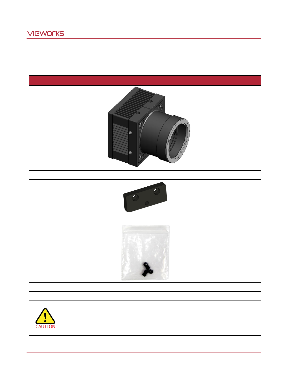
VA-29MC2-6 <F-Mount>
Mount Plate (Optional)
M5 Set Screws for Tilt Adjustment (Provided only with F-mount camera)
You can adjust the tilt using the M5 set screws, however it is not recommended since it is
adjusted as factory default settings.
If the tilt settings need to be adjusted inevitably, please contact your local dealer or factory
representative for technical support.
4 Package Components
Page 8 of 78 VW40-158-009
Page 9

VA-29MC2-6
5 Product Specifications
5.1 Overview
VA-29MC2-6, a Progressive Scan high performance CCD camera, is a new model of industrial proven VA
Camera Link series. Equipped with the Vieworks’ innovative technologies proved by world’s top FPD
manufacturers, VA-29MC2-6 offers not only high uniformed images but also high speed image processing
capabilities. This camera supports 29 megapixel resolution with frame rate up to 6.1 fps. Featured with high
quality image uniformity and high resolution, the camera is ideal for demanding applications such as FPD, PCB,
and semiconductor inspections.
Main Features
29 Megapixel Resolution
Area Of Interest(AOI)
Trigger Mode
Binning Mode – 2 × 2 / 4 × 4
Output Pixel Format – 8 / 10 / 12 bit
Sensor Output Channel – 1 Tap / 2 Tap / 4 Tap
Auto Tap Adjustment
Electronic Shutter – Global Shutter
Strobe Output
Analog Gain Adjustment
Analog Offset Adjustment
Look Up Table
Defective Pixel Correction
Flat Field Correction
Test Image
Image Invert
RS-644 Serial Communication
Temperature Monitor
Field Upgradable Firmware
Camera Link Base/Medium Configuration
Page 9 of 78 VW40-158-009
Page 10
VA-29MC2-6
VA Series
VA-29MC2-6
Active Image (H x V)
6576 × 4384
Sensor
ON Semiconductor KAI-29050
Pixel size
5.5 ㎛ × 5.5 ㎛
Sensor Output
1, 2 or 4 Tap Output
Video Output
8/10/12 bits, 2 Tap (Interleaved or Top & Bottom) or 4 Tap
Camera Interface
Camera Link (Base/Medium)
Electronic Shutter
Global Shutter
Max. Frame Rate at Full Resolution
Normal Speed: 4.8 fps (CL Base)
High Speed: 6.1 fps (CL Medium)
Camera Link
Pixel Clock
1, 2 Tap
Normal: 40 ㎒ / High: 52 ㎒
4 Tap
Normal: 80 ㎒ (CL Base) / High: 52 ㎒ (CL Medium)
Exposure Time
1 ㎲ ~ 60 s (10 ㎲ step)
Partial Scan (Max. Speed)
18 fps at 1000 Lines
Gamma Correction
User defined LUT(Look Up Table)
Black Offset
Adjustable (0 ~ 127 LSB at 12 bit, 256 step)
Video Gain
Analog Gain: 0 ~ 32 ㏈, 900 step
Trigger Mode
Mode (Free-Run, Standard, Overlap, Fast, Double)
Programmable exposure time and trigger polarity
External Trigger
External, 3.3 V – 24.0 V, 10 ㎃, optically isolated
Software Trigger
Camera Link CC1, Programmable Exposure
Dynamic Range
64 ㏈
Lens Mount
F-mount
Power
10 ~ 14 V DC, Typ. 9.5 W / Max. 12 W
Environmental
Operating: -5℃ ~ 40℃, Storage: -40℃ ~ 70℃
Mechanical
68 ㎜ 68 ㎜ 102 ㎜, 500 g (with F-mount)
5.2 Specifications
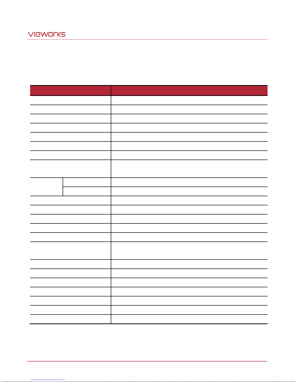
Technical specifications for VA-29MC2-6 are as follows:
Page 10 of 78 VW40-158-009
Table 5.1 Specifications of VA-29MC2-6
Page 11
VA-29MC2-6
KAI-0XX50
CCD
Sensor
14 bit
ADC
Timing
Generator
Image
Processing /
Control Logic
Micro
Controller
CCD Driver
FLASH SRAM
Trigger
Strobe
FPGA
14 Bit
Analog Front End
Camera -
Link
Interface
5.3 Camera Block Diagram
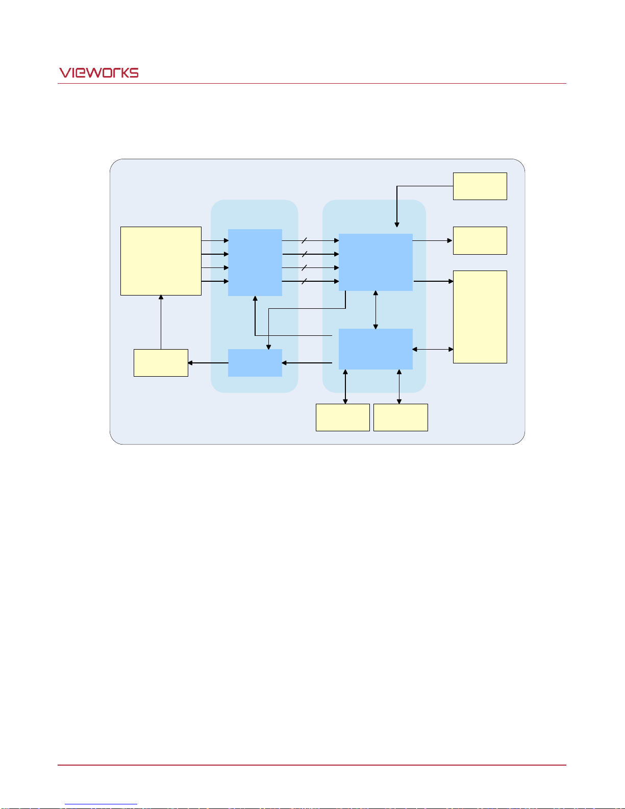
Figure 5.1 Camera Block Diagram
All controls and data processing of the camera are carried out in one FPGA chip. The FPGA generally consists
of a 32 bit RISC Micro-Controller and Processing & Control logic. The Micro-Controller receives commands from
the user through the Camera Link interface and then processes them. The FPGA controls the Timing Generators
and the Analog Front End (AFE) chips where the TG generates CCD control signals and AFE chips convert
analog CCD output to digital values to be accepted by the Processing & Control logic. The Processing & Control
logic processes the image data received from AFE and then transmits data through the Camera Link interface.
And also, the Processing & Control logic controls the trigger input and strobe output signals which are sensitive
to time. Furthermore, a SDRAM to process images and a Flash for operating Micro-Controller are installed
outside FPGA.
Page 11 of 78 VW40-158-009
Page 12
VA-29MC2-6
5.4 Spectral Response
5.4.1 Mono Camera Spectral Response
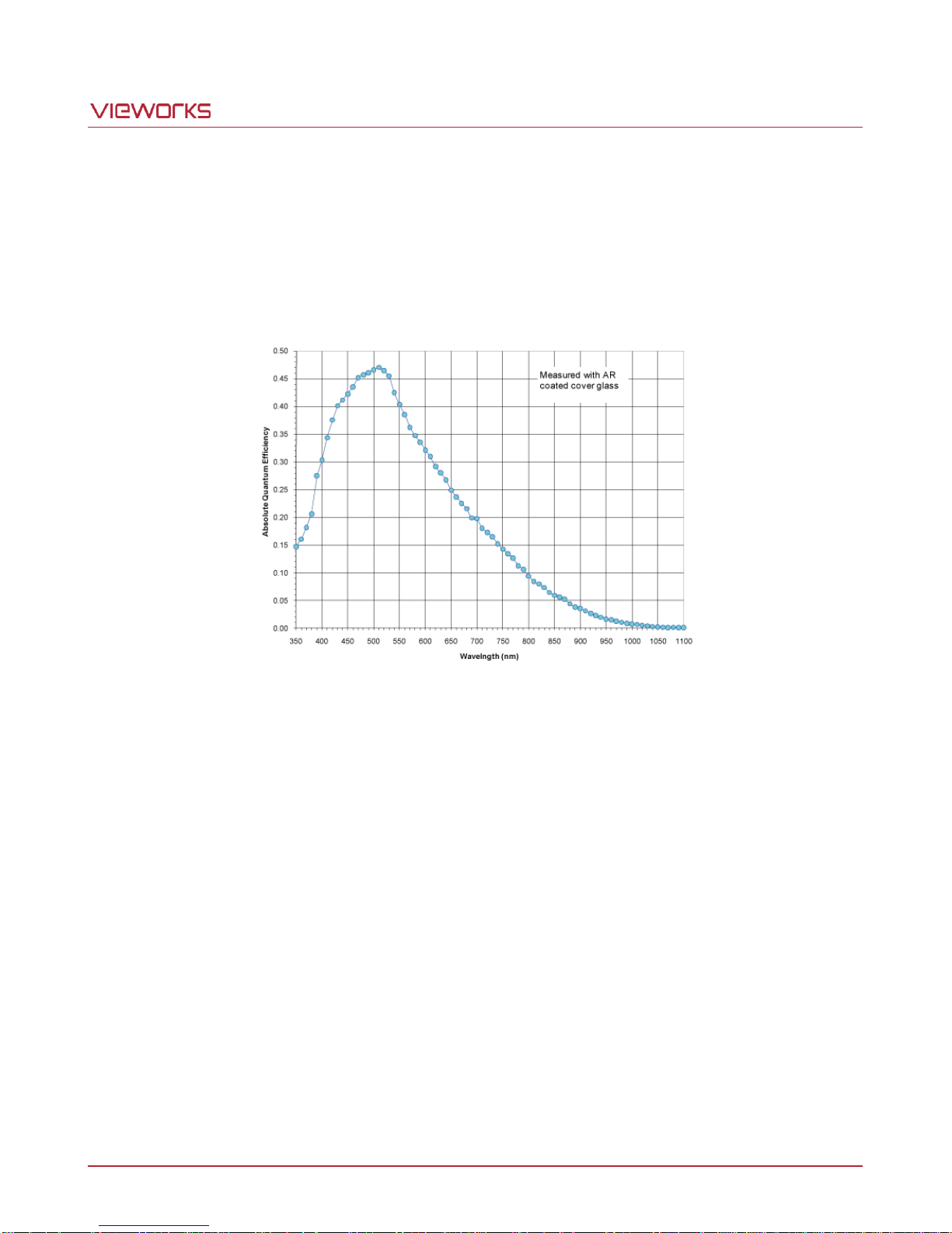
The following graph shows the spectral response for a VA-29MC2-6 monochrome camera.
Figure 5.2 VA-29MC2-M6 Spectral Response
Page 12 of 78 VW40-158-009
Page 13
VA-29MC2-6
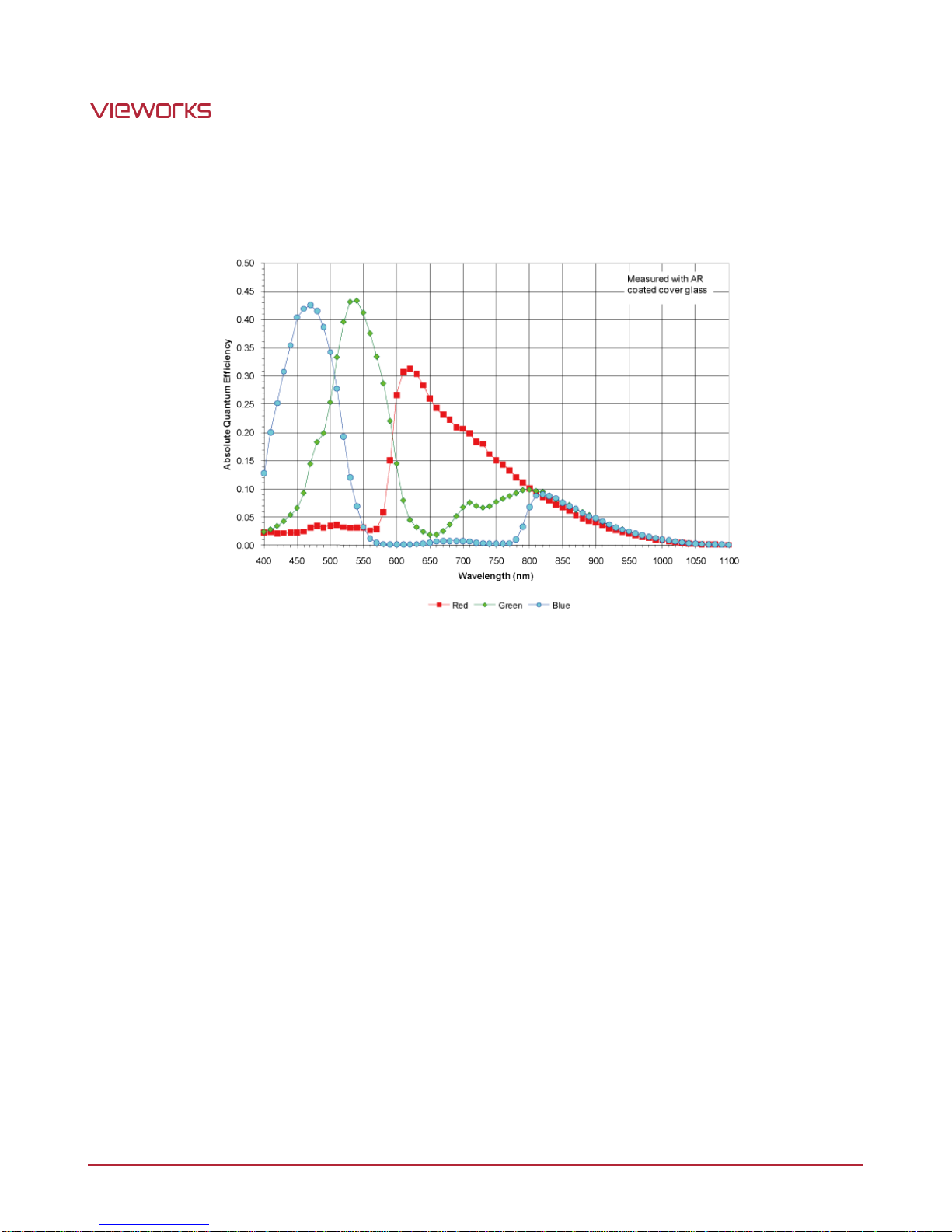
5.4.2 Color Camera Spectral Response
The following graph shows the spectral response for a VA-29MC2-6 color camera.
Figure 5.3 VA-29MC2-C6 Spectral Response
Page 13 of 78 VW40-158-009
Page 14
VA-29MC2-6
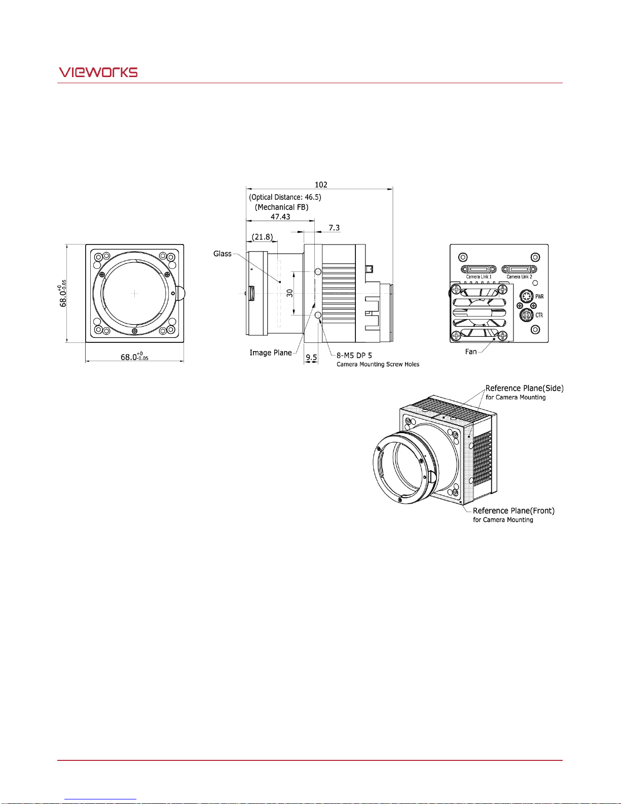
5.5 Mechanical Specification
The camera dimensions in millimeters are shown in the following figure.
Figure 5.4 VA-29MC-6 Mechanical Dimension
Page 14 of 78 VW40-158-009
Page 15
VA-29MC2-6
6 Connecting the Camera
The following instructions assume that you have installed a Camera Link frame grabber in your computer
including related software. For more information, refer to your Camera Link frame grabber user manual.
To connect the camera to your computer, follow the steps below:
1. Make sure that the power supply is not connected to the camera and your computer is turned off.
2. Plug one end of a Camera Link cable into the Camera Link connector on the camera and the other end of
the Camera Link cable into the Camera Link frame grabber in your computer.
3. Connect the plug of the power adapter to the power input receptacle on the camera.
4. Plug the power adapter into a working electrical outlet.
5. Verify all the cable connections are secure.
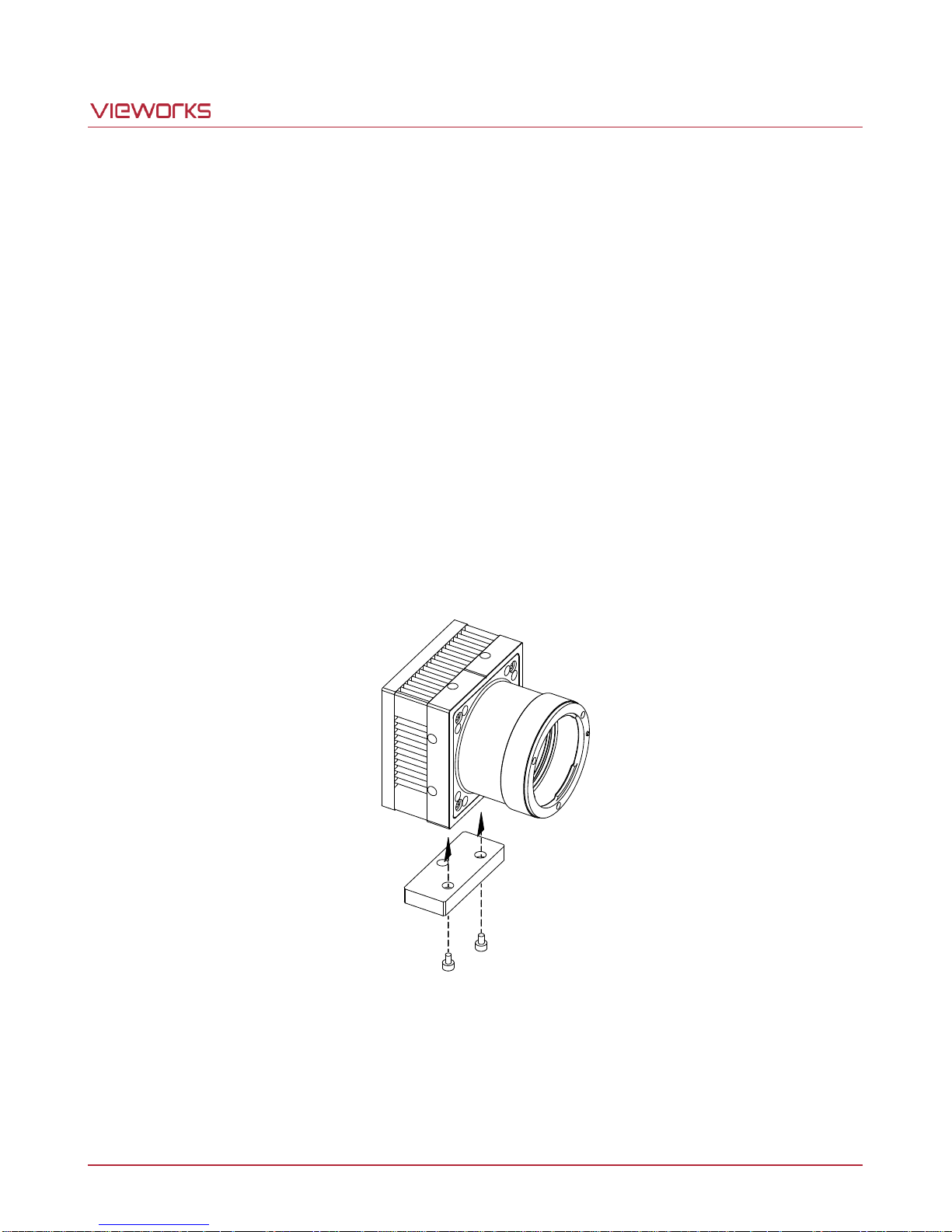
6.1 Mount Plate
The Mount Plate is provided as an optional item.
The camera can be fixed without using the Mount Plate.
Page 15 of 78 VW40-158-009
Page 16

VA-29MC2-6
6.2 Precaution to Center the Imaging Sensor
Users do not need to center the imaging sensor as it is adjusted as factory default settings.
When you need to adjust the center of the imaging sensor, please contact your local dealer or the
manufacturer for technical assistance.
6.3 Precaution about Blurring Compared to Center
Users do not need to adjust the tilt as it is adjusted as factory default settings.
If the tilt settings need to be adjusted inevitably, please contact your local dealer or factory representative for
technical support.
6.4 Installing the Configurator
You can control the camera by executing the Configurator.exe file.
You can download the latest Configurator at http://www.vieworks.com.
Refer to your Camera Link frame grabber user manual.
Page 16 of 78 VW40-158-009
Page 17
VA-29MC2-6
CAMERA LINK 1
1
13
26
14
①
②
③
⑤
④
7 Camera Interface
7.1 General Description
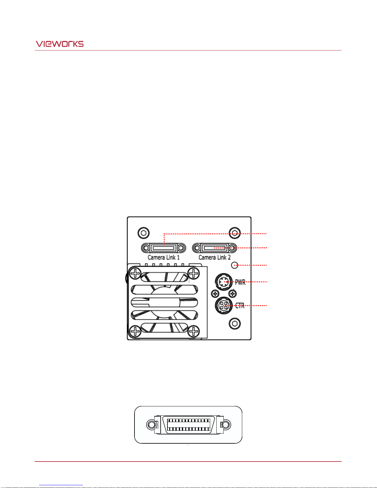
As shown in the figure below, 4 types of connectors and a status indicator LED are located on the back of the
camera and have the functions as follows:
26-pin Camera Link Connector 1 (Base): transmits video data and controls the camera.
26-pin Camera Link Connector 2 (Medium): transmits video data.
Status LED: displays power status and operation mode.
6-pin Power Input Receptacle: supplies power to the camera.
4-pin Control Receptacle: inputs external trigger signal and outputs strobe.
7.2 Camera Link Connector
Page 17 of 78 VW40-158-009
Figure 7.1 VA-29MC2-6 Back Panel
Figure 7.2 Camera Link Connector
Page 18
VA-29MC2-6
PAIR List
Pin
Signal Name
Type
Description
PAIR 0
1
Ground
Ground
Cable Shield
14
Ground
Ground
Cable Shield
PAIR 1
2
-X0
LVDS - Out
Camera Link Transmitter
15
+X0
LVDS - Out
Camera Link Transmitter
PAIR 2
3
-X1
LVDS - Out
Camera Link Transmitter
16
+X1
LVDS - Out
Camera Link Transmitter
PAIR 3
4
-X2
LVDS - Out
Camera Link Transmitter
17
+X2
LVDS - Out
Camera Link Transmitter
PAIR 4
5
-X3
LVDS - Out
Camera Link Transmitter
18
+X3
LVDS - Out
Camera Link Transmitter
PAIR 5
6
-XCLK
LVDS - Out
Camera Link Transmitter
19
-XCLK
LVDS - Out
Camera Link Transmitter
PAIR 6
7
- SerTC
LVDS - In
Serial Data Receiver
20
+ SerTC
LVDS - In
Serial Data Receiver
PAIR 7
8
- SerTFG
LVDS - Out
Serial Data Transmitter
21
+ SerTFG
LVDS - Out
Serial Data Transmitter
PAIR 8
9
- CC 1
LVDS - In
Software External Trigger
22
+ CC 1
LVDS - In
Software External Trigger
PAIR 9
10
N/C
N/C
N/C
23
N/C
N/C
N/C
PAIR 10
11
N/C
N/C
N/C
24
N/C
N/C
N/C
PAIR 11
12
N/C
N/C
N/C
25
N/C
N/C
N/C
PAIR 12
13
Ground
Ground
Cable Shield
26
Ground
Ground
Cable Shield
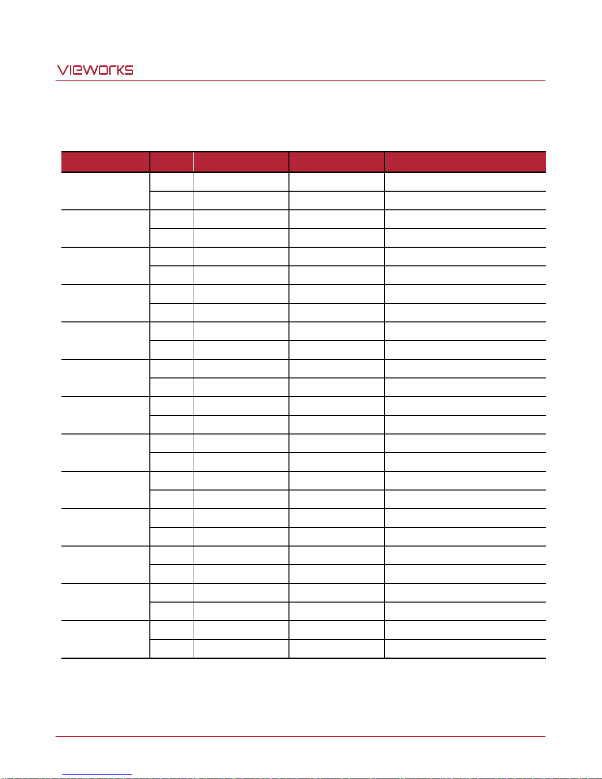
Camera Link connector complies with Camera Link Standard and the following list shows the pin configuration of
the connector.
Table 7.1 Pin Assignments for Camera Link Connector 1
Page 18 of 78 VW40-158-009
Page 19
VA-29MC2-6
PAIR List
Pin
Signal Name
Type
Description
PAIR 0
1
Ground
Ground
Cable Shield
14
Ground
Ground
Cable Shield
PAIR 1
2
-Y0
LVDS - Out
Camera Link Transmitter
15
+Y0
LVDS - Out
Camera Link Transmitter
PAIR 2
3
-Y1
LVDS - Out
Camera Link Transmitter
16
+Y1
LVDS - Out
Camera Link Transmitter
PAIR 3
4
-Y2
LVDS - Out
Camera Link Transmitter
17
+Y2
LVDS - Out
Camera Link Transmitter
PAIR 4
5
-YCLK
LVDS - Out
Camera Link Transmitter
18
+YCLK
LVDS - Out
Camera Link Clock Tx
PAIR 5
6
-Y3
LVDS - Out
Camera Link Channel Tx
19
+Y3
LVDS - Out
Camera Link Channel Tx
PAIR 6
7 - Not Used
Connected with 100 ohm
20 - Not Used
PAIR 7
8
-Z0
LVDS - Out
Camera Link Transmitter
21
+Z0
LVDS - Out
Camera Link Transmitter
PAIR 8
9
-Z1
LVDS - Out
Camera Link Transmitter
22
+Z1
LVDS - Out
Camera Link Transmitter
PAIR 9
10
-Z2
LVDS - Out
Camera Link Transmitter
23
+Z2
LVDS - Out
Camera Link Transmitter
PAIR 10
11
-ZCLK
LVDS - Out
Camera Link Transmitter
24
+ZCLK
LVDS - Out
Camera Link Clock Tx
PAIR 11
12
-Z3
LVDS - Out
Camera Link Channel Tx
25
+Z3
LVDS - Out
Camera Link Channel Tx
PAIR 12
13
Ground
Ground
Cable Shield
26
Ground
Ground
Cable Shield
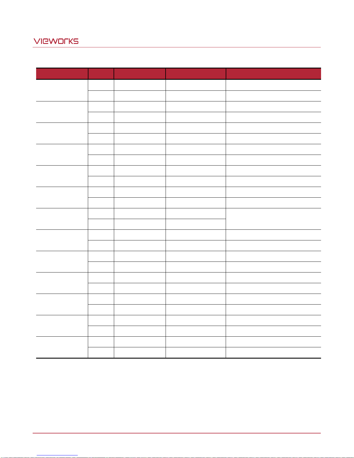
Table 7.2 Pin Assignments for Camera Link Connector 2
Page 19 of 78 VW40-158-009
Page 20
VA-29MC2-6
Sensor Output
CL Pixel Clock
CL Output
CL Configuration
CL Connector1
CL Connector2
1 Tap
40 ㎒ (Normal)
2 Tap
Base
52 ㎒ (High)
2 Tap
Base
2 Tap
40 ㎒ (Normal)
2 Tap
Base
52 ㎒ (High)
2 Tap
Base
4 Tap
80 ㎒ (Normal)
2 Tap
Base
52 ㎒ (High)
4 Tap
Medium
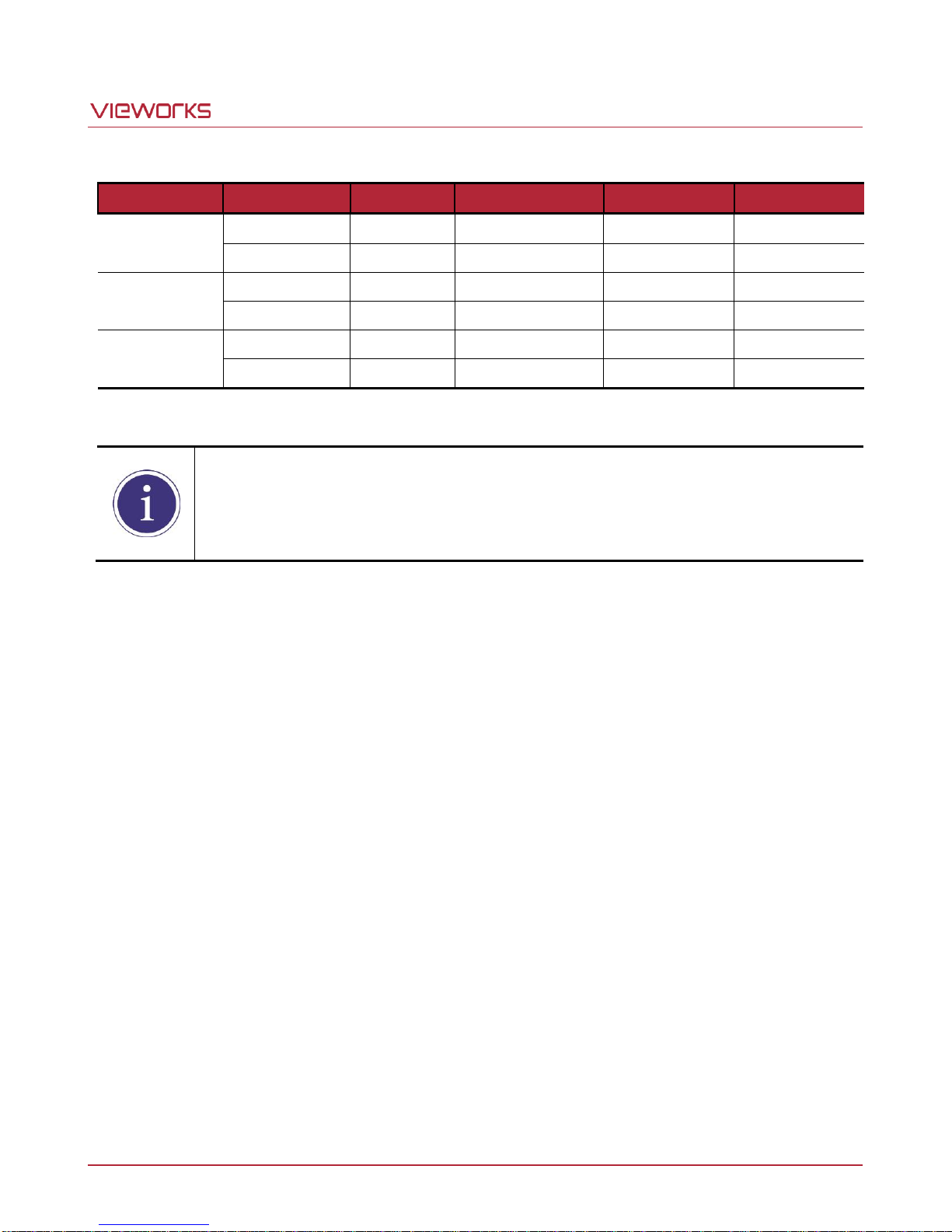
When you connect a Frame Grabber to the camera using Camera Link cables, make sure you
connect to the correct Camera Link connector. Incorrect connection of Connector 1 and
Connector 2 may cause malfunction of the camera or communication problems between the
camera and user’s computer.
Table 7.3 CL Connector Connections depending on the Channel mode and CL Pixel Clock
Page 20 of 78 VW40-158-009
Page 21
VA-29MC2-6
Pin Number
Signal
Type
Description
1, 2, 3
+ 12V DC
Input
DC Power Input
4, 5, 6
DC Ground
Input
DC Ground
Make sure the power is turned off before connecting the power cord to the camera.
Otherwise, damage to the camera may result.
If the voltage applied to the camera is greater than specified in the specifications,
damage to the camera may result.
1
2
3 4
5
6
7.3 Power Input Receptacle
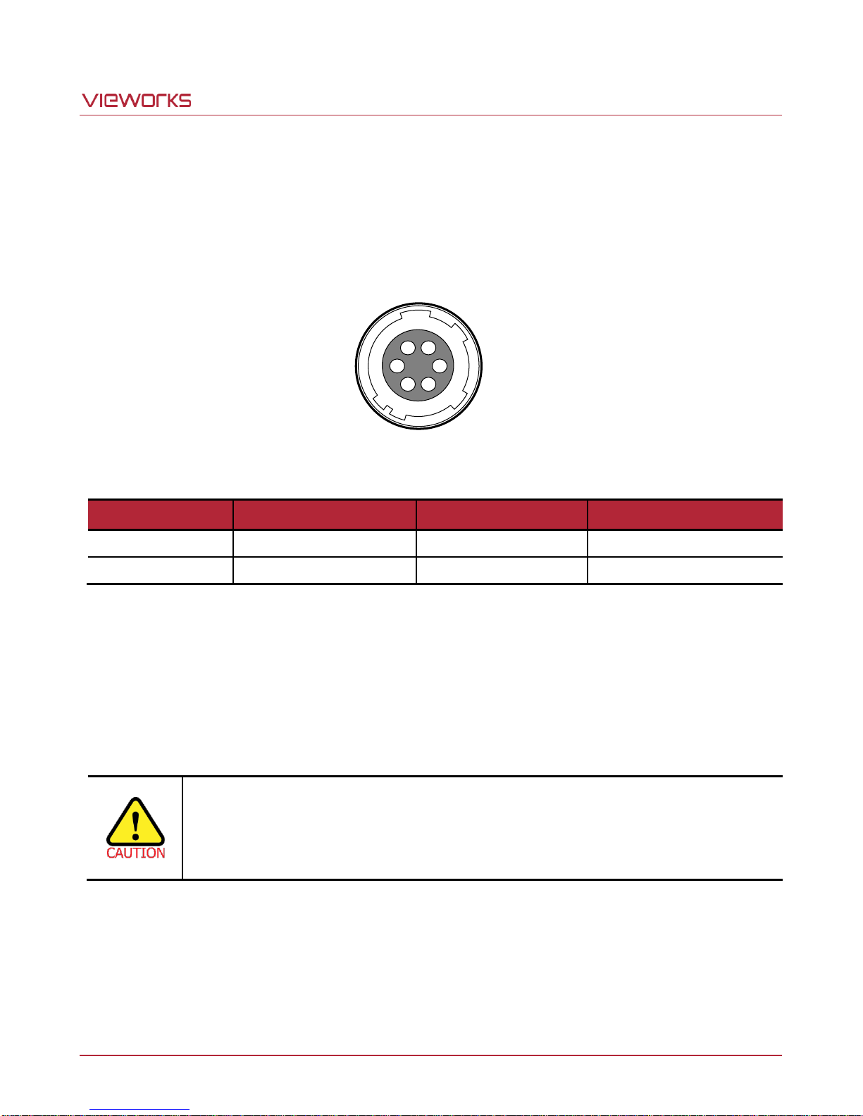
The power input receptacle is a Hirose 6-pin connector (part # HR10A-7R-6PB). The pin assignments and
configurations are as follows:
Figure 7.3 Pin Assignments for 6-pin Power Input Receptacle
Table 7.4 Pin Configuration for Power Input Receptacle
The mating connector is a Hirose 6-pin plug (part # HR10A-7P-6S) or the equivalent connectors. The power
adapter is recommended to have at least 1 A current output at 12 V DC ±10% voltage output (Users need to
purchase the power adapter separately).
Precaution for Power Input
Page 21 of 78 VW40-158-009
Page 22
VA-29MC2-6
1
2
4
3
Pin Number
Signal
Type
Description
1
Trigger Input +
Input - 2
Trigger Input -
Input - 3
DC Ground
-
DC Ground
4
Strobe Out
Output
3.3 V TTL Output
Output resistance: 47 Ω
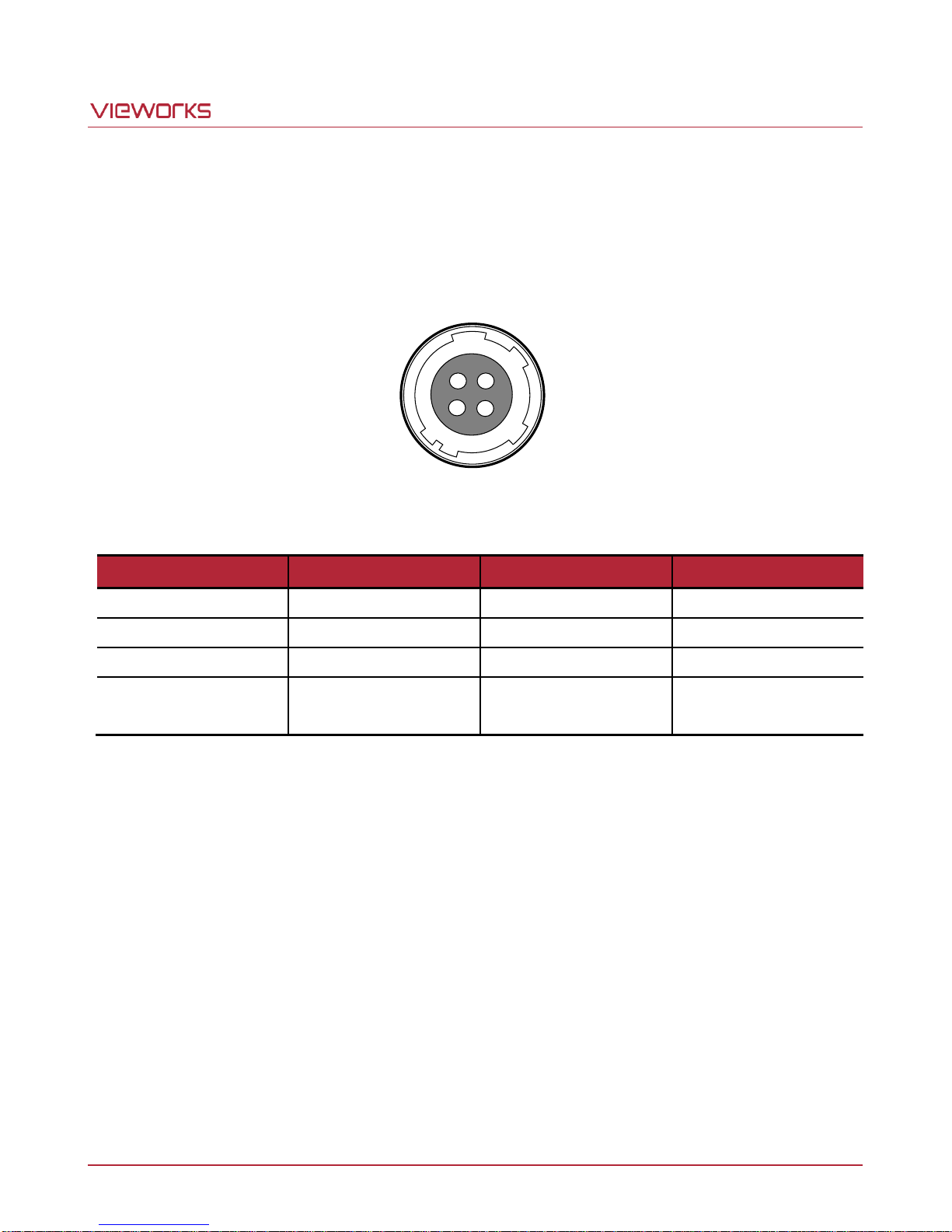
7.4 Control I/O Receptacle
The control I/O receptacle is a Hirose 4-pin connector (part # HR10A-7R-4S) and consists of an external trigger
signal input and strobe output ports. The pin assignments and configurations are as follows:
Figure 7.4 Pin Assignments for Control I/O Receptacle
Table 7.5 Pin Configurations for Control I/O Receptacle
The mating connector is a Hirose 4-pin plug (part # HR10A-7P-4P) or the equivalent connectors.
Page 22 of 78 VW40-158-009
Page 23
VA-29MC2-6
TRIGGER_IN + 1
2
3
4
HR10A-7R-4SB
330 Ω
PHOTO COUPLER
TRIGGER+
+5V
1 kΩ
USER
TRIGGER-
Camera
3.3 ~ 5 V
0 V
TTL Driver
0 V
3.3 V
Strobe_Out +
Strobe_Out -
47 O
Strobe Out
TTL Driver
1
2
3
4
HR10A-7R-4SB
Camera
USER
( Output Current : ? 12 mA )
3.3V TTL Driver IC (NC7S14)
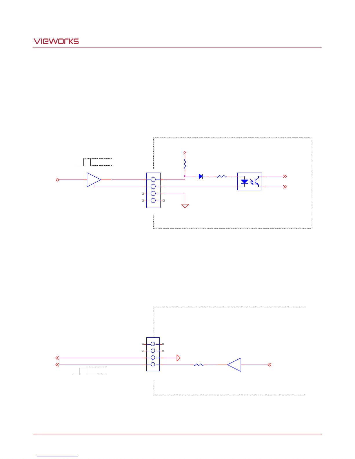
7.5 Trigger Input Circuit
The following figure shows trigger signal input circuit of the 4-pin connector. Transmitted trigger signal is applied
to the internal circuit through a photo coupler. The minimum trigger width that can be recognized by the camera
is 1 ㎲. If transmitted trigger signal is less than 1 ㎲, the camera will ignore the trigger signal. An external trigger
circuit example is shown below.
7.6 Strobe Output Circuit
The strobe output signal comes out through a 3.3 V output level of TTL Driver IC. A pulse width of the signal is
synchronized with an exposure (shutter) signal of the camera.
Page 23 of 78 VW40-158-009
Figure 7.5 Trigger Input Schematic
Figure 7.6 Strobe Output Schematic
Page 24
VA-29MC2-6
The AOI values (H × V) may vary depending on the type of Camera Link frame grabber. For
technical assistance, contact your local dealer or the factory representative.
Vertical
AOI
Area Of Interest
(0, VSIZE - 1)
H Start
H End
V Start
V End
(HSIZE - 1, VSIZE - 1)
(HSIZE - 1, 0)
(0, 0)
8 Camera Features
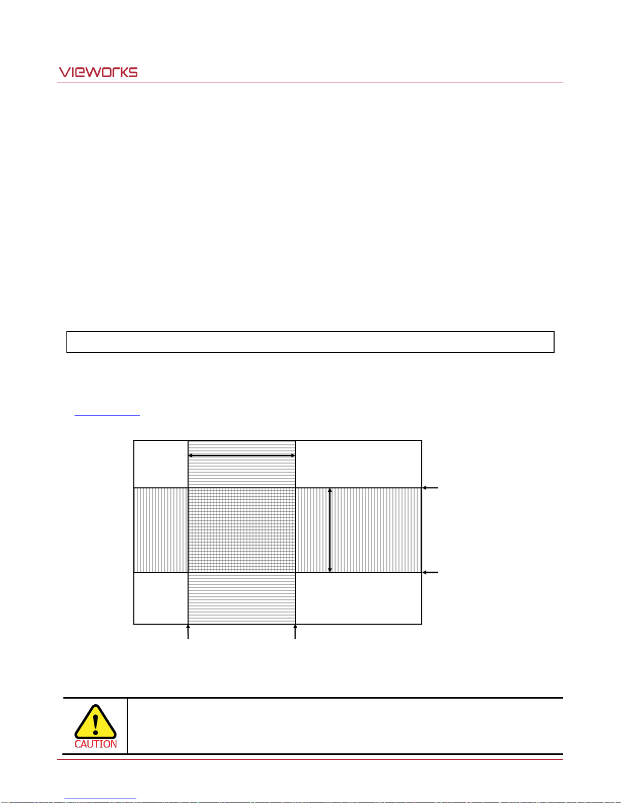
8.1 Area of Interest (AOI)
The Area of Interest (AOI) feature allows you to specify a portion of the sensor array. You can acquire only the
frame data from the specified portion of the sensor array while preserving the same quality as you acquire a
frame from the entire sensor array. AOI is determined as the overlapping area of two areas when designating
start point and end point in horizontal and vertical direction as shown in the figure below. Start point and End
point mean the starting and end of the AOI.
According to the characteristics of the imaging sensor structure, readout of the image will be proceeded at the
top and bottom simultaneously. When you try to set Vertical AOI with Channel mode set to 4 Tap, V End will be
ignored because V End is defined by V Start. The actual V End will be applied according to the following formula.
V End = (VSIZE - V Start) -1
The narrower Vertical AOI is designated, the faster the frame speed will be. However, Horizontal AOI does not
affect the frame speed. For more information about AOI parameter settings, see “sha” and “sva” commands in
the Command List.
Figure 8.1 AOI
Page 24 of 78 VW40-158-009
Page 25
VA-29MC2-6
VA-29MC2-6
CL Pixel Clock - Normal
CL Pixel Clock - High
T
VCCD
28.5 ㎲
TL(1 channel)
172.8 ㎲
134.5 ㎲
TL(2 channel)
90.6 ㎲
71.4 ㎲
TL(4 channel)
90.6 ㎲
71.4 ㎲
TFD
6.8 ㎲
V
SIZE
4384Lines
Minimum Vertical AOI Size
1000 Lines
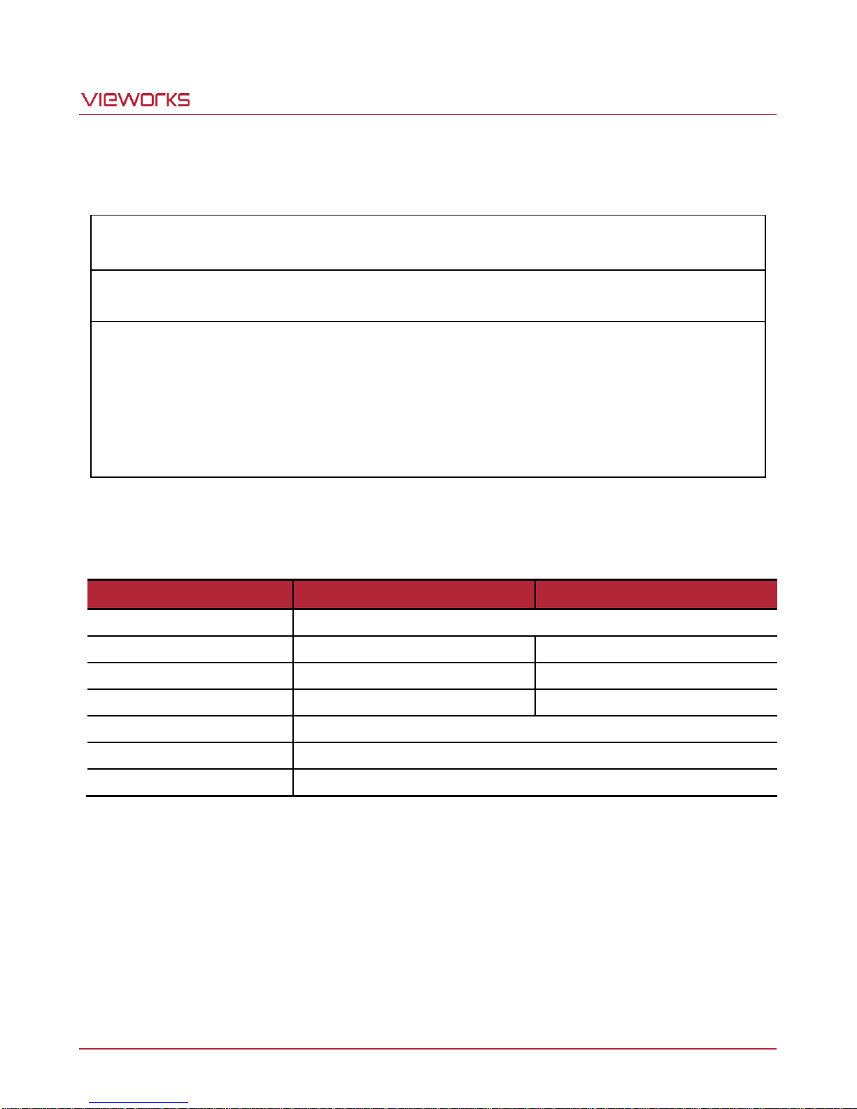
The approximate maximum frame speed depending on the change of Vertical AOI cab be determined as shown
in the following formula.
1 or 2 Channel Mode:
Frame Rate (fps)
=
1000000
/
[T
VCCD
+ TFD ×
{(V
SIZE
– V
) + 12)} + (V
AOI
+ 98) × TL]
AOI
4 Channel Mode:
Frame Rate (fps)
=
1000000
/
[T
VCCD
+ TFD ×
{(V
SIZE
–
V
AOI
)/2 +
12)} + {(V
/2 + 98) × TL}]
AOI
TVCCD : time required to move electric charges accumulated on pixels to Vertical
Register
TFD : time required for Fast Dump
VSIZE : number of vertical lines of CCD
TL : time required for transmission of one line
VAOI : size of Vertical AOI
The available minimum values of T
VCCD
, TFD, V
, TL and V
SIZE
are as shown in the table below. The value of TL
AOI
may vary depending on the Channel mode.
Page 25 of 78 VW40-158-009
Table 8.1 Timing values for VA-29MC2-6
Page 26
VA-29MC2-6
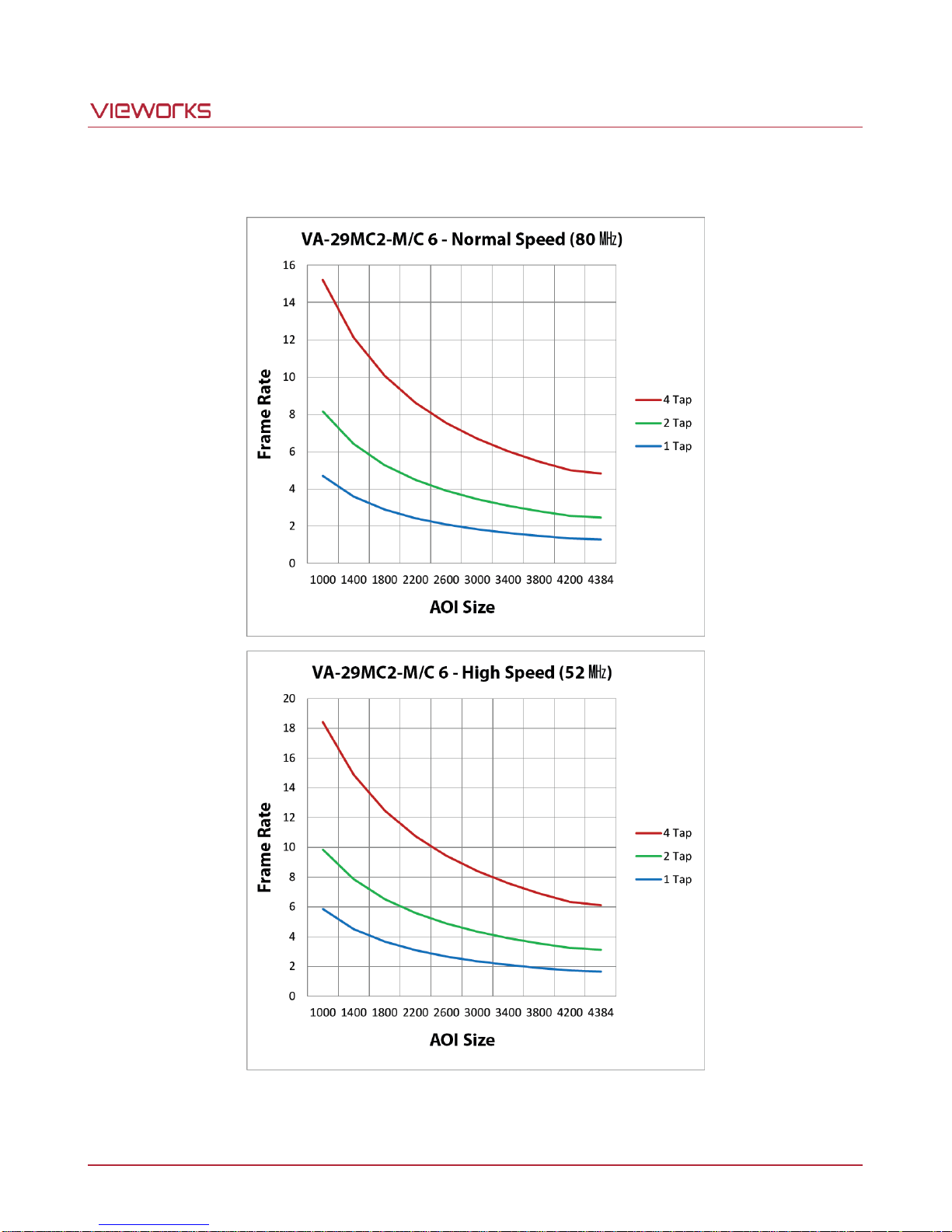
The following graph shows frame rate depending on Camera Link Pixel Clock and Vertica AOI changes.
Page 26 of 78 VW40-158-009
Figure 8.2 Frame Rate by VAOI changes
Page 27
VA-29MC2-6
Even if the binning is performed on the color camera, the resulting image will be monochrome.
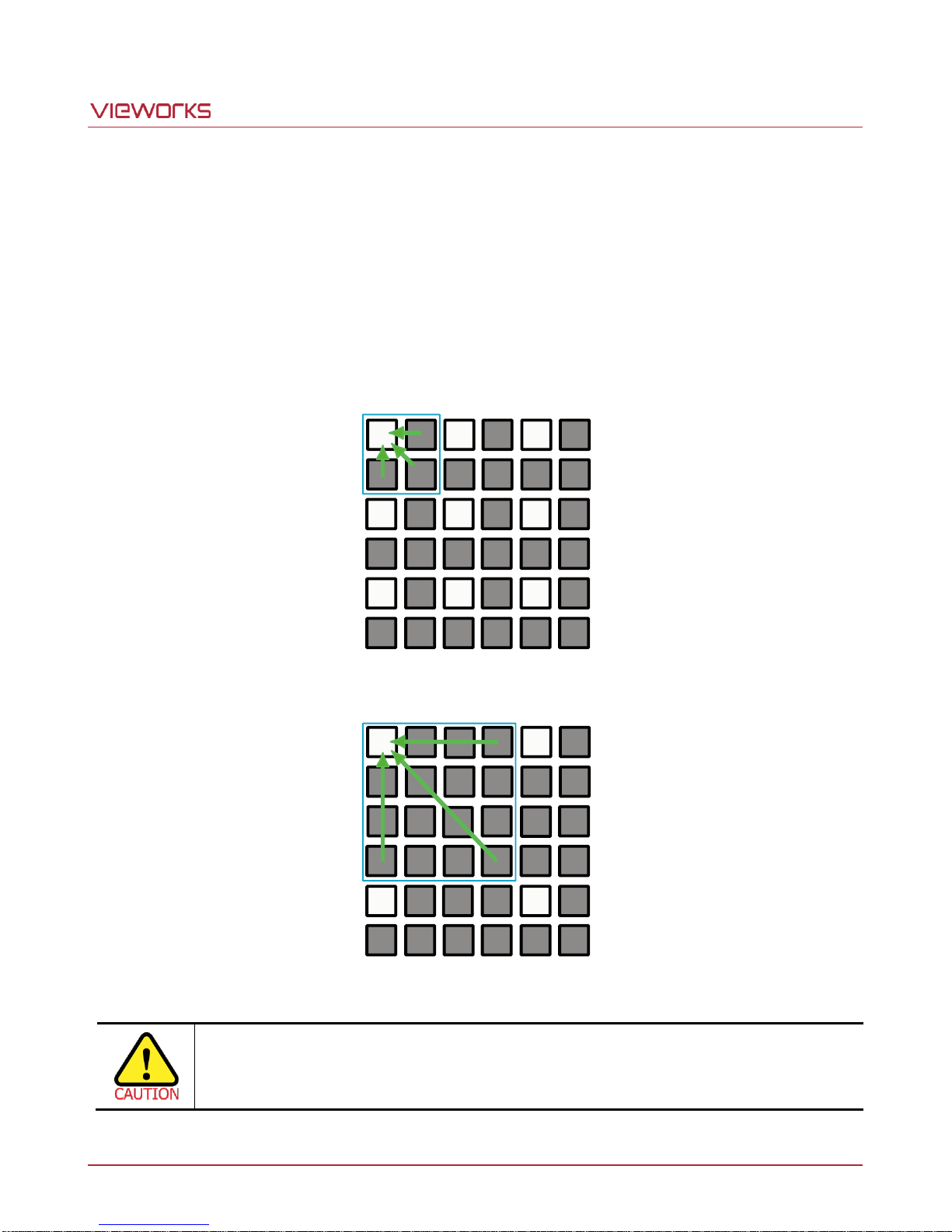
8.2 Binning
Binning has the effects of increasing the level value and decreasing resolution by summing the values of the
adjacent pixels and sending them as one pixel. VA-29MC2-6 provides two binning factors (×2, ×4) that users
can apply in either vertical, horizontal or both directions. The below figure shows application of 2 × 2 Binning
and 4 × 4 Binning respectively. Since vertical binning is processes in the internal register of CCD, the frame
rate will be increased as many as Binning Factor if the Binning is set, but horizontal binning does not affect the
frame rate. You can set the Binning Factor using the “sbf” command.
Figure 8.3 2 × 2 Binning
Figure 8.4 4 × 4 Binning
Page 27 of 78 VW40-158-009
Page 28

VA-29MC2-6
8.3 Trigger Mode
When the Trigger Mode is set to Free-Run, the camera will generate all required trigger signals internally, and
you do not need to apply trigger signals to the camera.
When the Trigger Mode is set to Standard, Fast, Double or Overlap, you must apply a trigger signal to the
camera each time you want to begin a frame acquisition. The Source parameter specifies the source signal that
will act as the trigger signal.
The available settings for the Source parameter are:
CC1: You can apply a trigger signal to the camera via Camera Link CC1 channel.
For more information, refer to your Camera Link frame grabber user manual.
Ext.: You can apply a trigger signal to the camera by injecting an externally generated electrical
signal (commonly referred to as a hardware trigger signal) into the Control I/O receptacle on
the camera.
If the Source parameter is set to CC1 or Ext., you must also set the Polarity parameter.
The available settings for the Polarity parameter are:
Active Low: Specifies that a falling edge of the electrical signal will act as the trigger signal.
Active High: Specifies that a rising edge of the electrical signal will act as the trigger signal.
Page 28 of 78 VW40-158-009
Page 29
VA-29MC2-6
8.3.1 Free-Run Mode
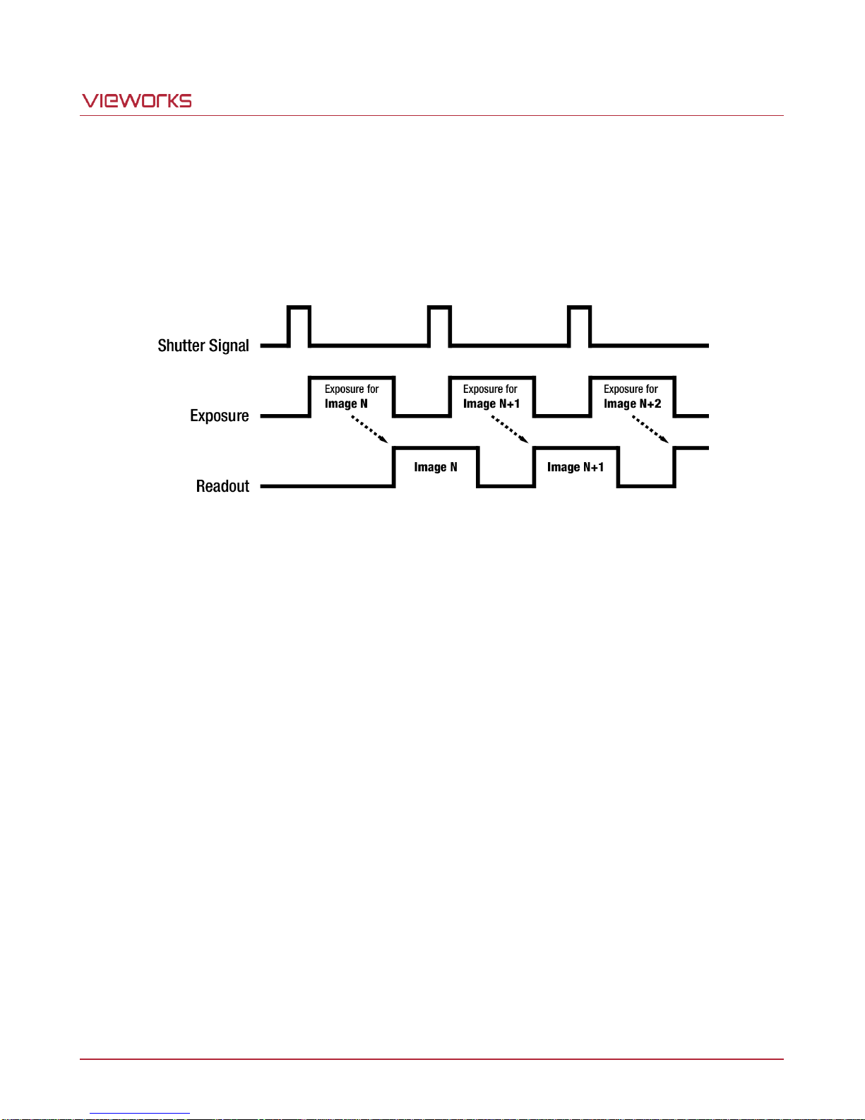
When the Trigger Mode is set to Free-Run, the camera will generate all required trigger signals internally. When
the camera is set this way, the exposure time for each frame acquisition is determined by the value of the
camera’s Exposure Time parameter. The camera will constantly acquire images (repeat exposure and readout)
without any need for triggering by the user.
Figure 8.5 Free-Run Mode
With the Trigger Mode set to Free-Run, the exposure for a new frame will overlap the readout for the previous
frame. The operation of the camera may differ depending on the length of the exposure time and readout time.
Page 29 of 78 VW40-158-009
Page 30
VA-29MC2-6
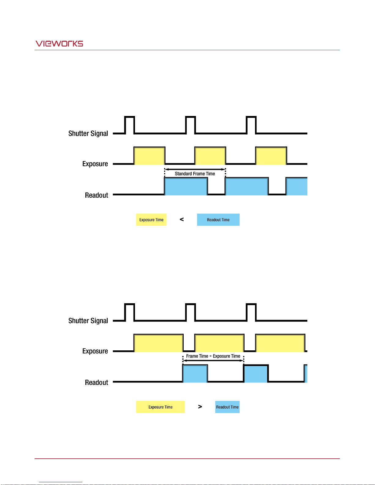
If the exposure time is shorter than the readout time, a shutter signal will be generated while reading out the
sensor data for the previously acquired frame. Then, the camera will begin reading out the sensor data for a new
frame as soon as it finishes reading out the sensor data for the previous frame. In this case, the frame speed will
be constant regardless of changes in the exposure time.
Figure 8.6 Exposure Time is shorter than Readout Time
If the exposure time is longer than the readout time, the camera will begin the process of reading out a frame
each time a shutter signal is generated. After completing the process of reading out the frame, the camera will
not begin the process of reading out a new frame until the camera completes the process of exposing a new
frame. In this case, the frame speed becomes slower as you increase the exposure time value.
Figure 8.7 Exposure Time is longer than Readout Time
Page 30 of 78 VW40-158-009
Page 31
VA-29MC2-6
8.3.2 Standard Mode
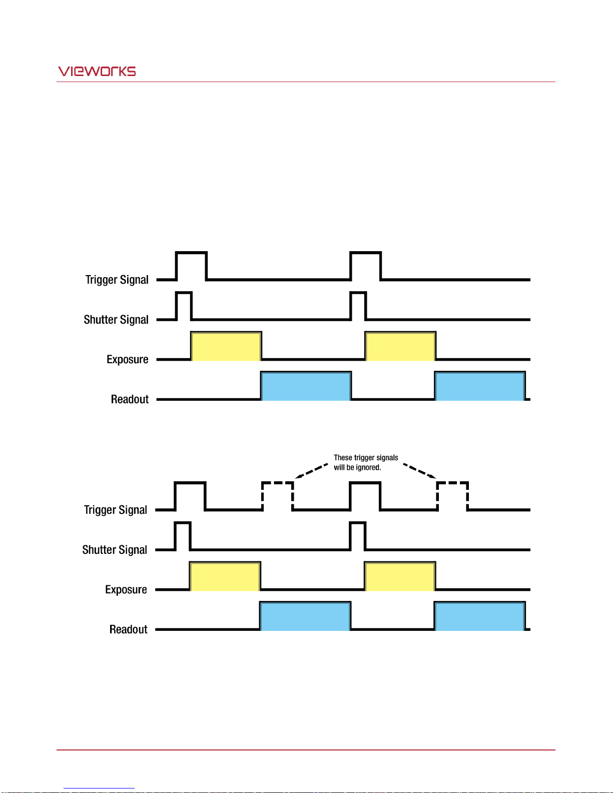
When the Trigger Mode is set to Standard, you must trigger exposure start by applying trigger signals to the
camera. Applying a trigger signal to the camera will exit the camera from the waiting for trigger signal acquisition
status and will begin the process of exposing and reading out a frame. After the readout for the frame is
complete and the camera is ready to accept another trigger signal, it will return to the waiting for trigger signal
acquisition status. Trigger signals applied to the camera when it is not in a waiting for trigger signal acquisition
status will be ignored.
Figure 8.8 Standard Mode
Figure 8.9 Trigger Ignored
Page 31 of 78 VW40-158-009
Page 32
VA-29MC2-6
8.3.3 Double
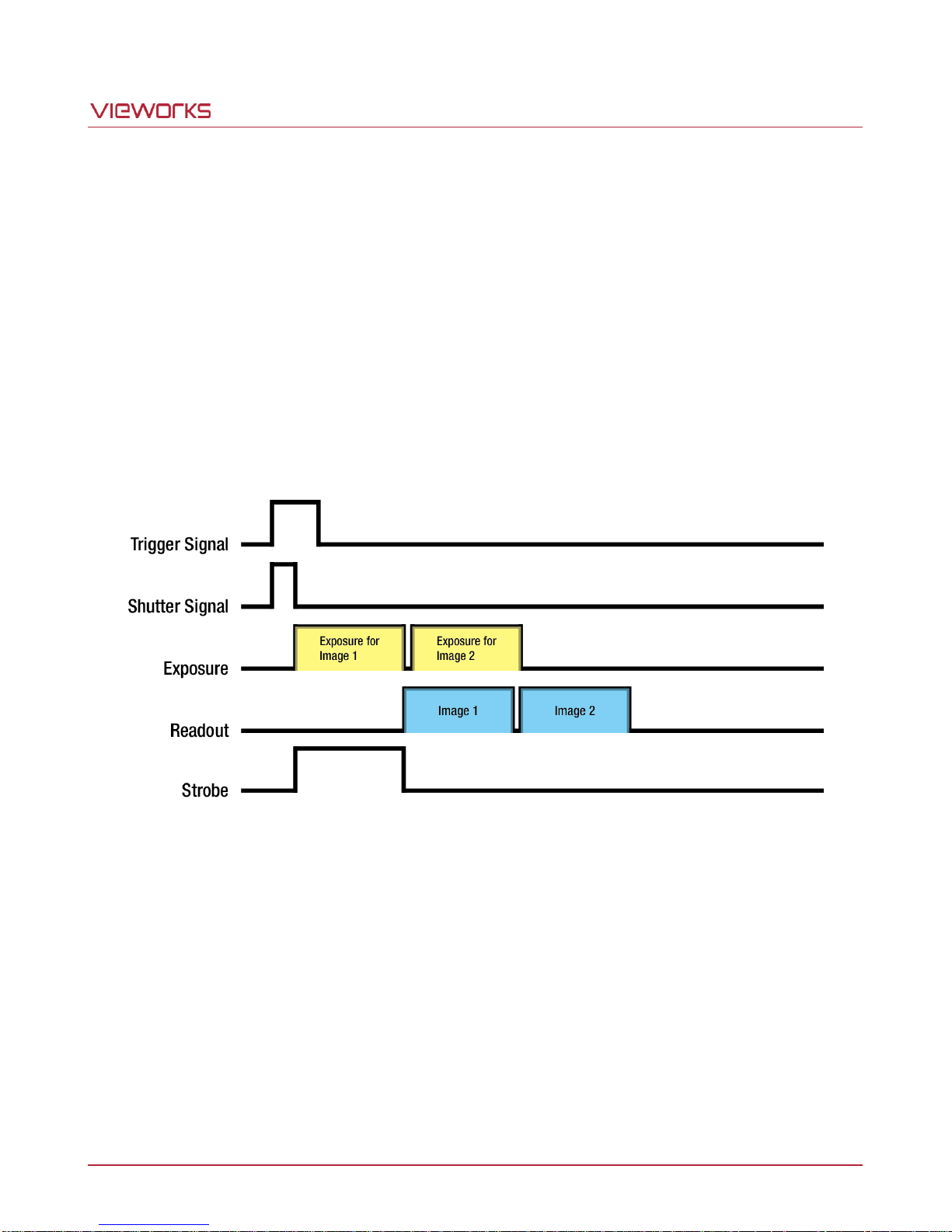
When the Trigger Mode is set to Double, two frames can be acquired with a single trigger signal. When a
trigger signal is applied to the camera, the camera begins the process of exposing the first frame according to
the current exposure time settings. Once the exposure for the first frame is complete, the camera reads out the
sensor data. At this point, the process of exposing the second frame begins. Then, the camera reads out the
sensor data for the second frame after reading out the sensor data for the previous frame.
In the Double mode, the exposure time for the second frame equals to the readout time of the first frame. There
is a just few microseconds (or dozen of microseconds) between the point where the exposure process for the
first frame ends and the point where the exposure process for the second frame begins. This is because the
camera does not generate a shutter signal while reading out the sensor data for the first frame. At this point, the
camera outputs a strobe out signal reflecting the exposure time for the first frame.
Page 32 of 78 VW40-158-009
Figure 8.10 Double Mode
Page 33
VA-29MC2-6
8.3.4 Fast Mode
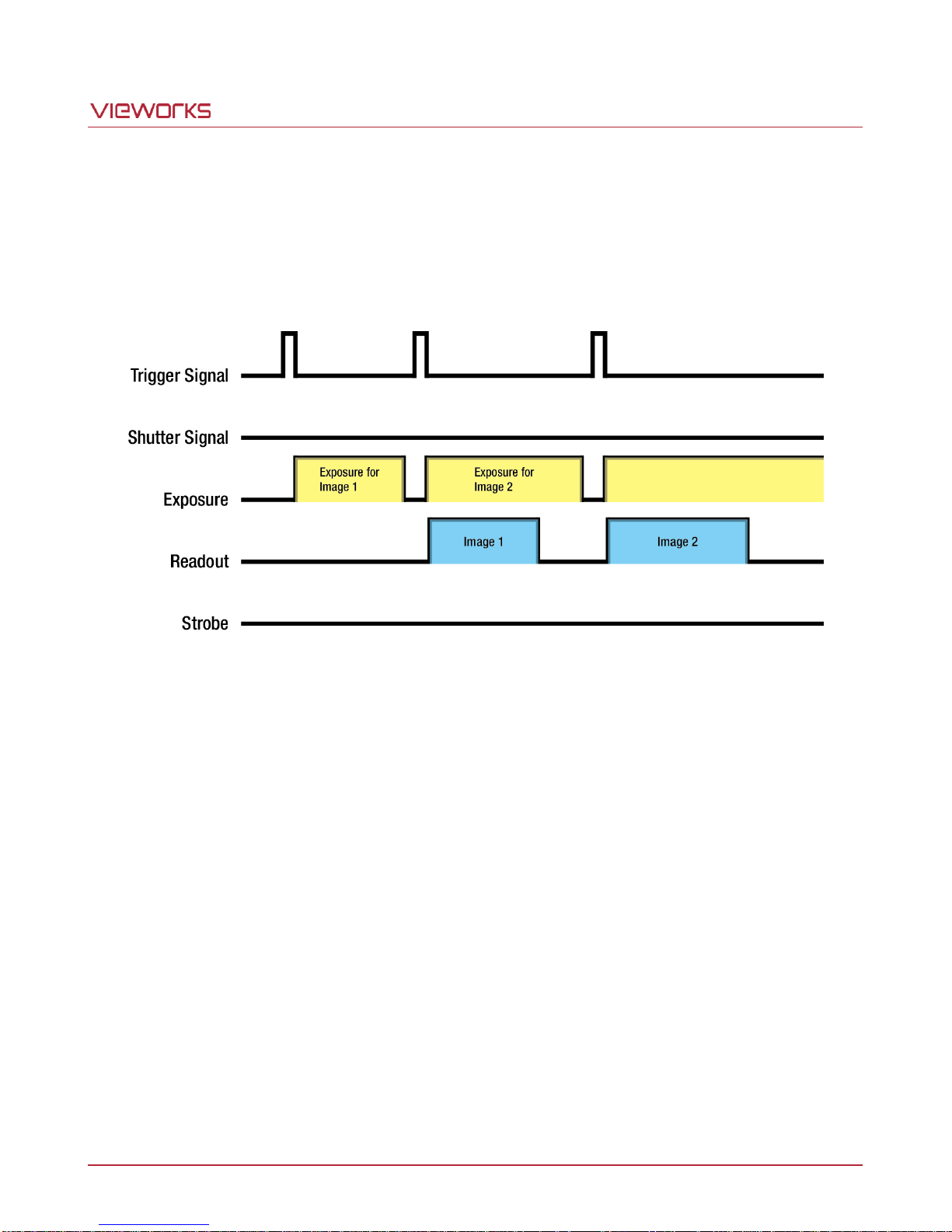
The Fast mode is useful to apply trigger signals with shorter interval than those in the Standard mode. In the
Fast mode, the camera begins the process of reading out the previous frame as soon as a new trigger signal is
applied to the camera. The trigger signal interval determines the exposure time for a frame since the camera
does not generate a shutter signal during the process of reading out a frame.
Figure 8.11 Fast Mode
Page 33 of 78 VW40-158-009
Page 34
VA-29MC2-6
Channel Mode
Readout Time
1 channel
603.0 ㎳
2 channel
320.2 ㎳
4 channel
163.6 ㎳
8.3.5 Overlap Mode
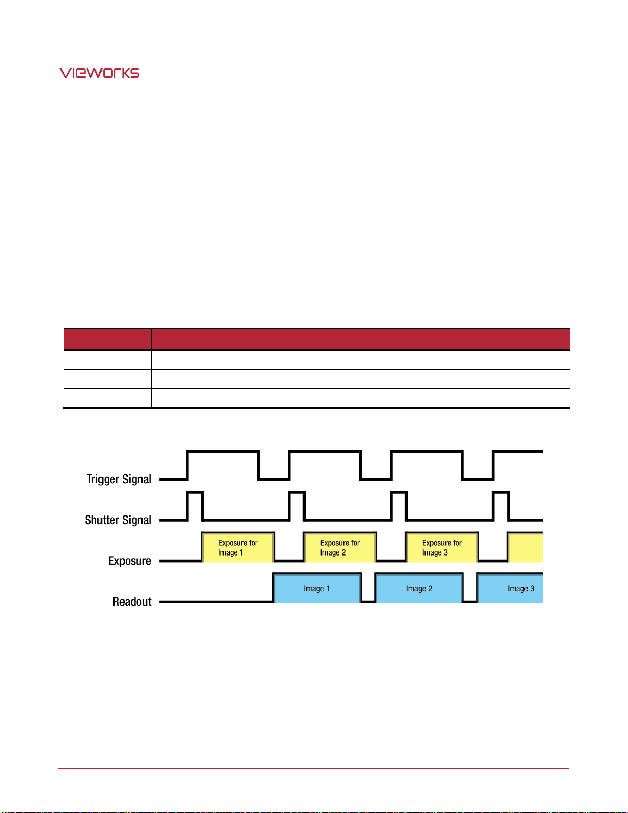
When the Trigger Mode is set to Overlap, the camera operates in the ‘overlapped’ mode which allows the
exposure for a new frame to overlap the sensor readout for the previous frame. When a new trigger signal is
applied to the camera while reading out the previous frame, the camera begins the process of exposing a new
frame. If you will be operating the camera with the Overlap mode, there are important guidelines to keep in mind:
You must not begin the exposure for a new frame while the exposure for the previous frame is in progress.
You must not end the exposure for the current frame until the readout for the previous frame is complete.
To acquire images with the maximum frame rate, the exposure time must not be longer than the readout
time and the trigger signal interval must not be shorter than the readout time.
The readout time varies depending on the Channel mode as shown in the following table.
Table 8.2 VA-29MC2-6 Readout Time
Figure 8.12 Overlap Mode
Page 34 of 78 VW40-158-009
Page 35
VA-29MC2-6
H x V
Active Pixels
B
G
G
R
B
G
G
R
B
G
G
R
B
G
G
R
B
G
G
R
B
G
G
R
B
G
G
R
B
G
G
R
Left Dark Columns
Right Dark Columns
Dark Rows
Buffer Rows
Buffer Rows
Left Buffer Columns
Right Buffer Columns
Video A Video B
Dummy
Pixels
Horizontal Register
Dark Rows
(1, 1)
Video C Top Horizontal Register Video D
Dummy
Pixels
Dummy
Pixels
Dummy
Pixels
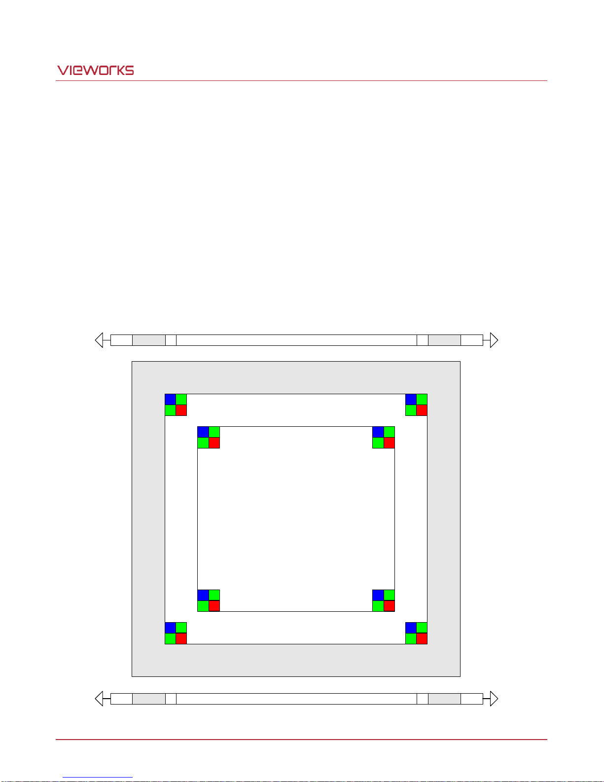
8.4 Channel Mode
The Channel mode determines how the image data in the horizontal register of the CCD will be read out.
The available settings are: 1 Tap (Single Channel), 2 Tap (Dual Channel) or 4 Tap (Quadrant Channel).
With the 1 Tap setting, all pixel values in the horizontal register will be read out from the left bottom Video
Amplifier (Video A). With the 2 Tap setting, pixel values from the left of the CCD will be read out from the Video A
and pixel values from the right of the CCD will be read out from the Video B. With 4 Tap setting, pixel values from
the left bottom of the CCD will be read out from the Video A, pixel values from the right bottom of the CCD will be
read out from the Video B, pixel values from the left top of the CCD will be read out from the Video C, and pixel
values from the right top of the CCD will be read out from the Video D. The advantage of the 4 Tap setting is that
it makes readout about four times faster than the 1 Tap setting. This is true because the four channels are used
simultaneously to read out the sensor.
Page 35 of 78 VW40-158-009
Figure 8.13 Channel Mode
Page 36
VA-29MC2-6
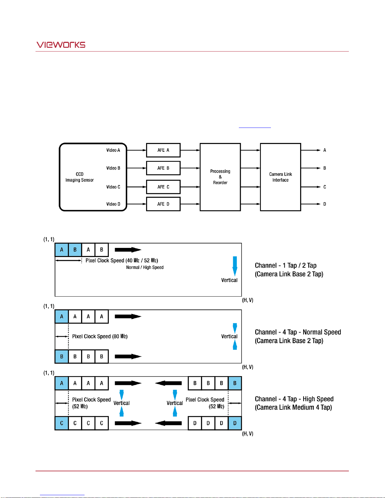
The image data read out from the CCD goes through image processing and it is reordered to be compliant with
the Camera Link standard. With the 1 Tap setting, image data read out from the Video A will be transmitted in a
Camera Link 2 Tap Interleaved fashion. With the 2 Tap setting, image data read out from the Video A and B
simultaneously will be transmitted in a Camera Link A, B 2 Tap Interleaved fashion. With the 4 Tap setting, image
data read out from the Video A, B, C and D simultaneously will be transmitted in a Camera Link 2 Tap Top and
Bottom (Normal Speed) or Camera Link Quadrant (High Speed) fashion (Figure 8.15).
Figure 8.14 Image Data Flow
Page 36 of 78 VW40-158-009
Figure 8.15 Data Output
Page 37
VA-29MC2-6
0
6
12
18
24
30
36
0
100
200
300
400
500
600
700
800
Gain(dB)
Gain Curve
Register Value
8.5 Gain and Offset
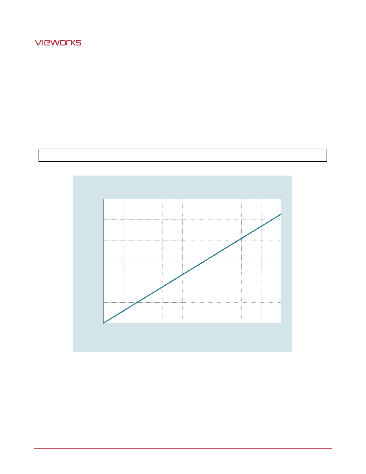
The camera has one Analog Signal Processor (or Analog Front End, AFE) for each channel. The AFE consists of
Correlated Double Sampler (CDS), Variable Gain Amplifier (VGA), Black Level Clamp and 12 bit A/D converter.
The AFE has a register designated for the Gain and Offset values. You can adjust the Gain and Offset values by
entering a proper value in the register. The Gain value can be set in a range from 0 to 899. If you know the
current setting value for the Gain, you can use the formula below to calculate the actual Gain (㏈).
Gain(㏈) = (setting value × 0.035㏈)
The Offset value can be set in a range from 0 to 255 (LSB).
Page 37 of 78 VW40-158-009
Figure 8.16 Register Setting Values for the Actual Gain Values
Page 38

VA-29MC2-6
12-bit Data
4096 entry
Lookup Table
12-bit Data
LUT
0
500
1000
1500
2000
2500
3000
3500
4000
0 500 1000 1500 2000 2500 3000 3500 4000
Input Level
Output Level
8.6 LUT
LUT (Lookup Table) converts original image values to certain level values. Since it is mapped one to one for
each level value, 12 bit output can be connected to 12 bit input. LUT is in the form of table that has 4096 entries
from 0 to 4095 and the camera provides 2 non-volatile spaces for LUT data storage. You can determine whether
to apply LUT and which LUT to use by using the “sls" command. For more information about how to download
LUT to the camera, refer to Appendix B.
Figure 8.17 LUT Block
Page 38 of 78 VW40-158-009
Figure 8.18 LUT at Gamma 0.5
Page 39
VA-29MC2-6
L3 L2 L1 R1 R2 R3
<Current Pixel>
Adjacent Defect Pixel (s)
Correction Value of Current Pixel
None
(L1 + R1) / 2
L1
R1
R1
L1
L1, R1
(L2 + R2 ) / 2
L1, R1, R2
L2
L2, L1, R1
R2
L2, L1, R1, R2
(L3 + R3) / 2
L2, L1, R1, R2, R3
L3
L3, L2, L1, R1, R2
R3
8.7 Defective Pixel Correction
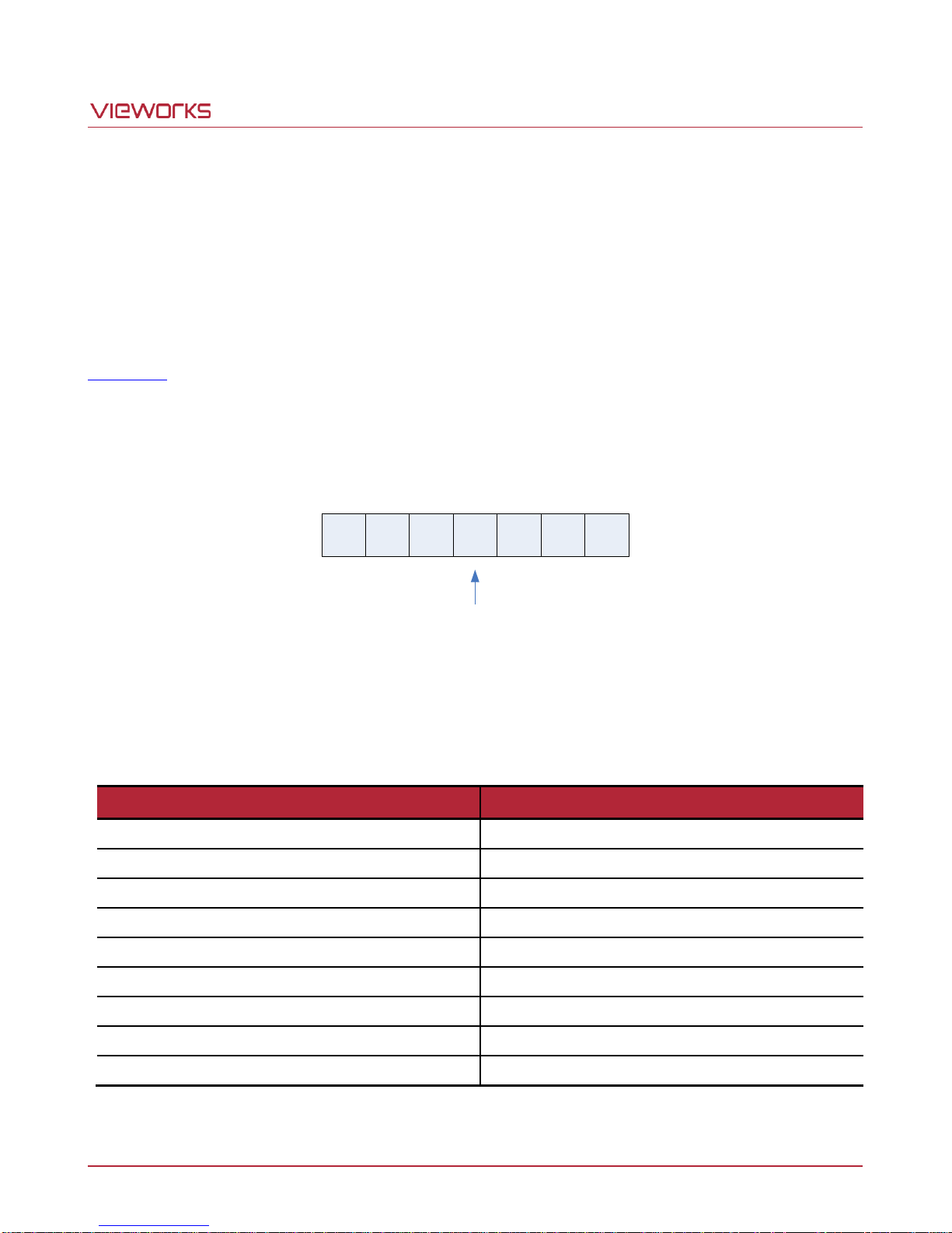
The CCD may have defect pixels which cannot properly respond to the light. VA-29MC2 6 provides a feature to
correct the defect pixels to enhance the quality of output images. Defect pixel information of the CCD used for
each camera is saved in the camera during the manufacturing process in the factory. If you want to add defect
pixel information, it is required to enter coordinate of new defect pixel into the camera. You can determine
whether to use the Defective Pixel Correction feature by using the “sdc” command. For more information, refer to
Appendix A.
8.7.1 Correction Method
Correction value for a defect pixel is calculated based on valid pixel value adjacent in the same line.
Figure 8.19 Location of Defect Pixel to be corrected
If the current pixel is a defect pixel as shown in the above figure, correction value for this pixel is obtained as
shown in the following table depending on whether adjacent pixels are defect pixel or not.
Table 8.3 Calculation of Defect Pixel Correction Value
Page 39 of 78 VW40-158-009
Page 40
VA-29MC2-6
Executing the Flat Field Generator will ignore the current camera settings and will
temporarily change the camera settings to operate under the following default conditions.
When the generation of the Flat Field data is complete, the original camera settings will
be restored.
Readout Mode: Normal
Trigger Mode: Free-Run
Defective Pixel Correction: ON
The target value M is based on the Normal readout mode. If you use different AOI
settings or Channel mode, the level value of an actual image may be different with the
target value.
8.8 Flat Field Correction
The Flat Field Correction feature improves the image uniformity when you acquire a non-uniformity image due to
external conditions. The Flat Field Correction feature can be summarized by the following equation:
IC = {(IR – IB) × M} / (IF – IB)
IC: Level value of corrected image
IR: Level value of original image
IB: Black offset value
M: Target value of image after correction
IF: Level value of Flat Field data
In the actual use conditions, generate a Flat Field data (IF) and enable the Flat Field Correction feature
according to the following procedures.
1. Set the number of frames to be used for generating the Flat Field data by using the “sfi n” command
(number of frames = 2n).
2. Set the target value M to be applied after correction by using the “sfo” command.
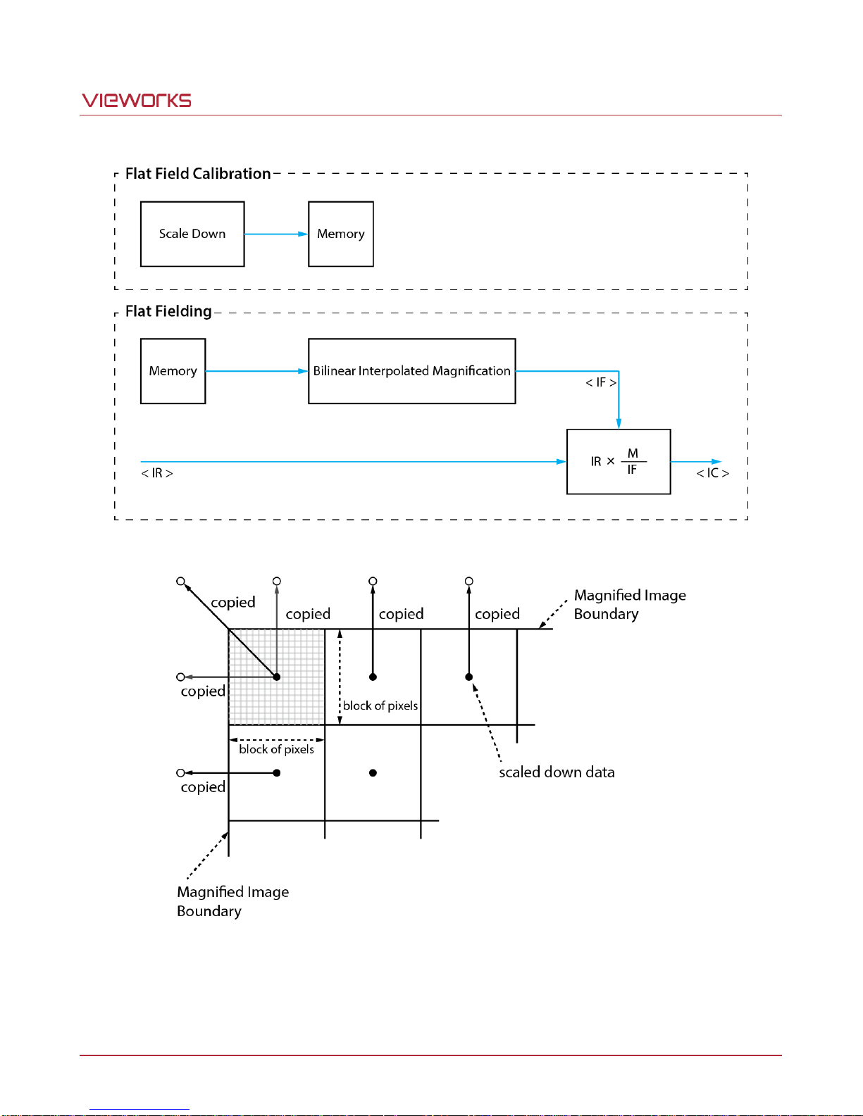
3. Execute the Flat Field Generator by using the “gfd” command. The Flat Field Generator will average series
of frames and scale down to 1/16 pixel to generate the Flat Field data. The Flat Field data will be saved in
the external frame buffer (volatile memory).
4. Enable the Flat Field Correction feature by using the “sfc” command. The Flat Field data will be enlarged via
Bilinear Interpolation as shown in the Figure 8.21.
5. Save the generated Flat Field data in the non-volatile memory by using the “sfd” command for future use.
Page 40 of 78 VW40-158-009
Page 41
VA-29MC2-6
Figure 8.20 Generation and Application of Flat Field Data
Figure 8.21 Bilinear Interpolated Magnification
Page 41 of 78 VW40-158-009
Page 42

VA-29MC2-6
8.9 Temperature Monitor
The camera is equipped with a temperature sensor to monitor the internal temperature. You can check the
temperature of the camera by using the “gct” command.
8.10 Status LED
A Green LED is installed on the back panel of the camera to inform the operation status of the camera.
LED status and corresponding camera status area as follows:
Continuous ON – operates in the Free-Run mode.
Repeat On for 0.5 second, Off for 0.5 second – operates in the Trigger Mode.
Repeat On for 1 second, Off for 1 second – outputs Test Image.
Repeat On for 0.25 second, Off for 0.25 second – operates in the Trigger Mode and outputs Test Image.
Page 42 of 78 VW40-158-009
Page 43
VA-29MC2-6
MSB
LSB
12Bit Output
10Bit Output
8Bit Output
D9 D8 D7 D6 D5 D4 D3 D2 D1 D0
D11 D10 D9 D8 D7 D6 D5 D4 D3 D2 D1 D0
D7 D6 D5 D4 D3 D2 D1 D0
Original
Data
D11 D10 D9 D8 D7 D6 D5 D4 D3 D2 D1 D0D13 D12
8.11 Data Format
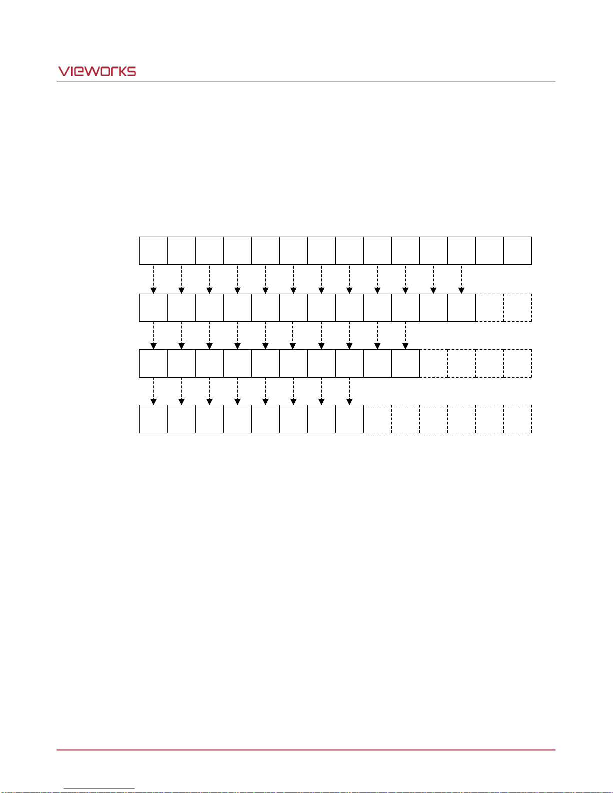
The internal processing of image data is performed in 12 bits. Then, the camera can output the data in 8, 10 or
12 bits. When the camera outputs the image data in 8 bits or 10 bits, the 4 or 2 least significant bits will be
truncated accordingly.
Figure 8.22 Data Format
Page 43 of 78 VW40-158-009
Page 44

VA-29MC2-6
8.12 Test Image
To check whether the camera operates normally or not, it can be set to output test images generated in the
camera, instead of the image data from the CCD. Three types of test images are available; image with different
value in horizontal direction (Test Image 1), image with different value in diagonal direction (Test Image 2), and
moving image with different value in diagonal direction (Test Image 3). The Test Image feature is available in all
operation modes of the camera. You can set the Test Image feature by using the “sti” command.
Figure 8.23 Test Image 1
Page 44 of 78 VW40-158-009
Page 45

VA-29MC2-6
The test image may look different because the region of the test image may vary depending on
the camera’s resolution.
Figure 8.24 Test Image 2
Figure 8.25 Test Image 3
Page 45 of 78 VW40-158-009
Page 46
VA-29MC2-6
8.13 Horizontal Flip
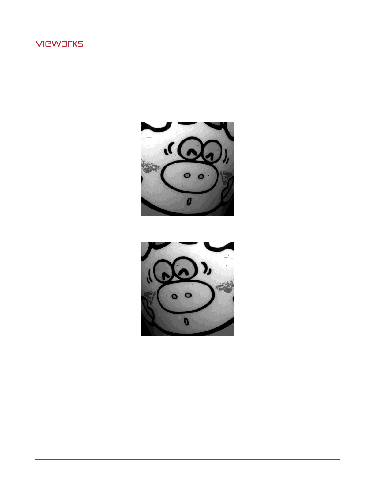
The Horizontal Flip feature lets you flip the image horizontally. This feature is available in all operation modes of
the camera. You can set the Horizontal Flip feature by using the “shf” command.
Figure 8.26 Original Image
Figure 8.27 Horizontal Flipped Image
Page 46 of 78 VW40-158-009
Page 47
VA-29MC2-6
Data Format
Original Value
Inverted Level Value
8 0 255
10
0
1023
12
0
4095
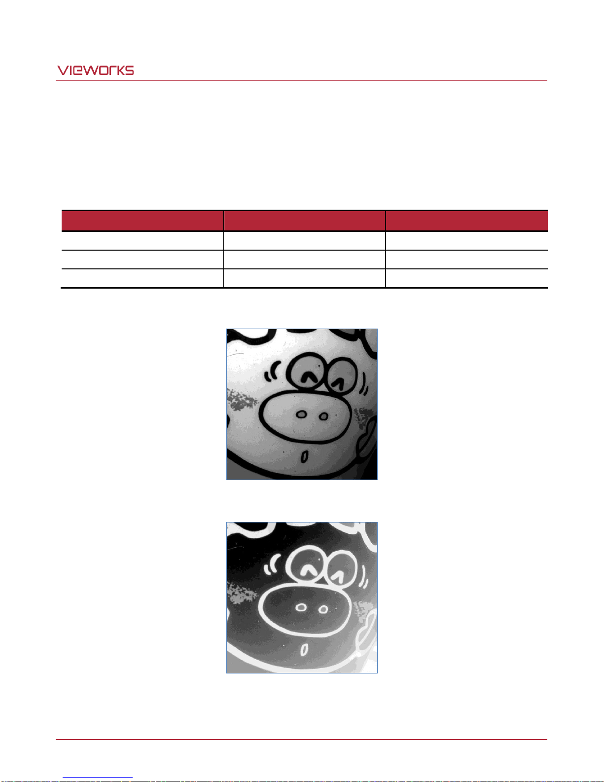
8.14 Image Invert
The Image Invert feature lets you invert the level values of the output image. The inverted level values differ
depending on the Data Format setting even if original values are same. This feature is available in all operation
modes of the camera. You can set the Image Invert feature by using the “sii” command.
Table 8.4 Inverted Level Value depending on the Data Format
Page 47 of 78 VW40-158-009
Figure 8.28 Original Image
Figure 8.29 Inverted Image
Page 48
VA-29MC2-6
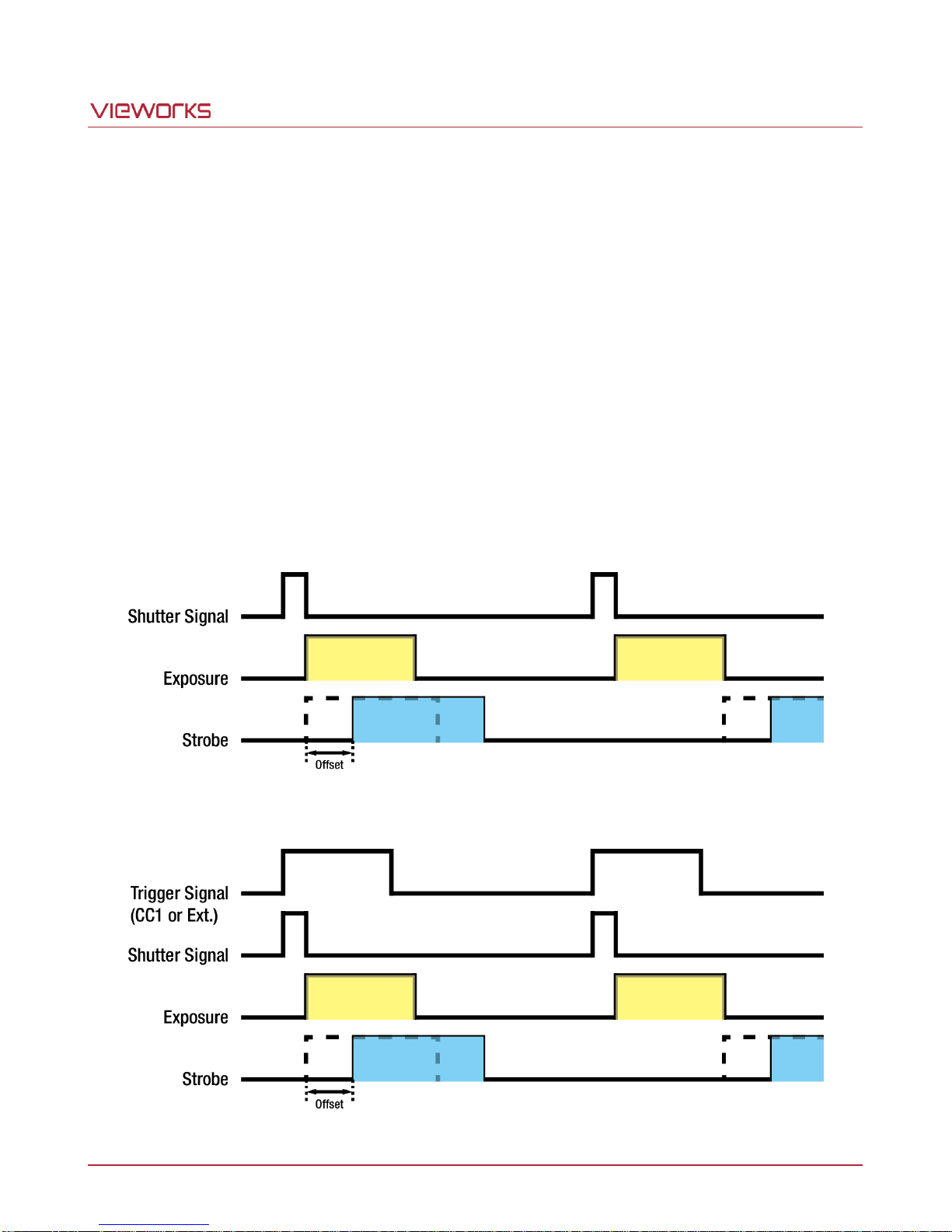
8.15 Strobe
The camera provide a Strobe output signal. The signal goes high when the exposure time for each frame
acquisition begins and goes low when the exposure time ends. This signal can be used as a flash trigger and is
also useful when you are operating a system where either the camera or the object being imaged is movable.
Typically, you do not want the camera to move during exposure. You can monitor the Strobe output signal to
know when exposure is taking place and thus know when to avoid moving the camera.
8.15.1 Strobe Offset
The Strobe Offset value specifies a delay that will be applied between the point where the shutter signal rises
and the point where the Strobe output signal rise. The width of Strobe output signal will be the same as the width
of exposure but only the point where the Strobe output signal rises is adjusted. You can set the Strobe Offset in
microseconds by using the “sso” command.
Figure 8.30 Strobe Signal in the Free-Run mode
Figure 8.31 Strobe Signal in the Trigger mode
Page 48 of 78 VW40-158-009
Page 49

VA-29MC2-6
8.15.2 Strobe Polarity
The Strobe Polarity is used to select Active High or Active Low triggering. You can set the polarity of the strobe
output signal by using the “ssp" command.
8.15.3 Field Upgrade
The camera provides a feature to upgrade Firmware and FPGA logic through the Camera Link interface rather
than disassemble the camera in the field. Refer to Appendix C for more details about how to upgrade.
Page 49 of 78 VW40-158-009
Page 50
VA-29MC2-6
9 Camera Configuration
9.1 Setup Command
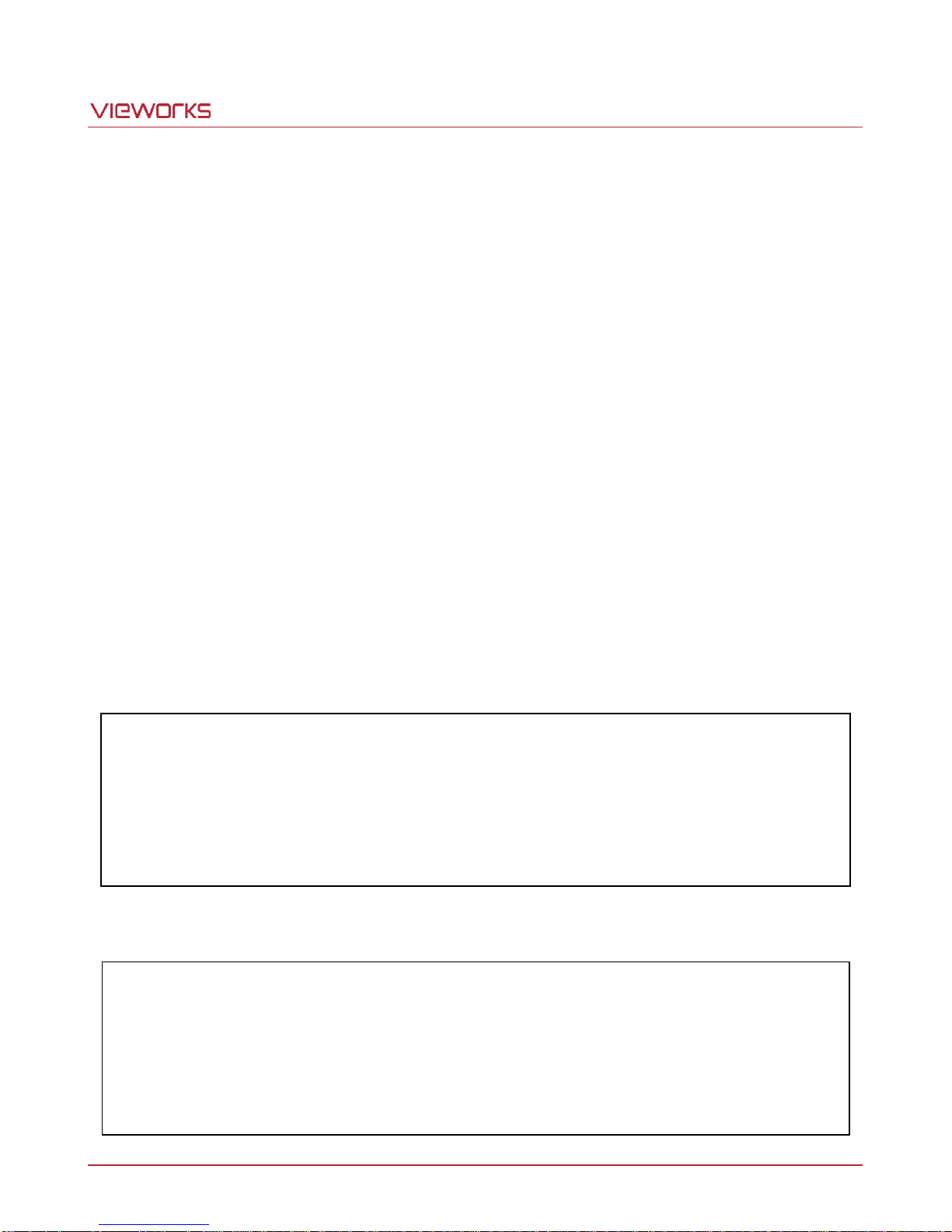
You can configure all camera settings via RS-644 serial interface of the Camera Link. When you want to control
the camera using a terminal or to access directly to the camera at your application, you need to set your network
as follows:
Baud Rate: 19200 bps
Data Bit: 8 bit
Parity Bit: No Parity
Stop Bit: 1 stop bit
Flow Control: None
All camera setting commands are transmitted in the ASCII command type except a command for transmitting a
large file such as firmware download. All camera setting commands are transmitted from the user application
and then the camera returns a response (“OK”, “Error” or information) for a command. When you execute a write
command, the camera returns a response to inform whether the command has been successfully executed.
When you execute a read command, the camera returns an error or information.
Command format:
<command> <parameter1> <parameter2> <cr>
0~2 parameters follow the command.
Response:
If a write command is successfully executed
OK <cr> <lf>
ex) Write Command
In response to a “set 100” command the camera will return (in hex value)
Command : 73 65 74 20 31 30 30 0D
set 100<cr>
Response : 73 65 74 20 31 30 30 0D 0A 4F 4B 0D 0A 3E
set 100<cr><lf> OK<cr><lf> >
Echo result prompt
Page 50 of 78 VW40-158-009
Page 51
VA-29MC2-6
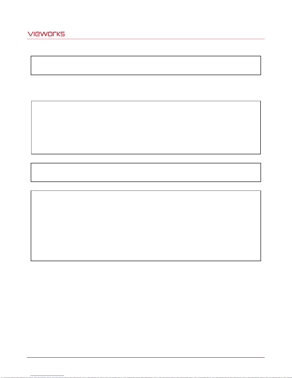
If a read command is successfully executed
<parameter1> <cr> <lf>
ex) Read Command
In response to a “get” command the camera will return (in hex value)
Command : 67 65 74 0D
get <cr>
Response : 67 65 74 0D 0A 31 30 30 0D 0A 3E
get<cr><lf> 100<cr><lf> >
Echo response prompt
If a command is not executed
Error: <Error Code> <cr> <lf>
Prompt:
A prompt always follows after the response. ‘>’ is used as a prompt.
Types of Error Code
0x80000481: value of parameter is not valid
0x80000482: the number of parameter is not matched
0x80000484: command does not exist
0x80000486: no permission to execute
Page 51 of 78 VW40-158-009
Page 52
VA-29MC2-6
9.2 Actual Runtime of Commands
When you execute a command, the actual runtime of the command varies depending on the type of the
command and the operating status of the camera.
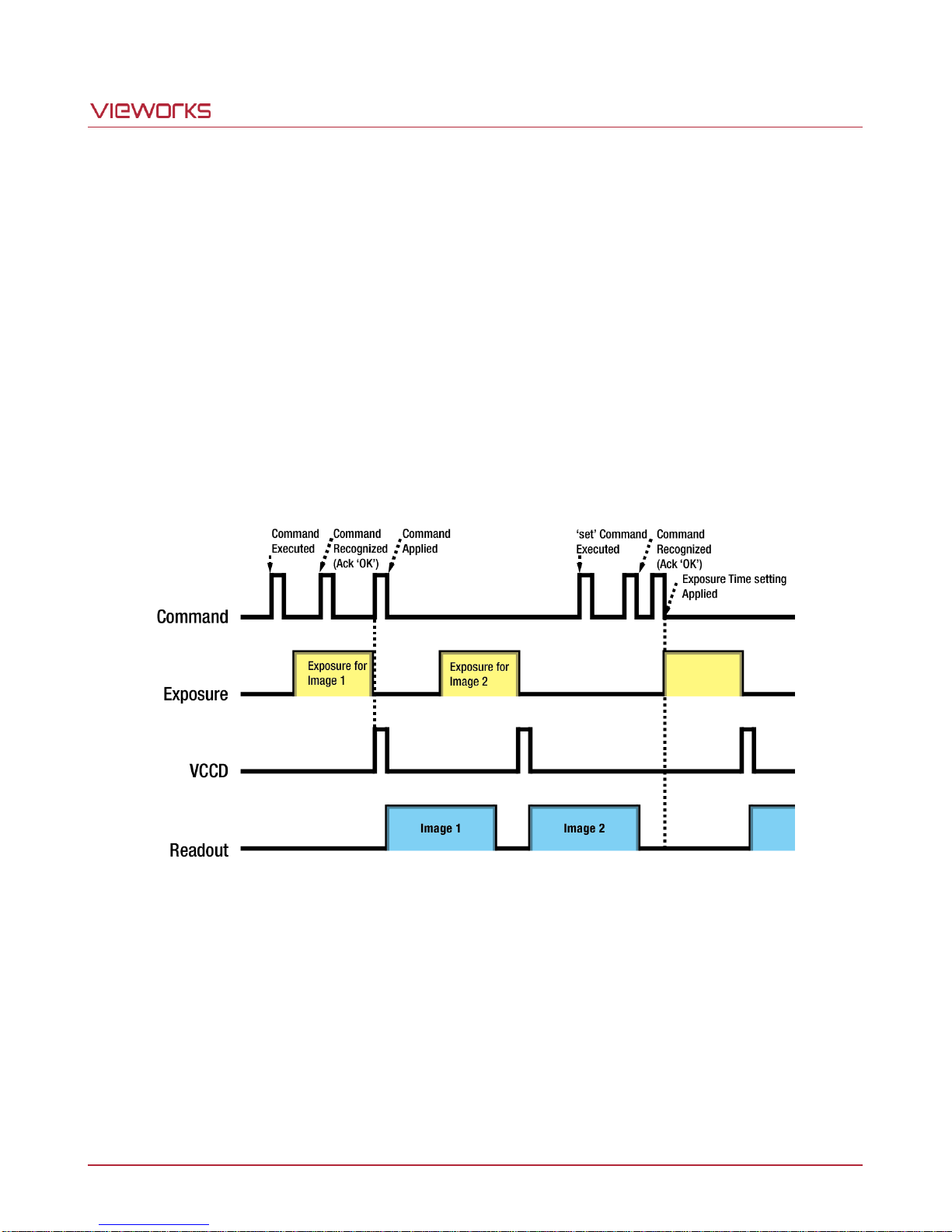
All commands except Set Exposure Time (‘set’) command are applied to change the settings as illustrated
below, on the rising edge of a VCCD signal before starting the readout process. When you execute the ‘set’
command, the exposure time setting will be changed and applied at the starting of the exposure.
If you operate the camera with CC1 or external trigger signals, you must execute commands before applying the
trigger signals in order to synchronize image outputs with the commands.
If you execute a command in the Free-Run mode, you may acquire up to two images that are not affected by the
command execution. This is true because it is hard to verify the current operating status of the camera in the
Free-Run mode.
Page 52 of 78 VW40-158-009
Figure 9.1 Actual Runtime of Commands
Page 53
VA-29MC2-6
Volatile
Memory
(RAM)
Non_volatile
Memory
(ROM)
Work Space
User 1 Space
User 2 Space
Factory Space
9.3 Parameter Storage Space
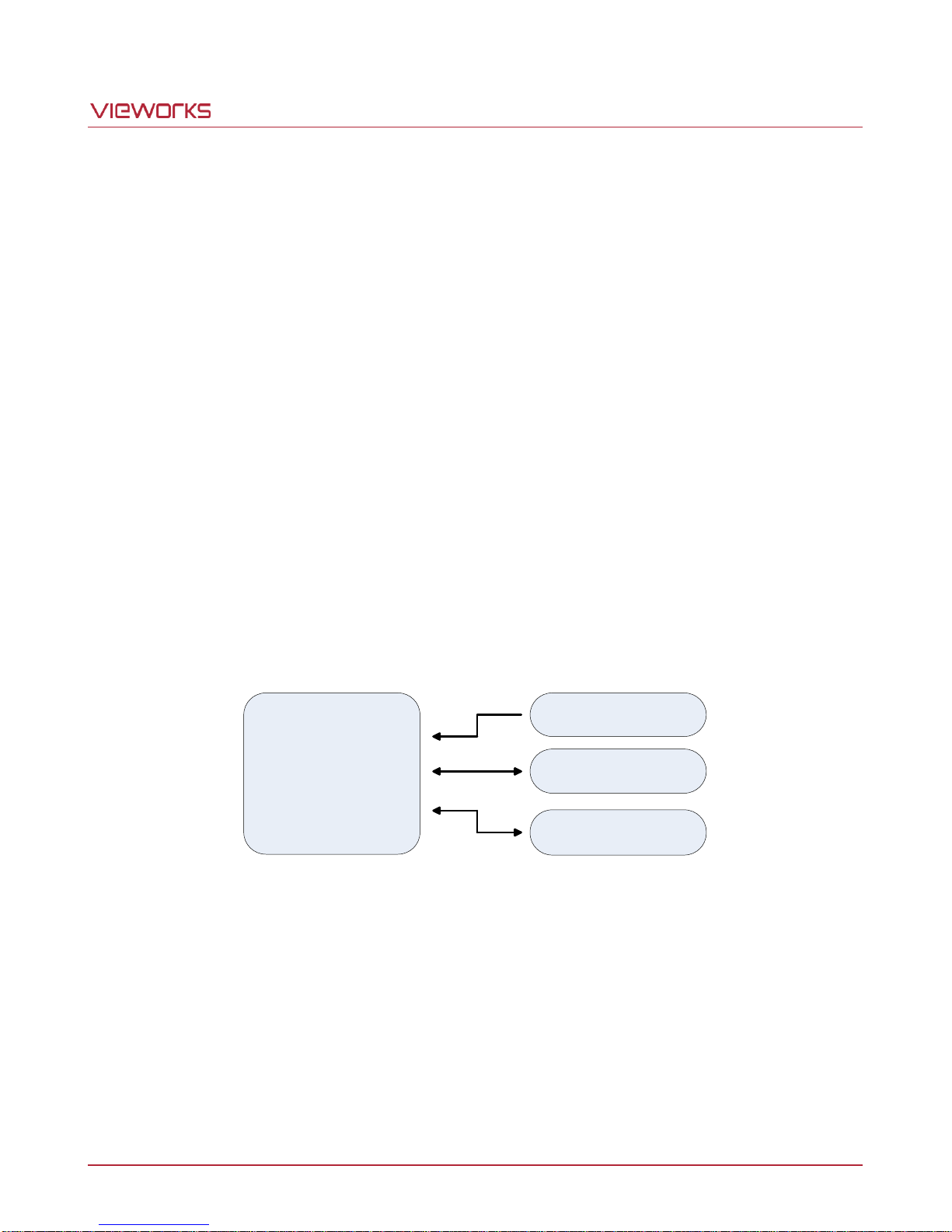
The camera provides three non-volatile spaces for storing parameter settings and one volatile work space. The
work space contains the camera’s current parameter settings. Non-volatile spaces are divided into Factory
Space that contains default values entered during the manufacturing, and two user spaces (User 1 Space and
User 2 Space) that are available for saving parameter settings by users. Read and write operations are allowed
in the user spaces, but only the read operations are allowed in the factory space.
When the camera is powered on or reset, parameter settings stored in one of the storage spaces are loaded into
the work space according to the Config Initialization value. These parameter settings will then determine the
camera’s performance.
The parameter settings in the work space are lost when the camera is powered off or reset. The camera can
save parameter settings from the work space to a user space in the camera’s non-volatile spaces.
The parameter settings stored in the non-volatile spaces are not lost when the camera is powered off or reset.
You can save the current parameter settings to User 1 Space or User 2 Space by using the “sct” command for
future use.
Figure 9.2 Parameter Storage Space
Page 53 of 78 VW40-158-009
Page 54
VA-29MC2-6
Command
Syntax
Value
Returned
Description
Help
h
String
Displays a list of all commands
Set Read-Out Mode
Get Read-Out Mode
srm 0|1|2
grm
OK
0|1|2
0: Normal mode
1: AOI(Area Of Interest) mode
(AOI is set using “sha” and “sva”
commands)
2: Binning(2 or 4) mode
(Binning factor is set using “sbf” command)
Set Horizontal Area
Get Horizontal Area
sha n1 n2
gha
OK
n1 n2
n1: Starting point of horizontal direction
n2: End point of horizontal direction
Set Vertical Area
Get Vertical Area
sva n1 n2
gva
OK
n1 n2
n1: Starting point of vertical direction
n2: End point of vertical direction
Set Binning Factor
Get Binning Factor
sbf 2|4
gbf
OK
2|4
2: 2 by 2 binning
4: 4 by 4 binning
Set Test Image
Get Test Image
sti 0|1|2|3
gti
OK
0|1|2|3
0: Off
1/2: Fixed pattern image
3: Moving pattern image
Set Data Bit
Get Data Bit
sdb 8|10|12
gdb
OK
8|10|12
8: 8 bit output
10: 10 bit output
12: 12 bit output
Set Channel Mode
Get Channel Mode
scm 1|2|4
gcm
OK
1|2|4
1: 1 Tap output
2: 2 Tap output
4: 4 Tap output
Set Pixel clock Selection
Get Pixel clock Selection
sps 0|1
gps
OK
0|1
0: Normal Speed (80 ㎒)
1: High Speed (52 ㎒)
Set LUT Select
Get LUT Select
sls 0|1|2
gls
OK
0|1|2
0: Off
1: LUT1
2: LUT2
Set Defect Correction
Get Defect Correction
sdc 0|1
gdc
OK
0|1
0: Off
1: Active of Defect Correction
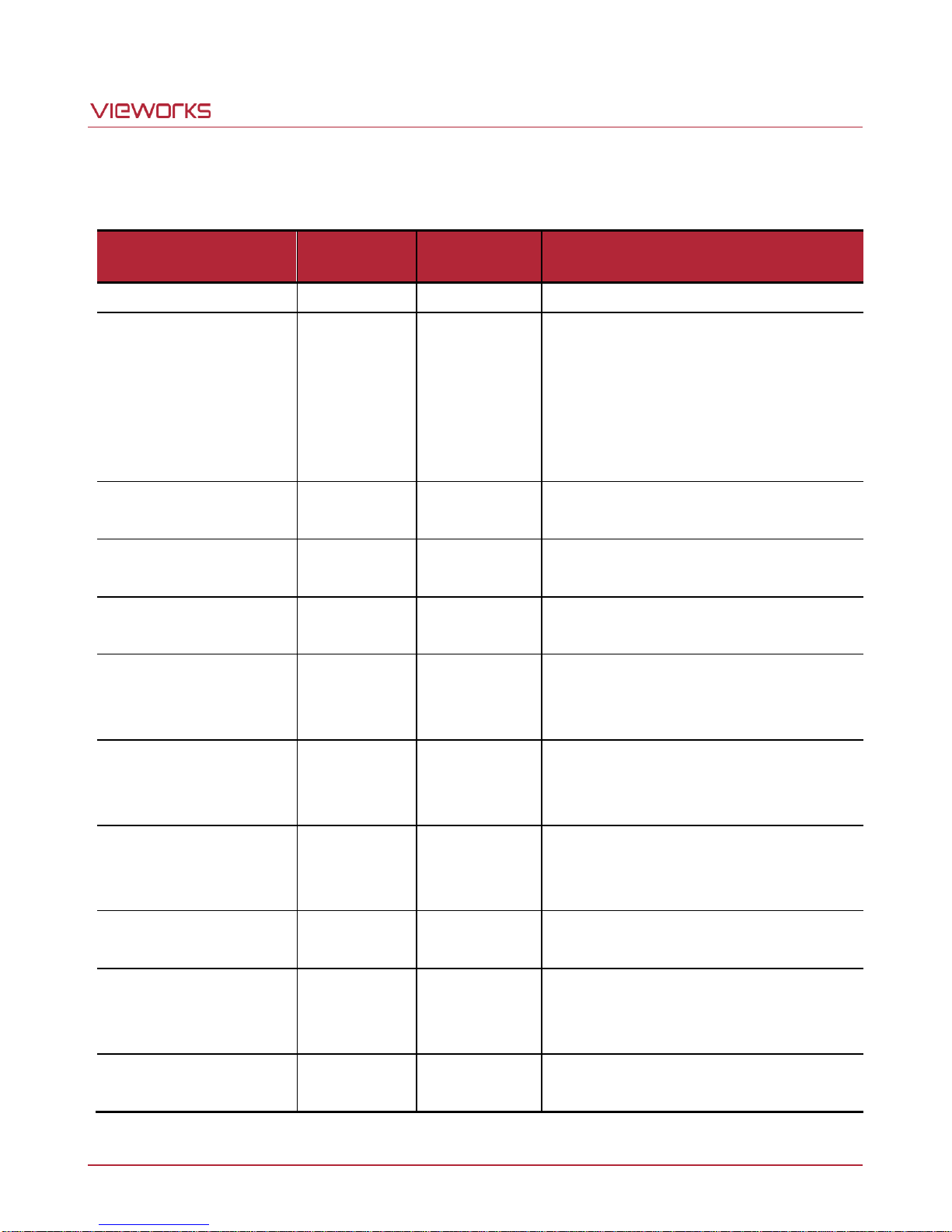
9.4 Command List
Page 54 of 78 VW40-158-009
Table 9.1 Command List #1
Page 55
VA-29MC2-6
Command
Syntax
Value
Returned
Description
Set Image Invert
Get Image Invert
sii 0|1
gii
OK
0|1
0: Off
1: Active of Image Invert
Set Horizontal Flip
Get Horizontal Flip
shf 0|1
ghf
OK
0|1
0: Off
1: Active of Horizontal Flip
Set Trigger Mode
Get Trigger Mode
stm 0|1|2|3|4
gtm
OK
0|1|2|3|4
0: Free-Run mode
1: Standard mode
2: Fast mode
3: Double mode
4: Overlap mode
Set Exposure Source
Get Exposure Source
ses 0|1
ges
OK
1|2
0: Program Exposure(by camera)
1: Pulse Width(by trigger input signal)
Set Trigger Source
Get Trigger Source
sts 1|2
gts
OK
1|2
1: CC1 port input(Camera Link)
2: External input(External control port)
Set Trigger Polarity
Get Trigger Polarity
stp 0|1
gtp
OK
0|1
0: Active low
1: Active high
Set Exposure Time
Get Exposure Time
set n
get
OK
n
n: Exposure Time in ㎲
(Setting range: 1 ~ 60,000,000 ㎲)
Set Strobe Offset
Get Strobe Offset
sso n
gso
OK
n
n: Strobe Offset time in ㎲
(Setting range: 0 ~ 10,000 ㎲)
Set Strobe Polarity
Get Strobe Polarity
ssp 0|1
gsp
OK
0|1
0: Active low
1: Active high
Set Analog Gain
Get Analog Gain
sag n
gag
OK n n: Analog Gain parameter
(Setting range: 0 ~ 899)
Set Gain Offset
Get Gain Offset
sgo 2|3|4 n
ggo 2|3|4
OK
n
2: AFE channel for the right top of image
3: AFE channel for the left bottom of image
4: AFE channel for the right bottom of image
n: Analog Gain Offset parameter
(Setting range: -20 ~ +20)
Auto Gain Offset
ago
OK
Auto-Generation Gain Offset
Set Analog Offset
Get Analog Offset
sao n
gao
OK n n: Analog Offset parameter
(Setting range: 0 ~ 255)
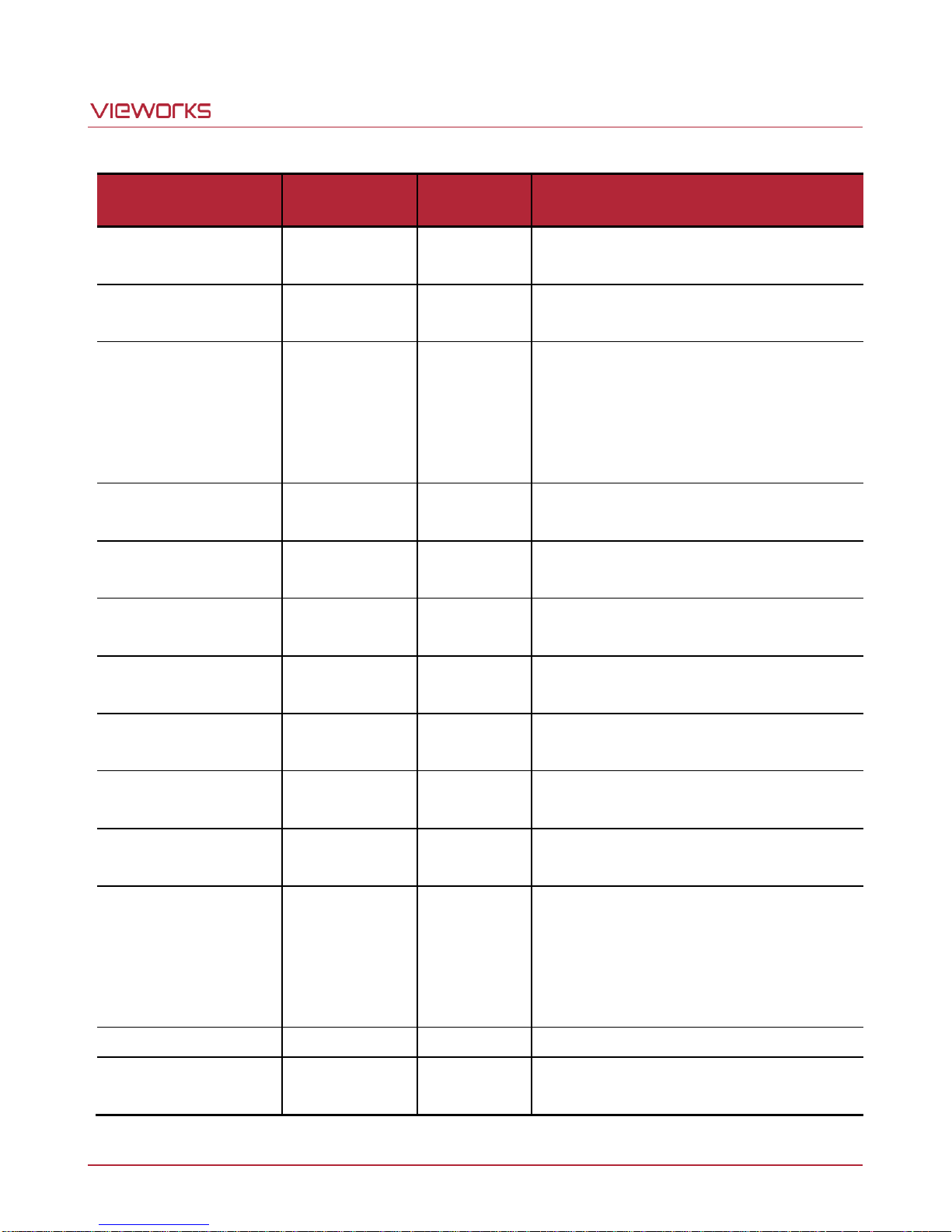
Page 55 of 78 VW40-158-009
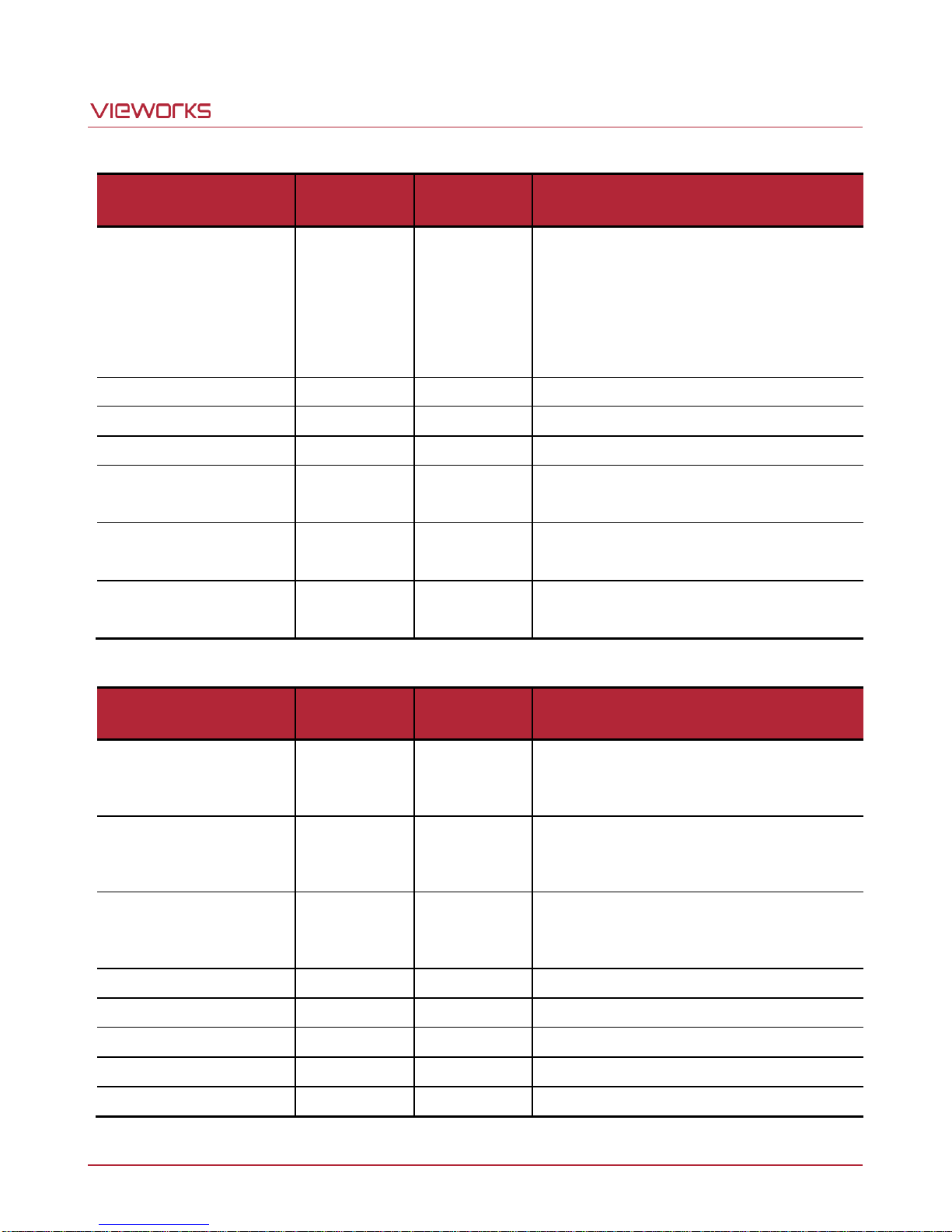
Table 9.2 Command List #2
Page 56
VA-29MC2-6
Command
Syntax
Value
Returned
Description
Set Offset Offset
Get Offset Offset
soo 1|2|3|4 n
goo 1|2|3|4
OK
n
1: AFE channel for the left top of image
2: AFE channel for the right top of image
3: AFE channel for the left bottom of image
4: AFE channel for the right bottom of image
n: Analog Offset Offset parameter
(Setting range: 0~12)
Generate Flat Field Data
gfd
OK
Operate Flat Field generator
Save Flat Field Data
sfd
OK
Save Flat Field data
Load Flat Field Data
lfd
OK
Load Flat Field data
Set Flat Field Iteration
Get Flat Field Iteration
sfi n
gfi
OK n n: (2 ^ n) image acquisitions
(Setting range: 0 ~ 4)
Set Flat Field Offset
Get Flat Field Offset
sfo n
gfo
OK n n: Flat Field target level
(Setting range: 0 ~ 4095)
Set Flat Field Correction
Get Flat Field Correction
sfc 0|1
gfc
OK
0|1
0: Off
1: Active of Flat-Field Correction
Command
Syntax
Value
Returned
Description
Load Config From
lcf 0|1|2
OK
0: Load from Factory Setting
1: Load from User 1 Setting
2: Load from User 2 Setting
Save Config To
sct 1|2
OK
0: Save to User 0 Setting(not available)
1: Save to User 1 Setting
2: Save to User 2 Setting
Set Config Initialization
Get Config Initialization
sci 0|1|2
gci
OK
0|1|2
0: Load from Factory Setting when initializing
1: Load from User 1 Setting when initializing
2: Load from User 2 Setting when initializing
Get MCU Version
gmv
String
Display MCU version
Get Model Number
gmn
String
Display Model Number
Get FPGA Version
gfv
String
Display FPGA version
Get Serial Number
gsn piece
String
Display Serial Number
Get Current Temperature
gct
String
Display Temperature value
Page 56 of 78 VW40-158-009
Table 9.3 Command List #3
Table 9.4 Command List #4
Page 57
VA-29MC2-6
10 Configurator GUI
Configurator, a sample application, is provided to control the VA-29MC2-6 camera. Configurator provides easyto-use Graphic User Interface (GUI) that allows users to view and change the camera’s parameter settings
mentioned in the previous chapters.
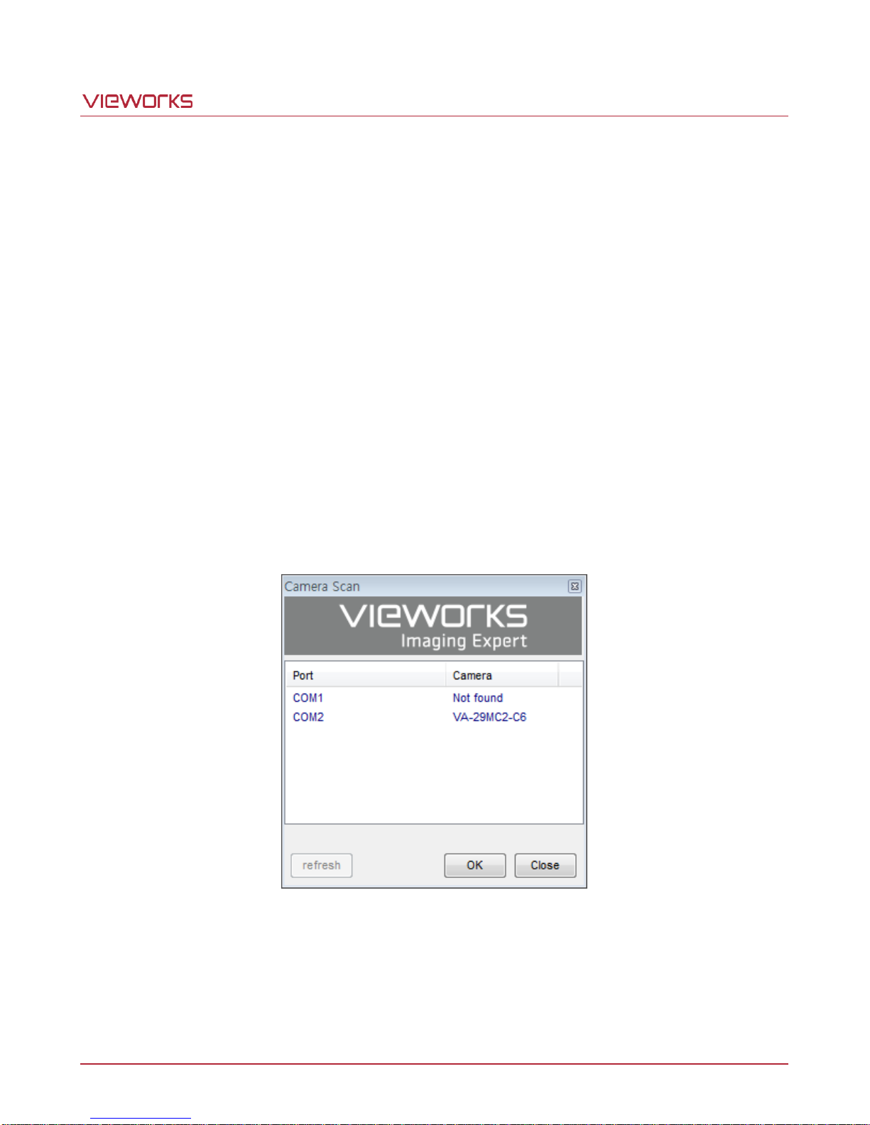
10.1 Camera Scan
When you execute the Configurator.exe file while the camera is powered on, the Camera Scan window appears
as shown in the figure below. At this time, the Configurator checks serial port of your computer and DLL provided
by the Camera Link to scan whether a camera is connected. If the Configurator finds a connected camera, it
displays the model name of the camera on the Camera Scan window. If the camera is not displayed on the
window, check the cable connections and power of the camera, and then press the refresh button.
Double-clicking the model name of the camera displayed on the window will launch the Configurator and display
the current parameter settings of the camera connected.
Figure 10.1 Configurator Loading Window
Page 57 of 78 VW40-158-009
Page 58
VA-29MC2-6
10.2 Menu
10.2.1 File
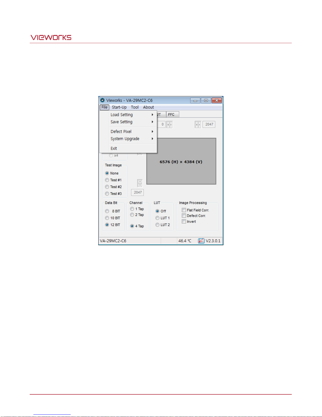
Figure 10.2 File Menu
Load Setting: Loads the camera setting values from the camera memory (Factory, User1,
or User2) or user’s computer (From File).
Save Setting: Saves the current camera setting values to the camera memory (User1 or
User2) or user’s computer (To File).
Defect Pixel: Downloads defect information to the camera (Download to Camera) or
uploads defect information stored in the camera to the user’s computer
(Upload to PC).
System Upgrade: Upgrades MCU or FPGA logic.
Exit: Exits the Configurator.
Page 58 of 78 VW40-158-009
Page 59
VA-29MC2-6
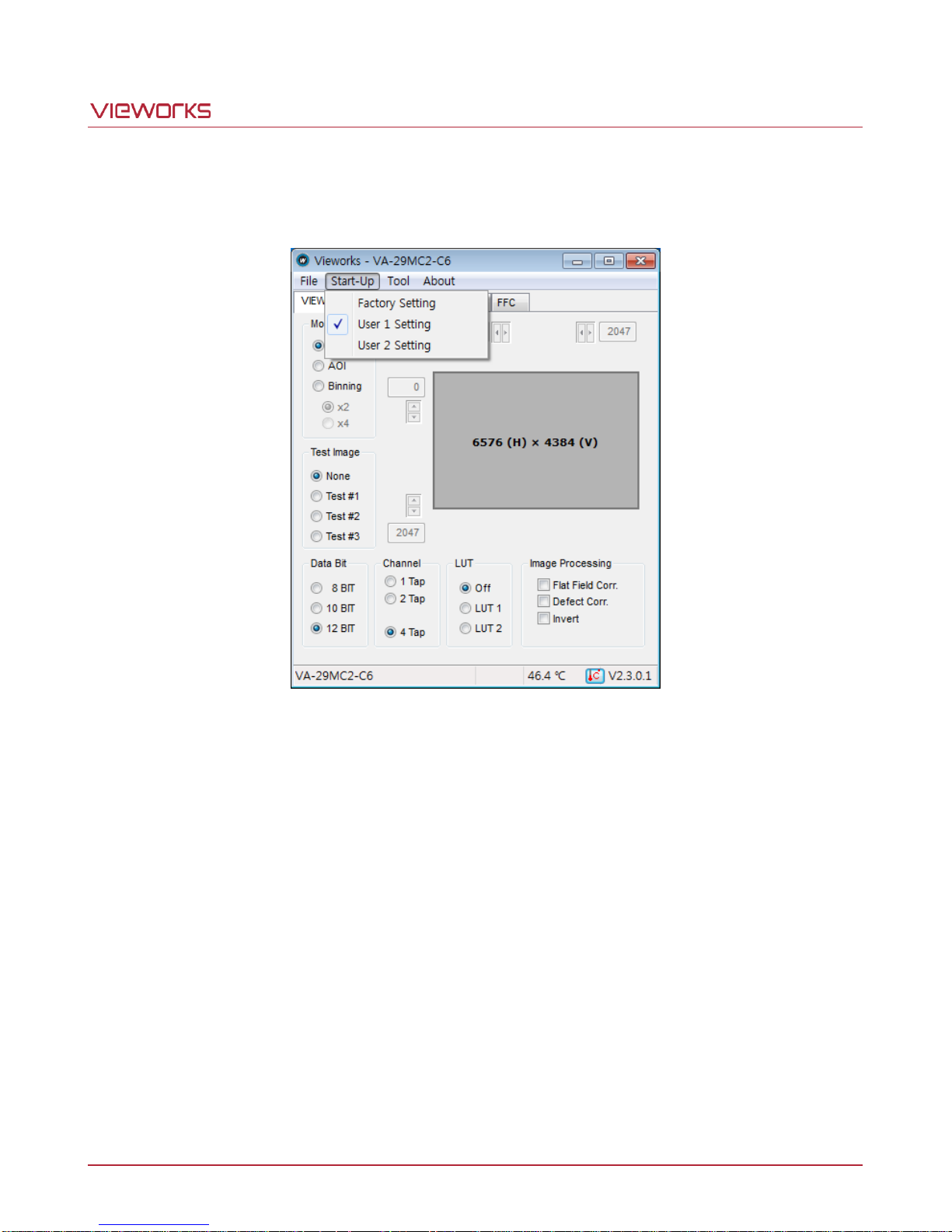
10.2.2 Start-Up
You can select the camera setting values to load when the camera is powered on.
Figure 10.3 Start-Up Menu
Factory Setting: Loads the camera setting values from Factory Space.
User 1 Setting: Loads the camera setting values from User1 Space.
User 2 Setting: Loads the camera setting values from User2 Space.
Page 59 of 78 VW40-158-009
Page 60
VA-29MC2-6
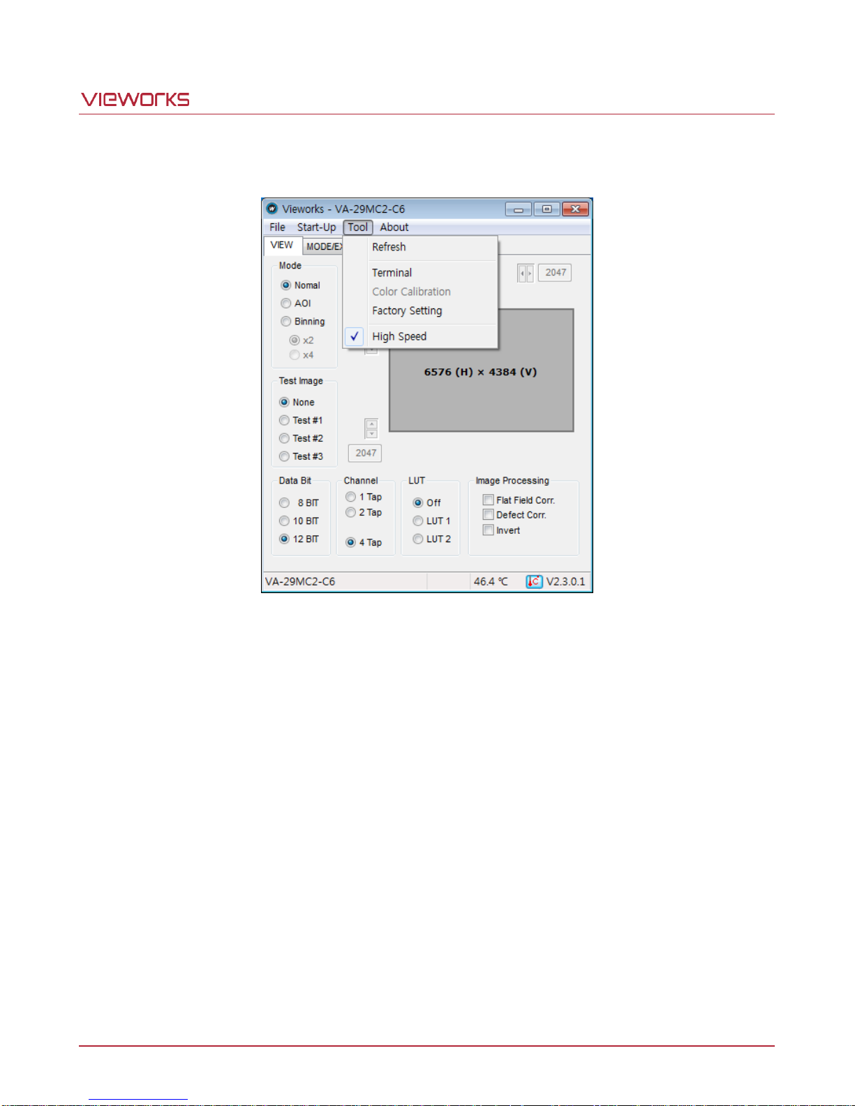
10.2.3 Tool
Figure 10.4 Tool Menu
Refresh: Loads and displays the current camera setting values on the Configurator.
Terminal: Displays a user command in the Terminal window under the GUI.
To hide the Terminal window, uncheck Terminal by clicking again.
Color calibration: Not supported in the VA-29MC2-6.
Factory Setting: Not supported for users.
High Speed: Select the High Speed to operate the camera in the High Speed mode.
To operate the camera in the Normal Speed mode, deselect the High Speed.
Page 60 of 78 VW40-158-009
Page 61
VA-29MC2-6
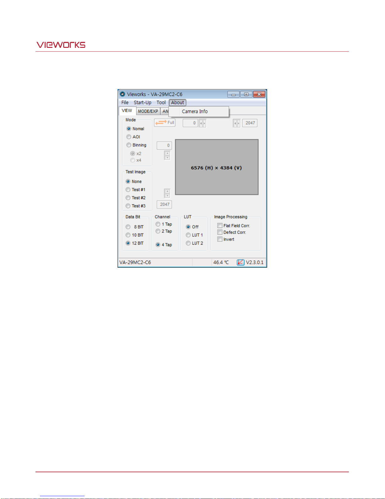
10.2.4 About
Figure 10.5 About Menu
Camera Info: Displays camera information (model name, serial number, version, etc.).
Page 61 of 78 VW40-158-009
Page 62
VA-29MC2-6
10.3 Tab
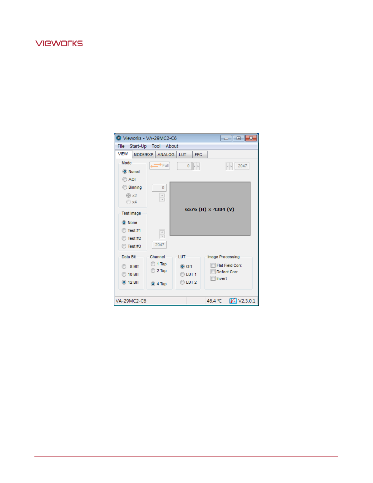
10.3.1 VIEW Tab
The VIEW tab allows you to set the camera’s readout mode, test image mode, data bit, channel, LUT, image
processing, etc.
Mode: Selects the readout mode. If AOI is selected, the AOI setting area will be
activated. You can set the AOI by entering desired values. If Binning is
selected, ×2 and ×4 option buttons will be activated.
Test Image: Selects whether to apply test image and a type of test image.
Data Bit: Selects bit depth of data output.
Channel: Selects a channel mode.
LUT: Selects whether to apply LUT and a type of LUT.
Imaging Processing: Sets Flat Field Correction, Defect Correction or Image Invert features On or
Off.
Page 62 of 78 VW40-158-009
Figure 10.6 VIEW Tab
Page 63
VA-29MC2-6
10.3.2 MODE/EXP Tab
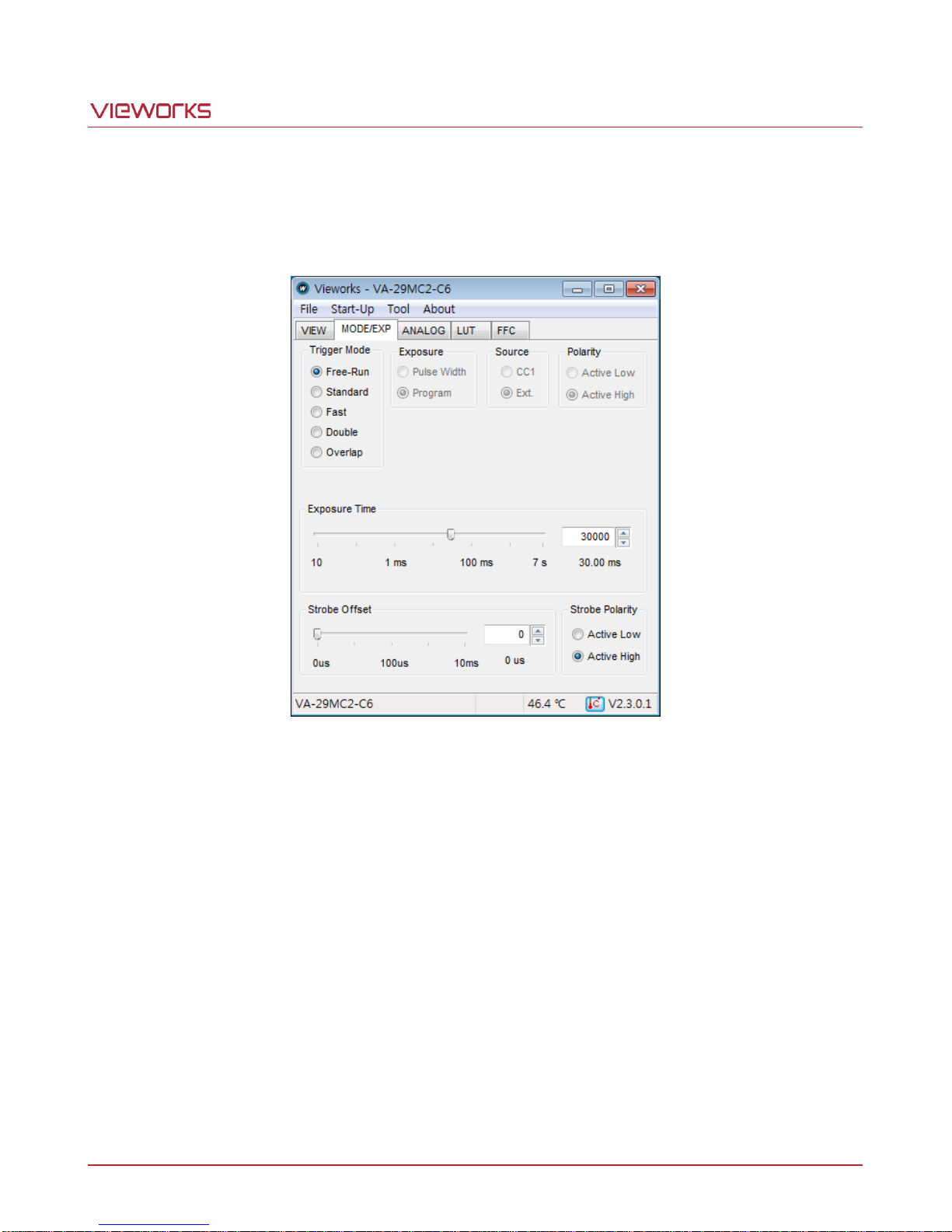
The MODE/EXP Tab allows you to configure the camera’s trigger mode, exposure time and strobe. All scroll bars
in the GUI are controllable with the mouse wheel scroll.
Figure 10.7 MODE/EXP Tab
Trigger Mode: Selects a trigger mode. Once you select a trigger mode, selections related
with the trigger mode will be activated.
Exposure: Selects an exposure mode.
Source: Selects a source signal for exposure triggering.
Polarity: Selects a polarity of trigger signals.
Exposure Time: Sets exposure time when the Trigger Mode is set to Free-Run or
when Exposure is set to Program.
Strobe Offset: Sets a delay for the Strobe output signal.
Strobe Polarity: Selects a polarity of the Strobe output signal.
Page 63 of 78 VW40-158-009
Page 64
VA-29MC2-6
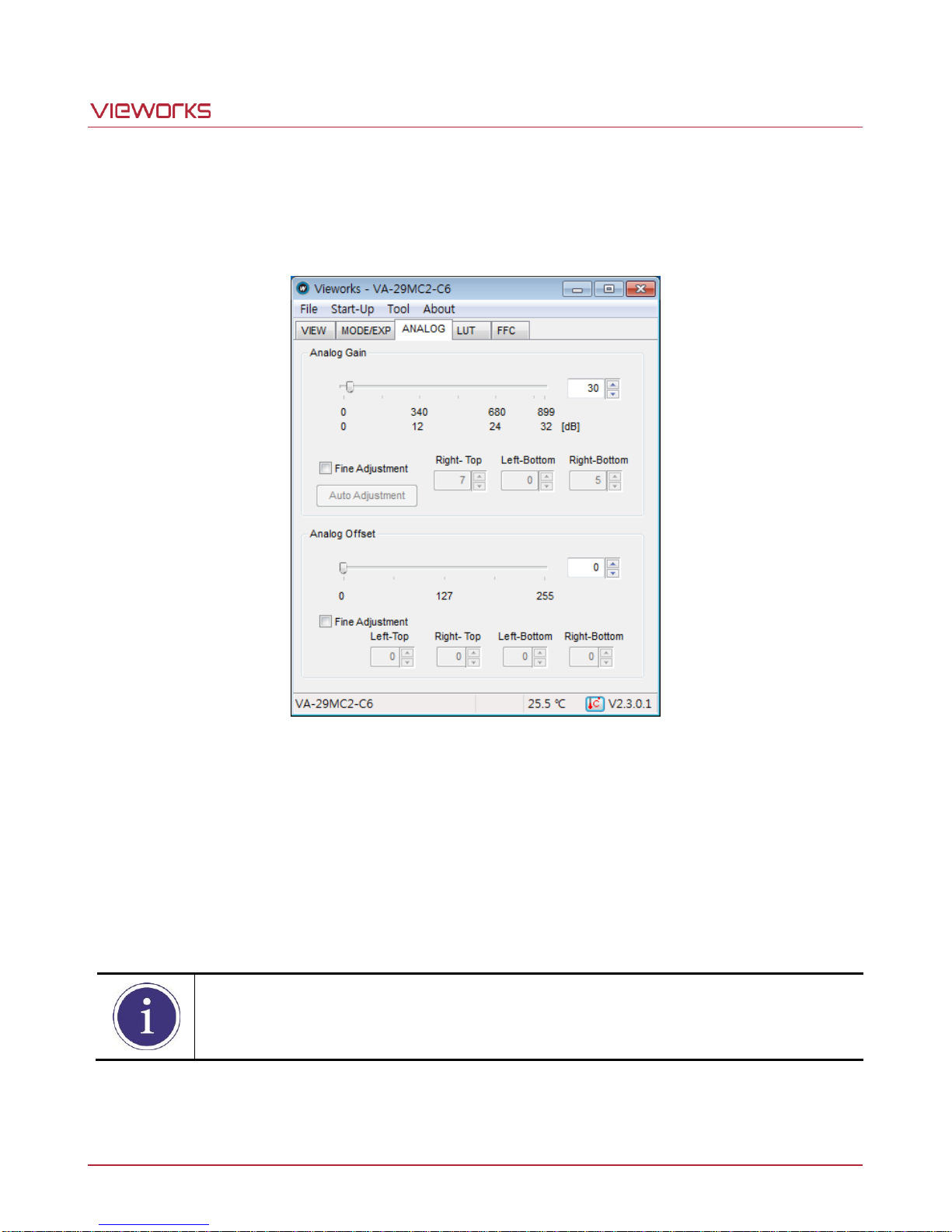
After clicking the Auto Adjustment button, at least one or more images must be acquired by
the camera.
10.3.3 ANALOG Tab
The ANALOG tab allows you to adjust the camera’s gain and offset settings. All scroll bars in the GUI are
controllable with the mouse wheel scroll.
Figure 10.8 ANALOG Tab
Analog Gain: Sets a gain value for each channel. The Auto Adjustment button will be
activated after checking the Fine Adjustment checkbox. Clicking the Auto
Adjustment button will compensate the Tap differences automatically.
With the Fine Adjustment checkbox selected, you can adjust gain values for
each Right-Top, Left-Bottom and Right-Bottom based on the gain value for
the Left-Top.
Analog Offset: Sets a black offset value for each channel.
Page 64 of 78 VW40-158-009
Page 65
VA-29MC2-6
10.3.4 LUT Tab
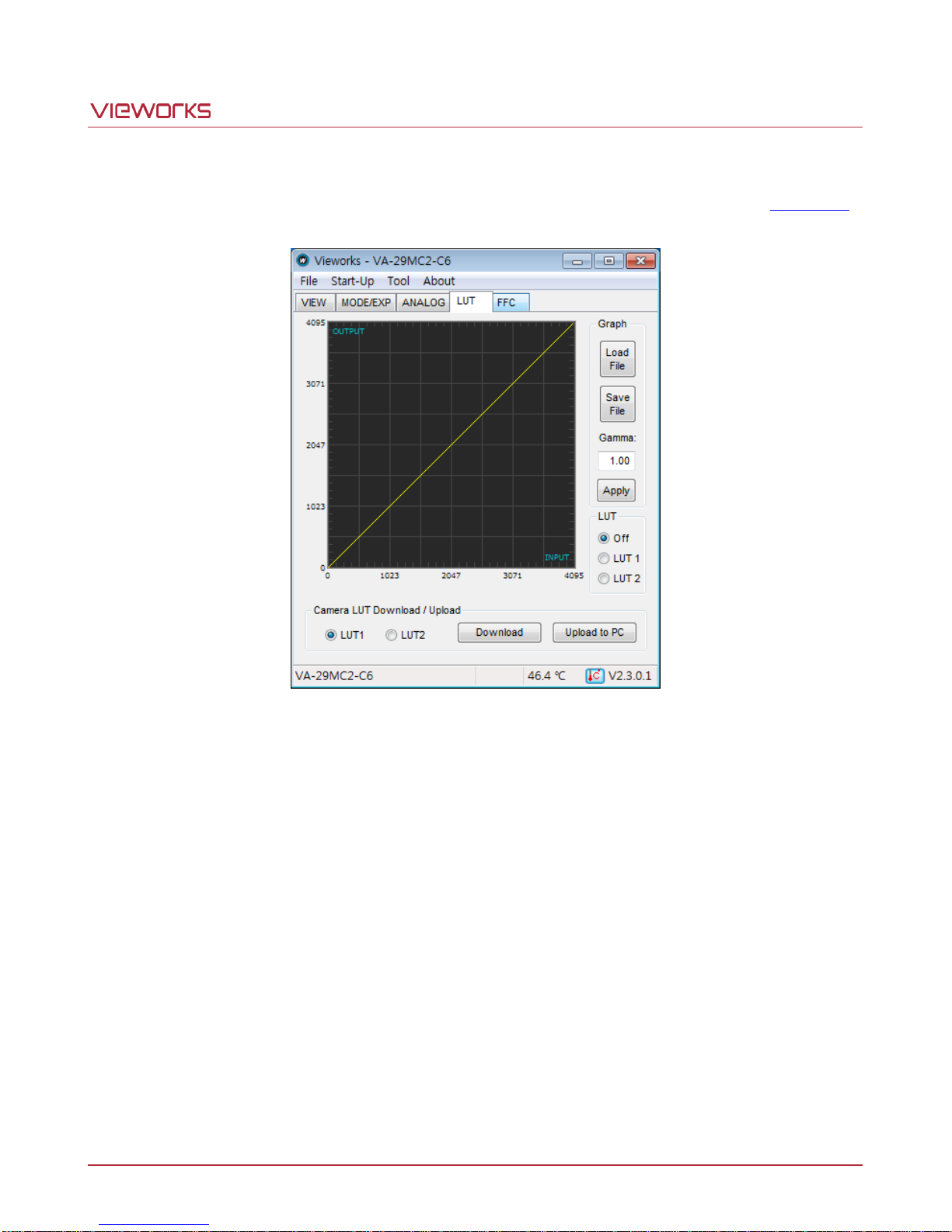
The LUT tab allows you to download LUT data. For more information about LUT download, refer to Appendix B.
Figure 10.9 LUT Tab
Graph: Loads LUT data from user’s computer or sets a Gamma value to be
applied while using a Gamma curve.
Camera LUT Download / Upload: Downloads LUT data stored in user’s computer to the camera
(Download) or uploads LUT data stored in the camera to user’s
computer (Upload to PC).
Page 65 of 78 VW40-158-009
Page 66
VA-29MC2-6
10.3.5 FFC Tab
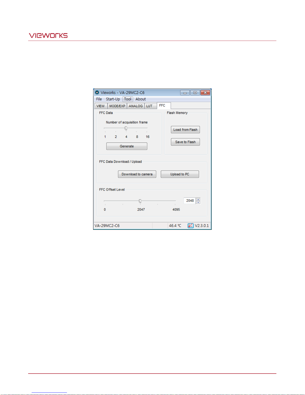
The FFC tab allows you to set the Flat Field Correction feature. All scroll bars in the GUI are controllable with the
mouse wheel scroll.
Figure 10.10 FFC Tab
FFC Data: Sets the number of frames to be used for generating Flat Field Correction
data. Clicking the Generate button will generate Flat Field data.
Flash Memory: Saves the generated FFC data in the Flash for future use (Save to Flash) or
loads the FFC data stored in the Flash (Load from Flash).
FFC Data Download / Upload: Downloads the FFC data stored in user’s computer to the camera (Download
to camera) or uploads FFC data stored in the camera to user’s computer
(Upload to PC).
FFC Offset Level: Sets the target value to be applied after correction.
Page 66 of 78 VW40-158-009
Page 67

VA-29MC2-6
11 Troubleshooting
When you have a problem with a Vieworks camera, please check the following:
If no image is displayed on your computer,
Ensure that all cable connections are secure.
Ensure that the power supply is properly connected.
Ensure that trigger signals are applied correctly when you operate the camera with trigger signals.
If images are not clear,
Ensure the camera lens or glass is clean.
Check the lens aperture is adjusted properly.
If images are dark,
Ensure the camera lens is not blocked.
Check the exposure time is set properly.
Check the aperture is opened properly.
If you identify abnormal operation or overheating sign,
Ensure the power supply is properly connected.
Stop using the camera when you notice smoke or abnormal overheating.
If you have a problem using the Trigger Mode,
Ensure that parameter settings on your Frame Grabber are configured correctly when you operate the
camera with CC1 trigger signals.
Ensure that cable connections are secure when you operate the camera with external trigger signals.
If you notice the difference between left and right image,
Check whether gain settings for left and right are different.
Check whether black offset settings for left and right are different.
If there is a communication failure between the camera and user’s computer,
Ensure Camera Link cables are connected properly.
Ensure that you have configured a Frame Grabber in user’s computer correctly and the camera is
connected properly to the Frame Grabber.
Page 67 of 78 VW40-158-009
Page 68
VA-29MC2-6
Appendix A Defective Pixel Map Download
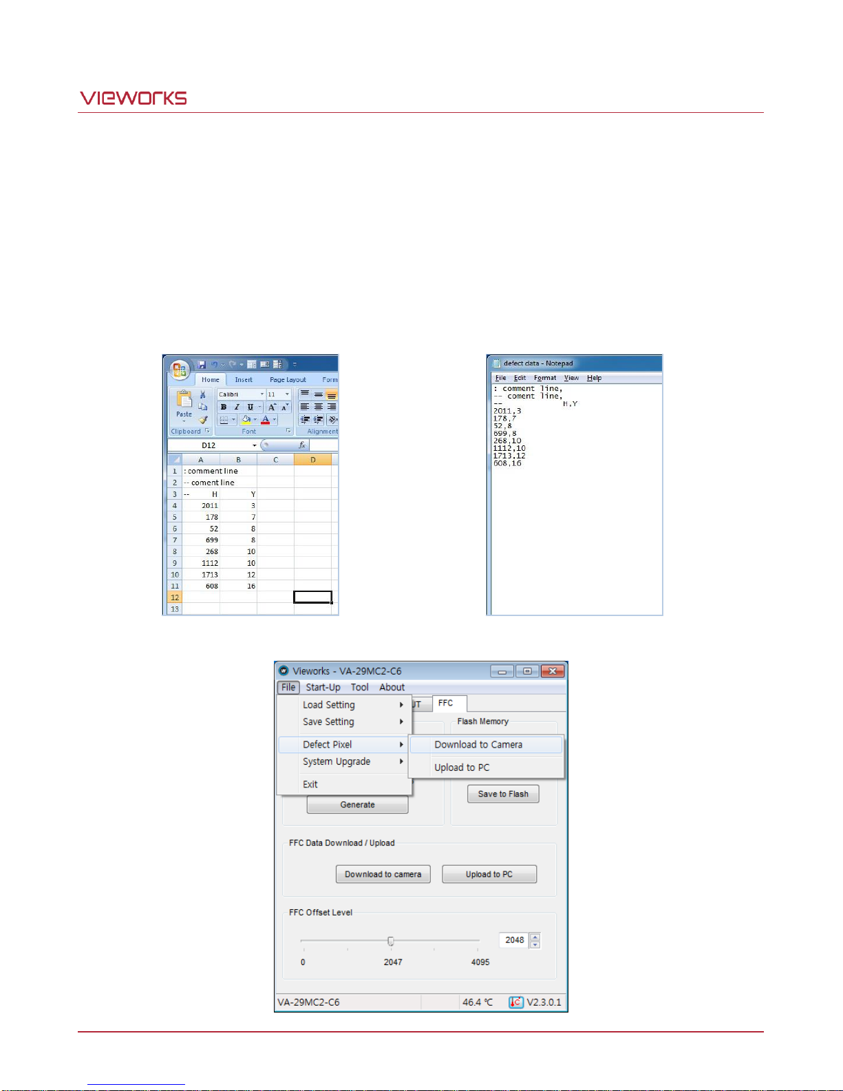
1. Create a Defect Pixel Map in Microsoft Excel format as shown in the left picture below and save as a CSV
file (*.csv). The picture in the right shows the created Excel file opened with Notepad. The following rules
need to be applied when creating the file.
Lines beginning with ‘:’ or ‘—‘ are treated as notes.
You must enter the horizontal value first and then the vertical value for coordinates of each defect pixel.
Coordinate values for each defect pixel can be placed in any order.
2. Select File > Defect Pixel > Download to Camera in the Configurator.
Page 68 of 78 VW40-158-009
Page 69
VA-29MC2-6
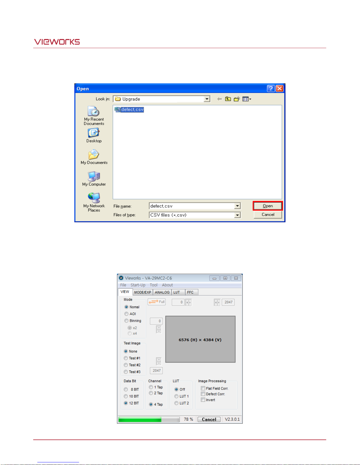
3. Search and select the created file and click Open.
4. The Configurator starts downloading Defect Pixel Map to the camera and downloading status is displayed
at the bottom of the window.
Page 69 of 78 VW40-158-009
Page 70
VA-29MC2-6
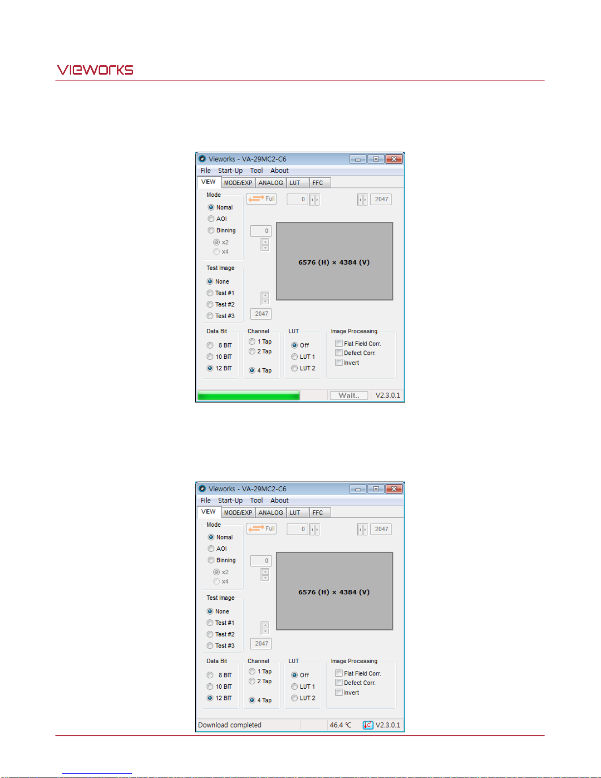
5. Once the download is complete, the saving process will begin. During the saving process, make sure not to
disconnect the power cord.
6. Once all the processes are complete, the Download completed message will appear at the bottom of the
window.
Page 70 of 78 VW40-158-009
Page 71
VA-29MC2-6
Appendix B LUT Download
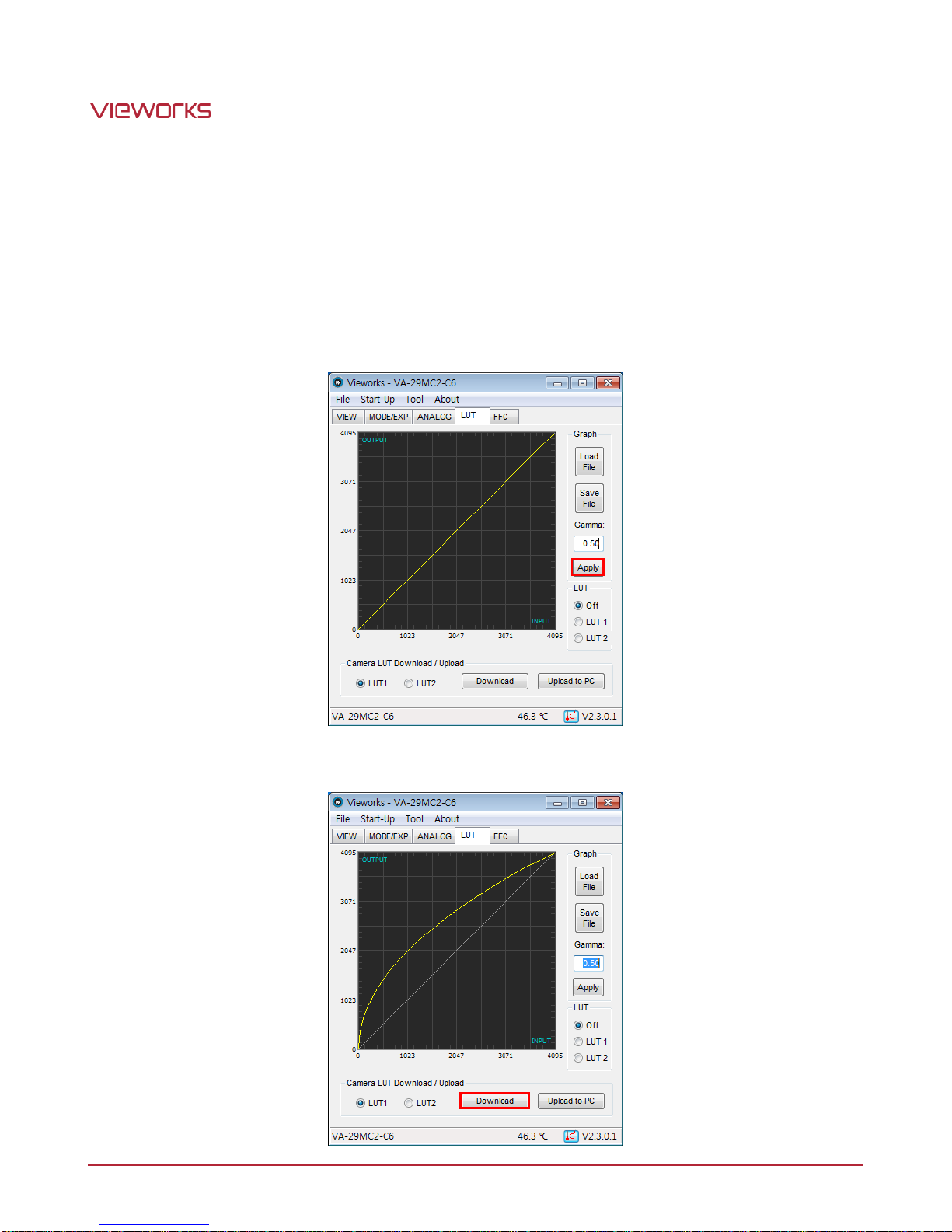
There are two ways to apply LUT data; by adjusting the gamma value on the gamma graph provided in the
Configurator and then downloading the data or by opening a CSV file (*.csv file) and then downloading the data.
B.1 Gamma Graph Download
1. Set a desired gamma value in the LUT tab and click Apply.
2. Select LUT1 or LUT2 as a location to store the data and click Download.
Page 71 of 78 VW40-158-009
Page 72
VA-29MC2-6
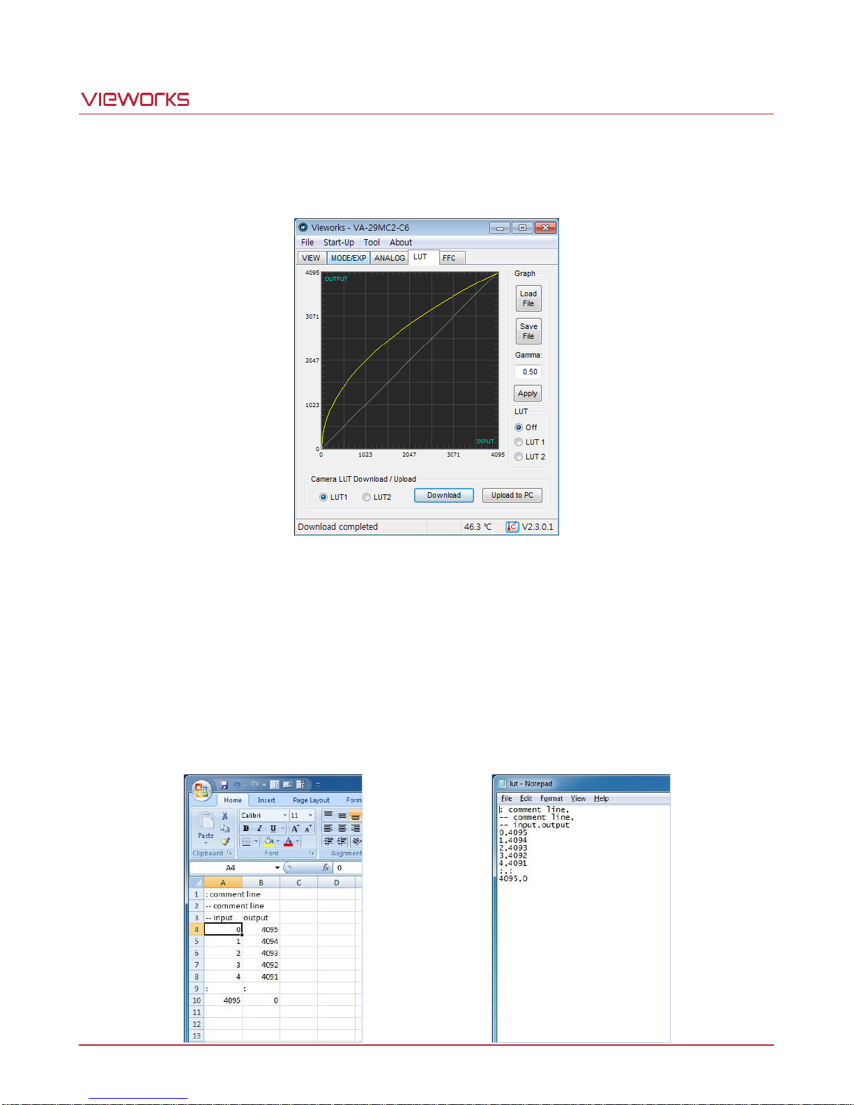
3. Once the download is complete, the Download completed message will appear at the bottom of the
window.
B.2 CSV File Download
1. Create a LUT table in Microsoft Excel format as shown in the left picture below and save as a CSV file
(*.csv). The picture in the right shows the created file opened with Notepad. Once the file is created
completely, change the .csv file extension to .lut. The following rules need to be applied when creating the
file.
Lines beginning with ‘:’ or ‘—‘ are treated as notes.
You must enter all output values corresponding to input values from 0 to 4095.
Page 72 of 78 VW40-158-009
Page 73
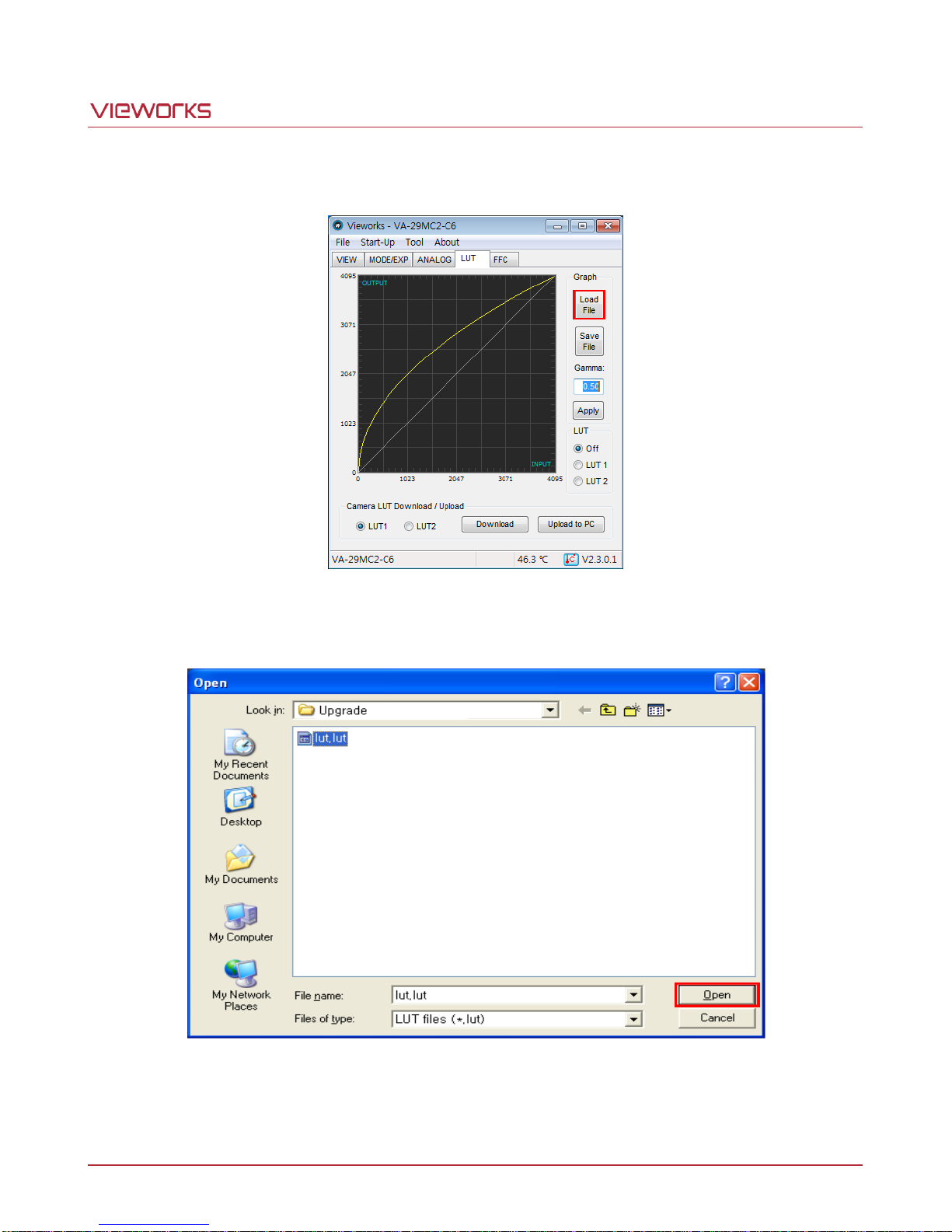
VA-29MC2-6
2. Click Load File in the LUT tab.
3. Search and select the created file and click Open.
4. Select LUT1 or LUT2 as a location to store the data and click Download. The subsequent processes are
identical to those of Gamma Graph Download.
Page 73 of 78 VW40-158-009
Page 74
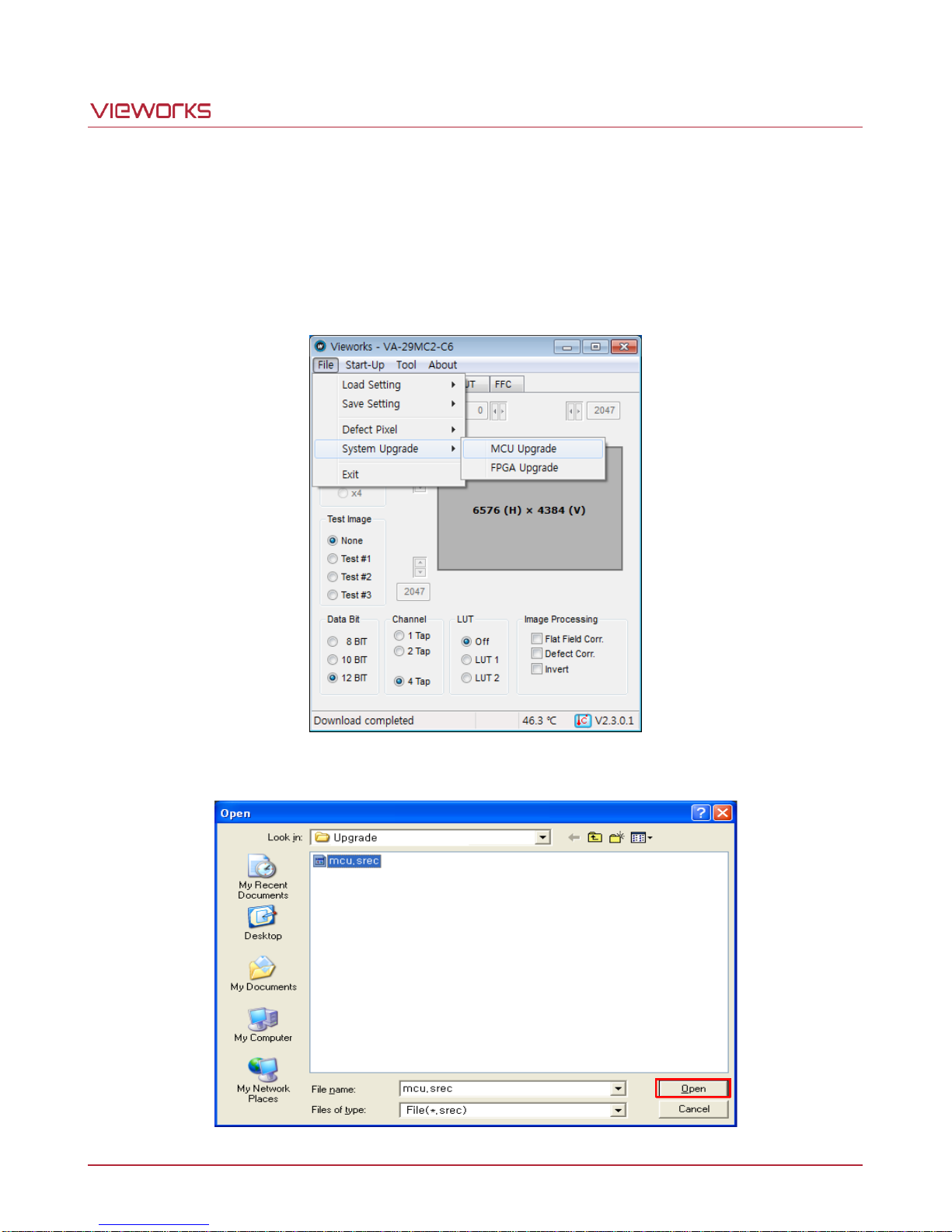
VA-29MC2-6
Appendix C Field Upgrade
C.1 MCU
1. Select File > System Upgrade -> MCU Upgrade in the Configurator.
2. Search and select the provided MCU upgrade file (*.srec) and click Open.
Page 74 of 78 VW40-158-009
Page 75
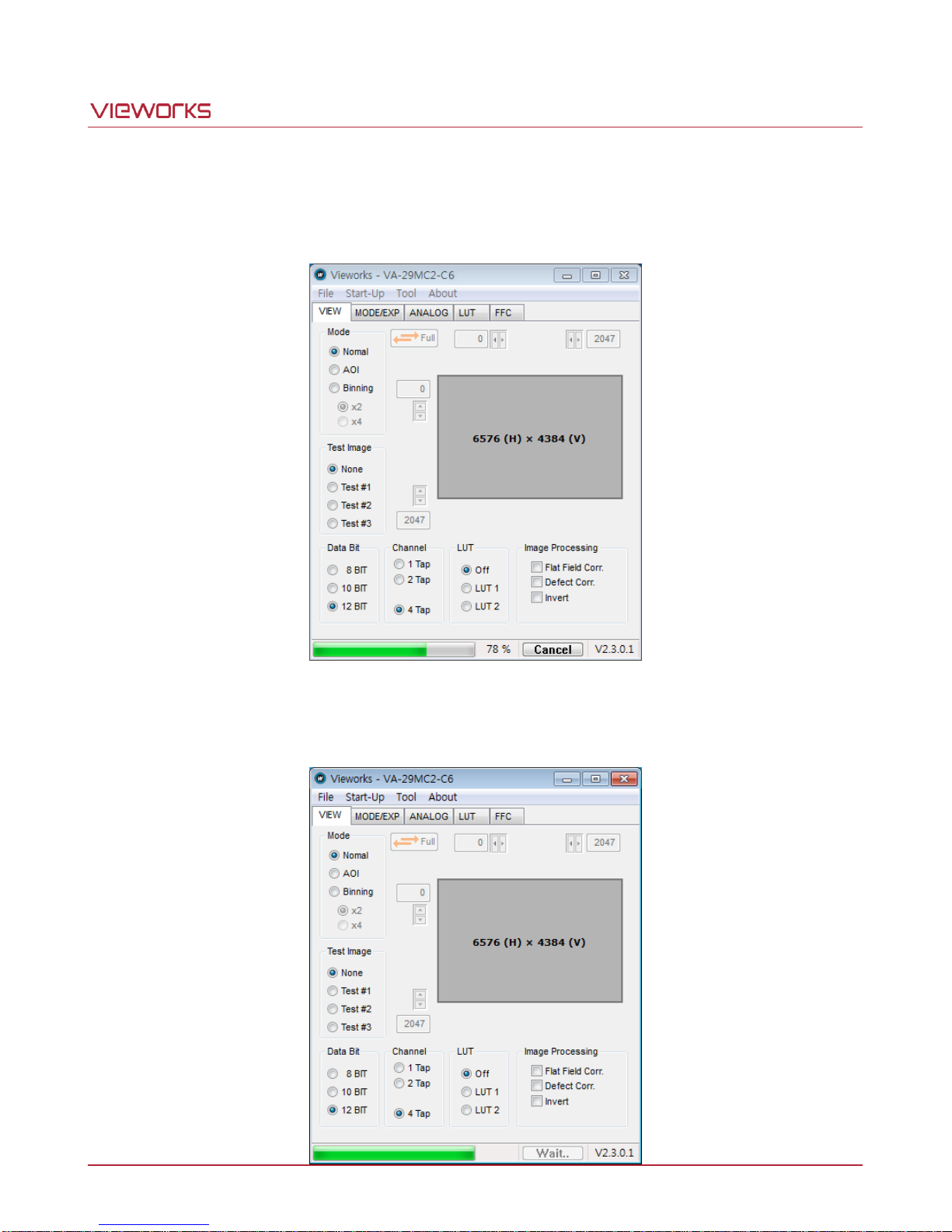
VA-29MC2-6
3. The Configurator starts downloading MCU upgrade file to the camera and downloading status is displayed
at the bottom of the window. If you want to cancel the upgrade process, clock Cancel. This process may
require several minutes to complete.
4. Once the download is complete, the saving process will begin. If a power failure occurs during the saving
process, the camera cannot be restored. Make sure that the power connection is secured.
Page 75 of 78 VW40-158-009
Page 76
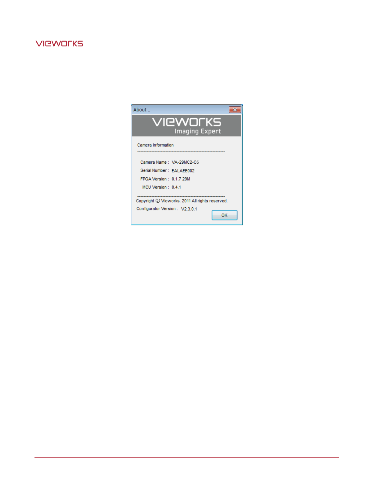
VA-29MC2-6
5. Once all the processes are complete, turn the camera power off and turn it back on again. Select Tool >
Terminal and enter the “gmv" command to confirm the version. Or, select About > Camera Info to confirm
the MCU version.
Page 76 of 78 VW40-158-009
Page 77
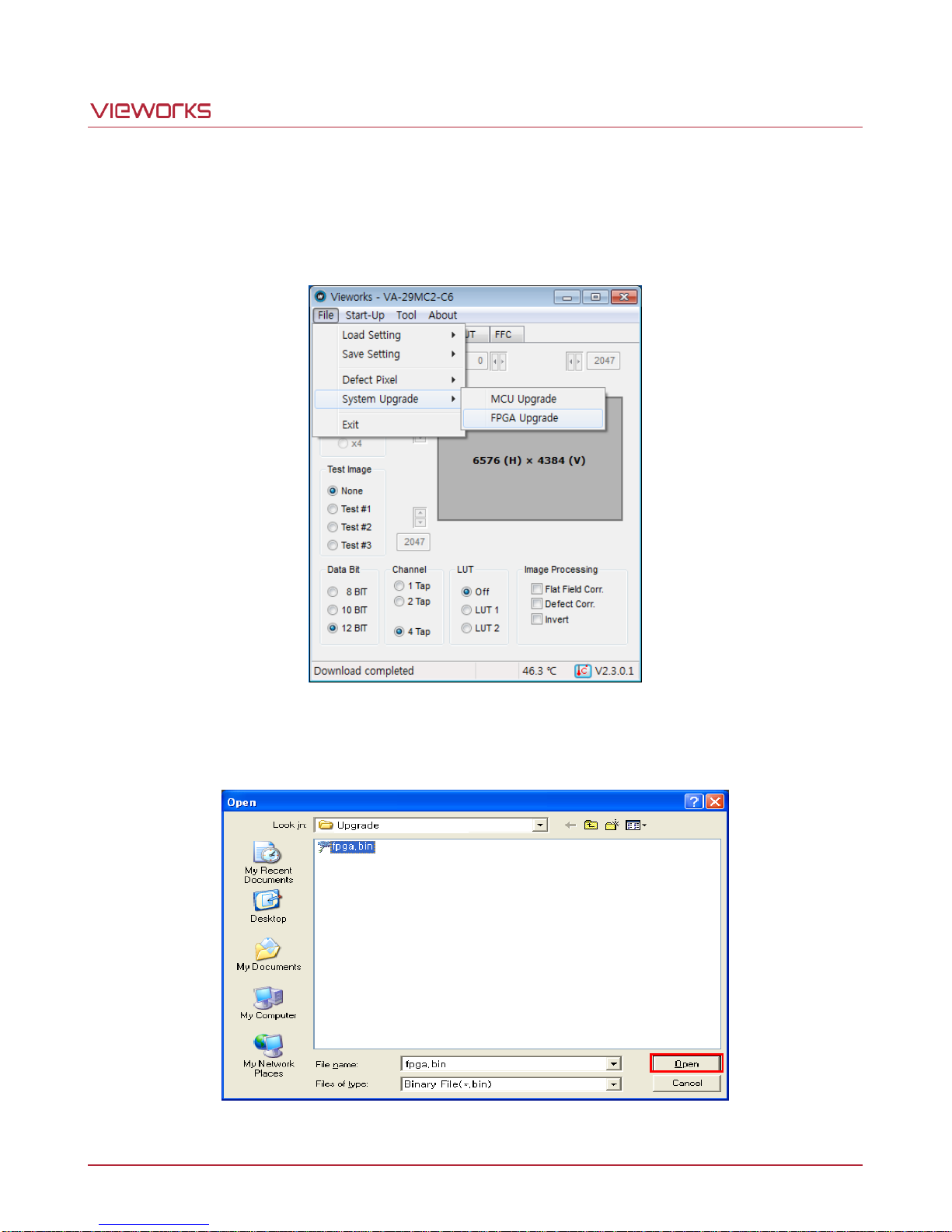
VA-29MC2-6
C.2 FPGA
1. Select File > System Upgrade > FPGA Upgrade in the Configurator.
2. Search and select the provided FPGA upgrade file (*.bin) and click Open.
3. The subsequent processes are identical to those of MCU upgrade.
Page 77 of 78 VW40-158-009
Page 78
 Loading...