


User Manual
English

VA GigE series
Revision History
Version Date Description
1.0 2013-01-14 Draft
Added description of M5 set screws for tilt adjustment
1.1 2013-06-14
Revised spectral response according to the updated TSI datasheets
Corrected errors on RJ-45 Jack specifications
Deleted the DataRoiDispla y parameter
2 of 99 RA14-131-003

VA GigE series
Contents
1 Precautions ....................................................................................................................... 6
2 Warranty ............................................................................................................................ 6
3 Compliance & Certifications ............................................................................................ 7
3.1 FCC Compliance ............................................................................................................. 7
3.2 CE : DoC ......................................................................................................................... 7
3.3 KC ................................................................................................................................... 7
4 Package Components ...................................................................................................... 8
5 Product Specifications ..................................................................................................... 9
5.1 Model .............................................................................................................................. 9
5.2 Specifications ................................................................................................................ 10
5.3 Camera Block Diagram ................................................................................................. 12
5.4 Spectral Response ........................................................................................................ 13
5.4.1 Mono Camera Spectral Response ................................................................................................. 13
5.4.2 Color Camera Spectral Response .................................................................................................. 16
5.5 Mechanical Specification ............................................................................................... 19
6 Installation ....................................................................................................................... 21
6.1 Mount Plate ................................................................................................................... 21
6.2 Precaution to Center the Image Sensor ......................................................................... 22
6.3 Precaution about Blurring Compared to Center ............................................................. 22
6.4 Installing Vieworks Imaging Solution .............................................................................. 22
7 Camera Interface ............................................................................................................. 23
7.1 General Description ....................................................................................................... 23
7.2 RJ-45 Jack .................................................................................................................... 24
7.3 Control Receptacle ........................................................................................................ 25
7.4 Power Input Receptacle ................................................................................................. 26
7.5 Trigger Input Circuit ....................................................................................................... 27
7.6 Strobe Output Circuit ..................................................................................................... 27
8 Acquisition Control ......................................................................................................... 28
8.1 Overview ....................................................................................................................... 28
8.2 Acquisition Start/Stop Commands and Acquisition Mode ............................................... 31
3 of 99 RA14-131-003

VA GigE series
8.3 Exposure Start Trigger ................................................................................................... 32
8.3.1 Trigger Mode .................................................................................................................................. 32
8.3.2 Using a Software Trigger Signal ..................................................................................................... 35
8.3.3 Using an External Trigger Signal .................................................................................................... 36
8.3.4 Trigger Delay .................................................................................................................................. 39
8.4 Setting the Exposure Time ............................................................................................. 40
8.5 Overlapping Exposure with Sensor Readout ................................................................. 41
8.6 Real Exposure ............................................................................................................... 44
8.6.1 Timed Exposure Mode .................................................................................................................... 44
8.6.2 Trigger Width Exposure Mode ........................................................................................................ 45
8.7 Acquisition Timing Chart ................................................................................................ 47
8.8 Maximum Allowed Frame Rate ...................................................................................... 49
8.8.1 Increasing the Maximum Allowed Frame Rate ............................................................................... 50
9 Camera Features ............................................................................................................. 51
9.1 Image R egion of Interest ............................................................................................... 51
9.2 Binning .......................................................................................................................... 55
9.3 Sensor Tap Settings ...................................................................................................... 57
9.4 Pixel Format .................................................................................................................. 60
9.5 Pixel Clock..................................................................................................................... 65
9.6 Stream Hold................................................................................................................... 66
9.7 Inter-Packet Delay ......................................................................................................... 67
9.8 Data ROI (Color Cameras) ............................................................................................ 68
9.9 Balance White Auto (Color Cameras) ............................................................................ 70
9.10 Gain and Black Level ..................................................................................................... 71
9.10.1 Analog Domain ....................................................................................................................... 71
9.10.2 Digital Domain ......................................................................................................................... 72
9.11 LUT ............................................................................................................................... 73
9.12 Defective Pixel Correct io n ............................................................................................. 75
9.12.1 Correction Method .................................................................................................................. 75
9.12.2 Correction Method in Binning Mode ....................................................................................... 76
9.13 Flat Field Correction ...................................................................................................... 77
9.14 Temperature Monitor ..................................................................................................... 80
9.15 Fan Control (Only available on VA-29MG2) ................................................................... 80
9.16 Status LED .................................................................................................................... 81
9.17 Test Image ..................................................................................................................... 82
4 of 99 RA14-131-003

VA GigE series
9.18 Reverse X ..................................................................................................................... 84
9.19 Digital IO Control ........................................................................................................... 85
9.20 Event Control ................................................................................................................. 86
9.21 Device User ID .............................................................................................................. 87
9.22 Device Reset ................................................................................................................. 87
9.23 User Set Control ............................................................................................................ 88
9.24 Field Upgrade ................................................................................................................ 88
Appendix A Defective Pixel Map Download ................................................................... 89
Appendix B LUT Download ............................................................................................. 91
B.1 Luminance LUT ............................................................................................................. 91
B.1.1 Gamma Graph Download ............................................................................................................... 91
B.1.2 CSV File Download ........................................................................................................................ 93
Appendix C Field Upgra de ............................................................................................... 95
C.1 MCU .............................................................................................................................. 95
C.2 FPGA ............................................................................................................................ 97
C.3 XML ............................................................................................................................... 98
5 of 99 RA14-131-003

VA GigE series
1 Precautions
General
Do not drop, damage, disassemble, repair or alter the device.
Do not let children touch the device without supervision.
Do not use the device for any other purpose than specified.
Contact your nearest distributor in case of trouble or problem.
Installation and Maintenance
Do not install the device in a place subject to direct sun light, humidity, dust or soot.
Do not place magnets near the product.
Do not place the device next to heating equipment.
Be careful not to let liquid like water, drinks or chemicals leak inside the device.
Clean the device often to remove dust on it.
In clearing, do not splash water on the device but wipe it out with a smooth cloth or towel.
Power Supply
Applying incorrect power can dam age the camera. If the voltage applied to the c am era is
greater or less than the camera’s nominal voltage, the camera may be damaged or
operate erratically. Please refer to
※ Vieworks Co., Ltd. does NOT provide power supplies with the devices.
5.2 Specifications for the camera’s nominal voltage.
2 Warranty
Do not open the housing of the camera. The warranty becomes void if the housing is opened.
For information about the warranty, please contact your local dealer or factory representative.
6 of 99 RA14-131-003

VA GigE series
3 Comp liance & Certifications
3.1 FCC Compliance
This equipment has been tested and found to comply with the limits for a Class A digital device, pursuant to part
15 of the FCC Rules. These limits are designed to provide reasonable protection against harmful interference
when the equipment is operated in a commercial environment. This equipment generates, uses, and can radiate
radio frequency energy and, if not installed and used in accordance with the instruction manual, may cause
harmful interference to radio communications. Operation of this equipment in a residential area is likely to cause
harmful interference in which case the user will be required to correct the interference at his own expenses.
3.2 CE : DoC
EMC Directive 2004/108/EC.
Testing Standard EN 55022:2006+A1: 200 7, EN 5502 4: 1998 + A1:2001+A2:2003
Class A
3.3 KC
KCC Statement
Type Description
Class A
(Broadcasting Comm unic ation
Device for Office Use)
This device obtained EMC registration for office use (Class A), and may
be used in places other than home. Sellers and/or users need to take
note of this.
7 of 99 RA14-131-003

VA GigE series
4 Package Components
Package Components
VA Camera with C mount or VA Camera with F mount
Mount Plate (Optional)
M5 Set Screws for Tilt Adjustment (Provided only with F-mount camera)
* VA-29MG2 will be offered with a cooling fan. It is also available without the fan upon request.
You can adjust the tilt using the M5 set screws, however it is not recommended since it is
adjusted as factory default settings.
If the tilt settings need to be adjusted inevitably, please contact your local dealer or
factory representative for technical support.
8 of 99 RA14-131-003

VA GigE series
5 Product Specifications
5.1 Model
VA GigE series is a progressive scan, high-resolution industrial area scan cameras. The camera uses an
interline transfer CCD from Truesense Imaging, Inc. (formerly Kodak Imaging Solution) and provides superior
noise performance resulting in high dynamic range. All features of VA GigE series can be programmed and
easily updated in the field through Gigabit Ethernet interface. The camera is developed based on GenICam
standard. The image processing and controls of VA GigE series are based on embedded FPGA with a 32 bit
microprocessor.
Main Features
Normal and High Speed Operation Modes
×1, ×2, ×3, ×4, ×8 Horizontal and Vertical Binning
Real Exposure
Stream Hold
Inter-Packet Delay
Camera Image Memory: 128MB
Field Upgradable Firmware
Pixel Defect Correction (Binning Mode: 2×2, 4×4)
Excellent Anti-Blooming and Anti-Smear
9 of 99 RA14-131-003

VA GigE series
5.2 Specifications
VA GigE series technical specifications are as follows.
VA GigE Series VA-1MG2 VA-2MG2 VA-2MG2 (HD)
Active Image (H × V) 1024 × 1024 1600 × 1200 1920 × 1080
Sensor Type
Pixel size
Sensor Output 1 or 2 Tap
Video Output 8/10/12 bits
Dynamic Range
Mono Mono8, Mono10, Mono10 packed, Mono12, Mono12 packed
Output Format
Color Bayer8, Bayer10, Bayer10 packed, Bayer12, Bayer12 packed
Camera Interface Gigabit Ethernet
Electronic Shutter Global Shutter
Max. Frame Rate at Full Resolution 40 fps / 72 fps 22 fps / 42 fps 21 fps /39 fps
Pixel Clock
Shutter Speed (10 ㎲ step) 7 ㎲~ 7s
Partial Scan (Max. Speed) 193 fps at 120 Lines 110 fps at 150 Lines 107 fps at 120 Lines
Binning
Lookup T able G=1.0, User Defined Lookup Table (LUT)
Truesense Imaging
KAI-01050
×1, ×2, ×3, ×4, ×8 (Horizontal and Vertical Independent)
Truesense Imaging
KAI-02050
5.5 ㎛ × 5.5 ㎛
> 64 ㏈
40 / 50 ㎒
Truesense Imaging
KAI-02150
Black Level Adj us table (0 ~ 127 LSB at 12 bit, 256 steps)
Analog Gain
Exposure Mode Timed Exposure, Trigger Width Exposure, Double Exposure
External Trigger
Software Trigger Asynchronous, Program mable via Camera API
Camera Image Memory 128 MB
Lens Mount C-mount or F-mount
Power 10 ~ 15 V DC, Max. 6W
Environmental
Mechanical
Table 5.1 Specifications of VA GigE Series (VA-1/2MG2)
10 of 99 RA14-131-003
×1 ~ ×40 (0 ~ 32 ㏈)
3.3 V ~ 24.0 V, 10 ㎃, Asynchronous, optically isolate d
Operating: -5℃ ~ 40℃, Storage : -40℃ ~ 70℃
68 ㎜ x 68 ㎜ x 54 ㎜, 420 g (with C-mount)
68 ㎜ x 68 ㎜ x 83 ㎜, 460 g (with F-mount)

VA GigE series
VA GigE Series VA-4MG2 VA-8MG2 VA-29MG2
Active Image (H × V) 2336 × 1752 3296 × 2472 6576 × 4384
Truesense Imaging
Truesense Imaging
Truesense Imaging
Sensor Type
KAI-04050
Pixel size
KAI-08050
5.5 ㎛ × 5.5 ㎛
KAI-29050
Sensor Output 1 or 2 Tap
Video Output 8/10/12 bits
Dynamic Range
> 64 ㏈
Mono Mono8, Mono10, Mono10 packed, Mono12, Mono12 packed
Output Format
Color Ba yer8, Ba yer1 0, Bayer10 packed, Bayer12, Bayer12 packed
Camera Interface Gigabit Ethernet
Electronic Shutter Global Shutter
Max. Frame Rate at Full
10 fps / 20 fps 5 fps / 10 fps 1.2 fps / 2.3 fps
Resolution
Pixel Clock
40/50 ㎒ 30/40 ㎒
Shutter Speed (10 ㎲ step) 8 ㎲~ 7 s 9 ㎲~ 7 s 22 ㎲~ 7 s
Partial Scan (Max. Speed) 82 fps at 200 Lines 48 fps at 300 Lines 8.8 fps at 500 Lines
Binning
×1, ×2, ×3, ×4, ×8 (Horizontal and Vertical Independent)
Lookup T able G=1.0, User Defined Lookup Table (LUT)
Black Level Adj us table (0 ~ 127 LSB at 12 bit, 256 steps)
Analog Gain
×1 ~ ×40 (0 ~ 32 ㏈)
Exposure Mode Timed Exposure, Trigger Width Exposure , Doubl e Exp os ur e
External Trigger
3.3 V ~ 24.0 V, 10 ㎃, Asynchronous, optically isolate d
Software Trigger Asynchronous, Program mable via Camera API
Camera Image Memory 128 MB
Lens Mount C-mount or F-mount
Power 10 ~ 15 V DC, Max. 6W
Environmental
68 ㎜×68 ㎜× 54 ㎜, 420 g (with C-mount)
Operating: -5℃ ~ 40℃, Storage : -40℃ ~ 70℃
74 ㎜×65 ㎜×103 ㎜,
Mechanical
68 ㎜×68 ㎜×83 ㎜, 460 g (with F-mount)
550 g (with F-mount)
Table 5.2 Specifications of VA GigE Series (VA-4/8/29MG2)
11 of 99 RA14-131-003

VA GigE series
Image Processing
Control Logic
Micro Controller
FPGA
CCD
Sensor
DDR2
SDRAM
Ethernet
Controller
V Driver
H Driver
ADC
(
14bit)
FLASH
EEPROM
Line Driver
Optocoupler
Prog.output
Ext.trigger
Network
5.3 Camera Block Diagram
Figure 5.1 Camera Block Diagram
All controls and data processing of VA GigE cameras are carried out in one FPGA chip. The FPGA generally
consists of a 32 bit RICS Micro-Controller and Processing & Control Logic. The Micro-Controller receives
commands from the user through the Gigabit Ethernet interface and then processes them. The FPGA controls
the Timing Generators (TGs) and the Analog Front End (AFE) chips where the TGs generate CCD control
signals and AFE chips convert analog CCD output to digital values to be accepted by the Processing & Control
Logic. The Processing & Control Logic processes the image data received from AFE and then transmits data
through the Gigabit Ether n et interface. And also, the Processing & Control Logic controls the trigger input and
output signal which are sensitive to time. Furthermore, DDR2 for operating Micro-Controller and for used as
Gigabit Ethernet frame buffer, SDRAM for used as a frame buffer to process images, Gigabit Ethernet Controller
and Flash memory for saving system codes and defect coordinates are installed outside FPGA.
12 of 99 RA14-131-003

VA GigE series
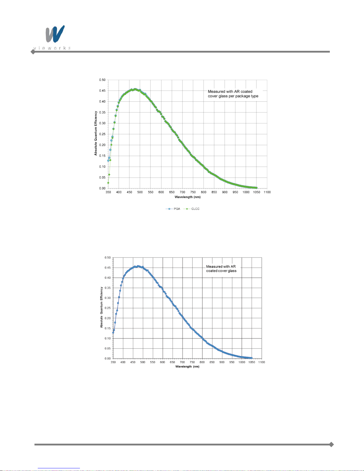
5.4 Spectral Response
5.4.1 Mono Camera Spectral Response
The following graphs show the spectral response for VA GigE series monochrome cameras.
Figure 5.2 VA-1MG2-M70 Spectral Response
Figure 5.3 VA-2MG2-M42 Spectral Response
13 of 99 RA14-131-003
VA GigE series
Figure 5.4 VA-2MG2-M39 Spectral Response
Figure 5.5 VA-4MG2-M20 Spectral Response
14 of 99 RA14-131-003

VA GigE series
Figure 5.6 VA-8MG2-M10 Spectral Response
Figure 5.7 VA-29MG2-M2 Spectral Response
15 of 99 RA14-131-003

VA GigE series
5.4.2 Color Camera Spectral Response
The following graphs show the spectral response for VA GigE series color cameras.
Figure 5.8 VA-1MG2-C70 Spectral Response
Figure 5.9 VA-2MG2-C42 Spectral Response
16 of 99 RA14-131-003

VA GigE series
Figure 5.10 VA-2MG2-C39 Spectral Response
Figure 5.11 VA-4MG2-C20 Spectral Response
17 of 99 RA14-131-003

VA GigE series
Figure 5.12 VA-8MG2-C10 Spectral Response
Figure 5.13 VA-29MG2-C2 Spectral Response
18 of 99 RA14-131-003

VA GigE series
5.5 Mechanical Specification
The camera dimensions in millimeters are as shown in the following figure.
Figure 5.14 VA GigE Series C-mount Mechan ical Dim ensio n
19 of 99 RA14-131-003

VA GigE series
Figure 5.15 VA GigE Series F-mount Mechanical Dimension
20 of 99 RA14-131-003

VA GigE series
6 Installation
The following instructions as s um e that you have installed an Ethernet Card including related software and
Vieworks Imaging Solution in your PC. For more information, refer to your Vieworks Imaging Solution
Installation Manual.
To connect the camera to your PC, follow the steps below:
1. Make sure that the power supply is not connected to the camera and your PC is turned off.
2. Plug one end of an Ethernet cable into the RJ45 jack on the camera and the other end of the Ethernet cable
into the Ethernet Card in your PC.
3. Connect the plug of the power adaptor to the power input receptacle on the camera.
4. Plug the power adaptor into a working electrical outlet.
5. Verify all the cable connections are secure.
6.1 Mount Plate
The Mount Plate is provided as an optional item.
The camera can be fixed without using this Mount Plate.
21 of 99 RA14-131-003

VA GigE series
6.2 Precaution to Center the Image Sensor
Users do not need to center the image sensor as it is adjusted as factory default settings.
When you need to adjust the center of the image sensor, please contact your local dealer or the
manufacturer for technical assistance.
6.3 Precaution about Blurring Compared to Center
Users do not need to adjust the tilt as it is adjusted as factory default settings.
If the tilt settings need to be adjusted inevitably, please contact your local dealer or factory representative for
technical support.
6.4 Installing Vieworks Imaging Solution
You can download the Vieworks Imaging Solution at machinevision.vieworks.com.
You should perform the software installation first and then the hardware installation.
22 of 99 RA14-131-003

VA GigE series
7 Camera Interface
7.1 General Description
As shown in the following figure, 3 types of connectors and status indicator LED are located on the back of the
camera and have the functions as follows:
① Status LED: displays power status and operation mode.
② RJ-45 Jack: controls video data and the camera.
③ 4 pin Control Receptacle: inputs external trigger signal and outputs strobe.
④ 6 pin Power Input Receptacle: supplies power to the camera.
①
②
③
④
Figure 7.1 VA GigE Series Back Panel
23 of 99 RA14-131-003

VA GigE series
7.2 RJ-45 Jack
The 8-pin RJ-45 jack provides Ethernet access to the camera. Pin assignments for the RJ-45 jack adhere to the
Ethernet standard.
Figure 7.2 RJ-45 Jack
PAIR List Pin Signal Name Type Description
PA IR 0
PA IR 1
PA IR 2
PA IR 3
1 +TXA Differential Gigabit Ethernet Transceiver
2 -TXA Differential Gigabit Ethernet Transceiver
3 +TXB Differential Gigabit Ethernet Transceiver
6 -TXB Differential Gigabit Ethernet Transceiver
4 +TXC Differential Gigabit Ethernet Transceiver
5 -TXC Differential Gigabit Ethernet Transceiver
7 +TXD Differential Gigabit Ethernet Transceiver
8 -TXD Differential Gigabit Ethernet Transceiver
Table 7.1 Pi n Assignments for the RJ-45 Jack
24 of 99 RA14-131-003

VA GigE series
1
2
4
3
7.3 Control Receptacle
The control receptacle is a Hirose 4 pin connector (part # HR10A-7R-4S) and consists of an external trigger
signal input and strobe output port. The pin assignments and configurations are as follows:
Figure 7.3 Pin Assignments for 4 Pin Control Receptacle
Pin Number Signal Type Description
1 Trigger Input + Input Voltage difference of
3.3 V ~ 24 V, 10 ㎃,
2 Trigger Input - Input
optically isolated
3 DC Ground - DC Ground
4
Programmable Output
Output
(Default: Strobe Out)
3.3 V TTL Output
Output resistance : 47 Ω
Table 7.2 Pin Configurations for Control Connector
The mating connector is a Hirose 4 pin plug (part # HR10A-7P-4P) or the equivalent connectors.
25 of 99 RA14-131-003

VA GigE series
1
2
3 4
5
6
7.4 Power Input Receptacle
The power input receptacle is a Hirose 6 pin connector (part # HR10A-7R-6PB). The pin assignments and
configurations are as follows:
Figure 7.4 Pin Assignments for Power Input Receptacle
Pin Number Signal Type Description
1, 2 , 3 + 12V DC Input DC Power Input
4 , 5 , 6 DC Ground Input DC Ground
Table 7.3 Pi n Configurations for Power Input Receptacle
Connecting the power cable to the camera can be made by using the Hirose 6 pin plug (part # HR10A-7P-6S) or
the equivalent. The power adaptor is recommended to have at least 1A current output at 12 V DC ±10% voltage
output (Users need to purchase the power adaptor separately).
Precaution for Power Input
Make sure the power is turned off before connecting the power cord to the camera.
Otherwise, damage to the camera may result.
If the camera input voltage is greater than 16 V, damage to the camera may result.
26 of 99 RA14-131-003

VA GigE series
2.2K
47
+5.0V
Trigger_Input
1K
Trigger-
Camera
180
GND
Y our GND
GND
GND
PSD24C
Trigger+
J- FET
Trigger
1
2
3
4
HR10-7R-4SB
+3.3~24.0V
PSD24C
Strobe_Output
Line Driver
2
4
5
3
47
GND
+3.3V
47
Y our GND
Strobe
GND
Camera
0V
+3.3V
1
2
3
5
4
6
HR10-7R-6SB
7.5 Trigger Input Circuit
The following figure shows trigger signal input circuit of the 4-pin connector. Transmitted trigger signal is applied
to the internal circuit through a photo coupler. Minimum trigger width that can be recognized by the camera is 1
㎲. If transmitted trigger signal is less than 1 ㎲, the camera will ignore the trigger signal. External trigger circuit
example is shown below.
7.6 Strobe Output Circuit
The strobe output signal comes out through a 3.3 V output level of Line Driver IC. You can change the strobe
output by setting the Digital IO Control (Refer to chapter
27 of 99 RA14-131-003
Figure 7.5 Trigger Input Schematic
9.19 Digital IO Control).
Figure 7.6 Strobe Output Sch ematic

VA GigE series
8 Acquisition Control
This chapter provides detailed information about controlling image acquisition.
Triggering image acquisition
Setting the exposure time
Controlling the camera’s image acquisition rate
Variation of the camera’s maximum allowed image acquisition rate according to the camera settings
8.1 Overview
This section presents an overview of the elements involved with controlling the acquisition of images.
Three major elements are involved in controlling the acquisition of images:
Acquisition Start and Acquisition Stop commands and the Acquisition Mode parameter
The exposure start trigger
Exposure time control
When reading the explanations in the overview and in this entire chapter, keep in mind that
the term frame is typically used to mean a single acquired image.
Acquisition Start and Stop Commands and the Acquisition Mode
The Acquisition Start command prepares the camera to acquire frames. The camera cannot acquire frames
unless an Acquisition Start command has first been executed.
A parameter called the Acquisition Mode has a direct bearing on how the Acquisition Start command
operates.
If the Acquisition Mode parameter is set to Single Frame, you can only acquire one frame after executing an
Acquisition Start command. When one frame has been acquired, the Acquisition Start command will expire.
Before attempting to acquire another frame, you must execute a new Acquisition Start command.
If the Acquisition Mode parameter is set to Continuous, an Acquisition Start command does not expire after
a single frame is captured. Once an Acquisition Start command has been executed, you can acquire as many
frames as you like. The Acquisition Start command will remain in effect until you execute an Acquisition Stop
command. Once an Acquisition Stop command has been executed, the camera will not be able to acquire
frames until a new Acquisition Start command is executed.
28 of 99 RA14-131-003

VA GigE series
Exposure Start Trigger
Applying an exposure start trigger signal to the camera will exit the camera from the waiting for exposure start
trigger acquisition status and will begin the process of exposing and reading out a frame (see Figure 8.1). As
soon as the camera is ready to accept another exposure start trigger signal, it will return to the waiting for
exposure start trigger acquisition status. A new exposure start trigger signal can then be applied to the camera to
begin another frame exposure.
The exposure start trigger has two modes: off and on.
If the Trigger Mode parameter is set to Off, the camera will generate all required exposure start trigger signals
internally, and you do not need to apply exposure start trigger signals to the camera. The rate at which the
camera will generate the signals and acquire frames will be determined by the way that you set several frame
rate related parameters.
If the Trigger Mode parameter is set to On, you must trigger exposure start b y applying exposure start trigger
signals to the camera. Each time a trigger signal is applied, the camera will begin a frame exposure. When
exposure start is being triggered in this manner, it is important that you do not attempt to trigger frames at a rate
that is greater than the maximum allowed (There is a detailed explanation about the maximum allowed frame
rate at the end of this chapter.). Exposure start trigger signals applied to the camera when it is not in a waiting for
exposure start trigger acquisition status will be ignored.
29 of 99 RA14-131-003
Figure 8.1 Exposure Start Triggering

VA GigE series
Applying Trigger Signals
The paragraphs above mention "applying a trigger signal". There are two ways to apply an exposure start trigger
signal to the camera: via software or via external (commonly referred to as hardware).
To apply trigger signals via Software, you must set the Trigger Source parameter to Software. At that point,
each time a Trigger Software command is executed, the exposure start trigger signal will be applied to the
camera.
To apply trigger signals via External, you must set the Trigger Source parameter to External. At that point,
each time a proper electrical signal is applied to the camera, an occurrence of the exposure start trigger signal
will be recognized by the camera.
Exposure Time Control
When an exposure start trigger signal is applied to the camera, the camera will begin to acquire a frame.
A critical aspect of frame acquisition is how long the pixels in the camera’s sensor will be exposed to light during
the frame acquisition.
If the Trigger Source parameter is set to Software, a parameter called the Exposure Time will determine the
exposure time for each frame. At this point, you must set the Exposure Mode parameter to Timed.
If the Trigger Source param eter is s et to External, there ar e t wo modes of operation: Timed and Trigger Width.
With the Timed mode, the Exposure Time parameter will determine the exposure time for each frame.
With the Trigger Width mode, the way that you manipulate the rise and fall of the external signal will determine
the exposure time. The Trigger Width mode is especially useful if you want to change the exposure time from
frame to frame.
30 of 99 RA14-131-003

VA GigE series
8.2 Acquisition Start/Stop Commands and Acquisition Mode
Executing an Acquisition Start command prepares the camera to acquire frames. You must execute an
Acquisition Start command before you can begin acquiring frames. Executing an Acquisition Stop command
terminates the camera’s ability to acquire frames. When the camera receives an Acquisition Stop command:
If the camera is not in the process of acquiring a frame, its ability to acquire frames will be terminated
immediately.
If the camera is in the process of acquiring a frame, the frame acquisition process will be allowed to finish
and the camera’s ability to acquire new frames will be terminated.
The camera’s Acquisition Mode parameter has three settings: Single Frame, Multi-Frame and Continuous.
The use of Acquisition Start and Acquisition Stop commands and the camera’s Acquisition Mode parameter
setting are related.
If the camera’s Acquisition Mode parameter is set to Single Frame, after an Acquisition Start command has
been executed, a single frame can be acquired. When acquisition of one frame is complete, the camera will
execute an Acquisition Stop command internally and will no longer be able to acquire frames. To acquire
another frame, you must execute a new Acquisition Start command.
If the camera’s Acquisition Mode parameter is set to Multi-Frame, after an Acquisition Start command has
been executed, exposure start can be triggered as many as specified by the Acquisition Frame Count
parameter. The camera will continue to react to exposure start trigger signals until the number of exposure start
trigger signals it has received is equal to the current Acquisition Frame Count parameter setting. At that point,
the Acquisition Start command will expire. Before attempting to acquire another frame, you must execute a
new Acquisition Start command.
With Single Frame or Multi-Frame Acquisition Mode, if you execute another Acquisition
Start command while the camera is in the process of acquiring a frame, an error may occur.
If the camera’s Acquisition Mode parameter is set to Continuous, after an Acquisition Start command has
been executed, exposure start can be triggered as desired. Each time an exposure start trigger is applied while
the camera is in a waiting for exposure start trigger acquisition status, the camera will acquire and transmit a
frame. The camera will retain the ability to acquire frames until an Acquisition Stop command is executed.
Once the Acquisition Stop command is received, the camera will no longer be able to acquire frames.
When the camera's Acquisition Mode is set to Single Frame, the maximum possible acquisition frame rate for
a given ROI cannot be achieved. This is true because the camera performs a complete internal setup cycle for
each single frame and because it cannot be operated with Trigger Overlap. To achieve the maximum possible
acquisition frame rate, set the Acquisition Mode to Continuous and Trigger Overlap to Readout.
31 of 99 RA14-131-003

VA GigE series
8.3 Exposure Start Trigger
The exposure start trigger is used to begin frame acquisition. Exposure start trigger signals can be generated
within the camera or may be applied externa lly as Software or External exposure start trigger signals. If an
exposure start trigger signal is applied to the camera, the camera will begin to expose a frame.
8.3.1 T rigger Mode
The main parameter associated with the exposure start trigger is the Trigger Mode parameter. The Trigger
Mode parameter for the exposure start trigger has two available settings: Off and On.
8.3.1.1 Trigger Mode = Off
When the Trigger Mode parameter is set to Off, the camera will generate all required exposure start trigger
signals internally, and you do not need to apply exposure start trigger signals to the camera.
With the Trigger Mode set to Off, the way that the camera will operate the exposure start trigger depends on the
setting of the camera’s Acquisition Mode parameter:
Single Frame: The camera will automatically generate a single exposure start trigger signal whenever it
receives an Acquisition Start command.
Multi-Frame: The camera will automatically begin generating exposure start trigger signals as many as
specified by the Acquisition Frame Count parameter when it receives an Acquisition Start command.
The camera will continue to generate exposure start trigger signals until the number of exposure start trigger
signals it has received is equal to the current Acquisition Frame Count parameter setting or until it
receives an Acquisition Stop command.
With Single Frame or Multi-Frame Acquisition Mode, if you execute another Acquisition
Start command while the camera is in the process of acquiring a frame, an error may occur.
When the Acquisition Mode param eter is set to Multi-Frame, you must set the value of the
camera’s Acquisition Frame Count parameter. The value of the Acquisition Frame Count
can range from 1 to 255.
32 of 99 RA14-131-003

VA GigE series
Continuous: The camera will automatically begin generating exposure start trigger signals when it receives
an Acquisition Start command. The camera will continue to generate exposure start trigger signals until it
receives an Acquisition Stop command.
Free Run
When you set the Trigger Mode parameter to Off and the Acquisition Mode parameter
to Continuous, the camera will generate all required trigger signals internally. When the
camera is set this way, it will constantly acquire images without any need for triggering by
the user. This use case is commonly referred as “free run”.
When you operate the camera in free run, you must set the Trigger Overlap parameter
to Readout to achieve optimal camera performance.
The rate at which the exposure start trigger signals are generated may be determined by the camera’s
Acquisition Frame Rate parameter:
If the parameter is set to a value less than the maximum allowed frame rate with the current camera settings,
the camera will generate exposure start trigger signals at the rate specified by the parameter setting.
If the parameter is set to a value greater than the maximum allowed frame rate with the current camera
settings, the camera will generate exposure start trigger signals at the maximum allowed frame rate.
Exposure Time Control with Trigger Mode = Off
When the Trigger Mode parameter is set to Off, the exposure time for each frame acquisition is determ ined b y
the value of the camera’s Exposure Time parameter. For more information about the Exposure Time
parameter, see
8.4 Setting the Exposure Time.
33 of 99 RA14-131-003

VA GigE series
8.3.1.2 Trigger Mode = On
When the Trigger Mode parameter is set to On, you must apply an exposure start trigger signal to the camera
each time you want to begin a frame acquisition. The Trigger Source parameter specifies the source signal that
will act as the exposure start trigger signal.
The available settings for the Trigger Source parameter are:
Software: You can apply an exposure start trigger signal to the camera by executing a Trigger Software
command for the exposure start trigger on your computer.
External: You can app l y an exposure start trigger signal to the camera by injecting an externally generated
electrical signal (commonly referred to as a hardware trigger signal) into the Control Receptacle pin 1 on the
camera.
If the Trigger Source parameter is set to External, you must also set the T rigger Activation parameter.
The available settings for the Trigger Activation parameter are:
Rising Edge: Specifies that a rising edge of the electrical signal will act as the exposure start trigger.
Falling Edge: Specifies that a falling edge of the electrical signal will act as the exposure start trigger.
Exposure Time Control with Trigger Mode = On
When the Trigger Mode parameter is set to On and the Trigge r Sou rc e parameter is set to Software, the
exposure time for each frame acquisition is determined by the value of the camera’s Exposure Time parameter.
When the Trigger Mode parameter is set to On and the Trigg er Sou rc e parameter is set to External, the
exposure time for each frame acquisition can be controlled with the Exposure Time parameter or it can be
controlled by manipulating the external trigger signal.
34 of 99 RA14-131-003

VA GigE series
8.3.2 Using a Software Trigger Signal
If the Trigger Mode parameter is set to On and the Trigger Source parameter is set to Software, you must
apply a software trigger signal (exposure start) to the camera to begin each frame acquisition. Assuming that the
camera is in a waiting for exposure start trigger acquisition status, frame exposure will start when the software
trigger signal is received by the camera. Figure 8.2 illustrates frame acquisition with a software trigger signal.
When the camera receives a software trigger signal and begins exposure, it will exit the waiting for exposure
start trigger acquisition status because at that point, it cannot react to a new exposure start trigger signal.
As soon as the camera is capable of reacting to a new exposure start trigger signal, it will automatically return to
the waiting for exposure start trigger acquisition status.
When you are using a software trigger signal to start each frame acquisition, the camera’s Exposure Mode
parameter must be set to Timed. The exposure time for each acquired frame will be determined by the value of
the camera’s Exposure Time parameter.
When you use a software trigger signal to acquire frames, be aware that there is a Trigger
Latency due to the characteristics of the Gi ga bit Eth ernet. Use an external trigger signal to
precisely synchronize the trigger signal with the exposure timing.
Figure 8.2 Frame Acquisition with Software Trigger Signal
When you are using a softwar e t r igger signal to start each frame ac qui s iti on, the frame rate will be
determined by how often y ou apply a software trigger signal to the camera, and you should not attempt to
trigger frame acquisition at a rate that exceeds the maxim um allowed for the current camera settings.
(There is a detailed explanat io n about the maximum allowed frame rate at the end of this chapter . )
Software trigger signals t hat ar e applied to the camera when it is not ready to receive them will be ig nor ed.
35 of 99 RA14-131-003

VA GigE series
8.3.3 Using an External Trigger Signal
If the Trigger Mode parameter is set to On and the Trigger Source parameter is set to External, an externally
generated electrical signal injected into the Control Receptacle pin 1 will act as the exposure start trigger signal
for the camera. This type of trigger signal is generally referred to as a hardware trigger signal.
A rising edge or a falling edge of the external signal can be used to trigger frame acquisition. The Trigger
Activation parameter is used to select rising edge or falling edge triggering.
Assuming that the camera is in a waiting for exposure start trigger acquisition status, frame acquisition will start
whenever the appropriate edge transition is received by the camera.
When the camera receives an external trigger signal and begins exposure, it will exit the waiting for exposure
start trigger acquisition status because at that point, it cannot react to a new exposure start trigger signal. As
soon as the camera is capable of reacting to a new exposure start trigger signal, it will automatically return to the
waiting for exposure start trigger acquisition status.
When the camera is operating under control of an external sign al, the per iod of the external trigger signal will
determine the rate at which the camera is acquiring frames:
For example, if you are operating a camera with an External trigger signal period of 500 ㎳ (0.5 s):
So in this case, the frame rate is 2 fps.
36 of 99 RA14-131-003

VA GigE series
8.3.3.1 Exposure Modes
If you are triggering the start of frame acquisition with an externally generated trigger signal, t wo ex posur e
modes are available: Timed and Trigger Width.
Timed Exposure Mode
When the Timed mode is selected, the exposure time for each frame acquisition is determined by the va lue of
the camera’s Exposure Time parameter. If the camera is set for rising edge triggering, the exposure time starts
when the external trigger signal rises. If the camera is set for falling edge triggering, the exposure time starts
when the external trigger signal falls. Figure 8.3 illustrates timed exposure with the camera set for rising edge
triggering.
Figure 8.3 Timed Exposure Mode
Note that if you attempt to trigger a new exposure start while the previous exposure is still in progress, the trigger
signal will be ignored, and an Over-trigger event will be generated.
Figure 8.4 Trigger Overlapped with Timed Exposure Mode
37 of 99 RA14-131-003

VA GigE series
Trigger Width Exposure Mode
When the Trigger Width exposure mode is selected, the length of the exposure for each frame acquisiti on wil l
be directly controlled by the external trigger signal. If the camera is set for rising edge triggering, the exposure
time begins when the external trigger signal rises and continues until the external trigger signal falls. If the
camera is set for falling edge triggering, the exposure time begins when the external trigger signal falls and
continues until the ext er nal tr igger signal rises. Figure8.5 illustrates Trigger Width exposure with the camera set
for rising edge triggering.
Trigger Width exposure is especially useful if you intend to vary the length of the exposure time for each frame.
Figure 8.5 Trigger Width Ex p o sure Mode
38 of 99 RA14-131-003

VA GigE series
8.3.3.2 Double Exposure
When the Double Exposure mode is selected, two frames can be acquired in rapid succession using a single
trigger signal. The exposure time for the first frame begins according to the current camera settings when the
trigger signal is applied to the camera. Once the exposure for the first frame is complete, the camera reads out
the sensor data. At this point, the exposure time for the second frame begins. Then, the camera reads out the
sensor data for the second frame after reading out the sensor data for the previous frame.
In the Double Exposure mode, the exposure time for the second frame equals to the readout time of the first
frame. There is a just few microseconds (or dozen of microseconds) between the point where the exposure time
for the first frame ends and the point where the exposure time for the second frame begins. This is because the
camera cannot react to the exposure start trigger signal while reading out the sensor data for the first frame. At
this point, the camera outputs a strobe out signal reflected the exposure time for the first frame.
8.3.4 Trigger Delay
The Trigger Delay feature specifies a delay (in microseconds) that will be applied between the receipt of a trigger
signal (software or external) and when the trigger will become effective.
The Trigger Delay can be specified in the range from 0 to 10,000,000 ㎲ (equivalent to 10 s).
The Trigger Delay will not operate if the Trigger Mode parameter is set to Off.
39 of 99 RA14-131-003
Figure 8.6 Double Exposure

VA GigE series
8.4 Setting the Exposure Time
This section describes how the exposure time can be adjusted manually by setting the value of the exposure
time parameter.
If you are operating the camera in any one of the following ways, you must specify an exposure time by setting
the camera’s Exposure Time parameter:
the Trigger Mode is set to off
the Trigger Mode is set to On and the Trigger Source is set to Software (In this case, you must set the
Exposure Mode parameter to Timed.)
the Trigger Mode is set to On, the Trigger Source is set to External, and the Exposure Mode is set to
Timed.
The Exposure Time parameter must not be set below a minimum specified value. The Exposure Time
parameter sets the exposure time in ㎲.
model are shown in the following table.
Camera Model Minimum Allowed Exposure Time
VA-1MG2
VA-2MG2
VA-4MG2
VA-8MG2
VA-29MG2
†: When the Exposure Mode is set to Trigger Width, the exposure time is controlled by the external trigger
signal and has no maximum limit.
Table 8.1 Minimum and Maximum Exposure Time Setting
The minimum and maximum exposure time settings for each camera
Maximum Possible Exposure Time†
7 ㎲ 7,000,000 ㎲
8 ㎲ 7,000,000 ㎲
9 ㎲ 7,000,000 ㎲
22 ㎲ 7,000,000 ㎲
40 of 99 RA14-131-003

VA GigE series
8.5 Overlapping Exposure with Sensor Readout
The frame acquisition process on the camera includes two distinct parts. The first part is the exposure of the
pixels in the imaging sensor. Once exposure is complete, the second part of the process – readout of the pixel
values from the sensor – takes place. In regard to this frame acquisition process, there are two common ways
for the camera to operate: with Trigger Overlap – Off and with Trigger Overlap - Readout.
In the Trigger Overlap – Off mode of operation, each time a frame is acquired the camera completes the entire
exposure/readout process before acquisition of the next frame is started. The exposure for a new frame does not
overlap the sensor readout for the previous frame. Figure 8.7 illustrates the Trigger Overlap parameter set to
Off and the Exposure Mode parameter set to Trigger Width.
41 of 99 RA14-131-003
Figure 8.7 Trigger Overlap - Off

VA GigE series
In the Trigger Overlap – Readout mode of operation, the exposure of a new frame begins while the camera is
still reading out the sensor data for the previously acquired frame. Figure 8.8 illustr ates the Trigger Overlap
parameter set to Readout and the Exposure Mode parameter set to Trigger Width.
Figure 8.8 Trigger Overlap - Readout
Determining whether your camera is operating with overlapped or non-overlapped exposure and readout is not a
matter of issuing a command or switching a setting on or off. Rather the way that you operate the camera will
determine whether the exposures and readouts are overlapped or not.
If we define the “Frame Period” as the time from the start of exposure for one frame acquisition to the start of
exposure for the next frame acquisition, then:
Non-overlapped: Frame Period ≥ Exposure Time + Readout Time
Overlapped: Frame Period ≤ Exposure Time + Readout Time
42 of 99 RA14-131-003

VA GigE series
Guidelines for Overlapped Exposure
If you will be operating the camera with overlapped exposure, there are two important guidelines to keep in mind:
You must not begin the exposure time for a new image acquisition while the exposure time of the previous
acquisition is in progress.
You must not end the exposure time of the current image acquisition until readout of the previously acquired
image is complete.
When you are operating a camera with overlapped exposure and using an external trigger signal to trigger
image acquisition, you could use the camera’s Exposure time parameter settings and timing formulas to
calculate when it is safe to begin each new acquisition.
The exposure must always begin on an interline boundary of the CCD sensor. For this
reason, if a trigger signal is applied during the readout process, there might be an Exposure
Start Delay up to 1 horizontal line time.
43 of 99 RA14-131-003
VA GigE series
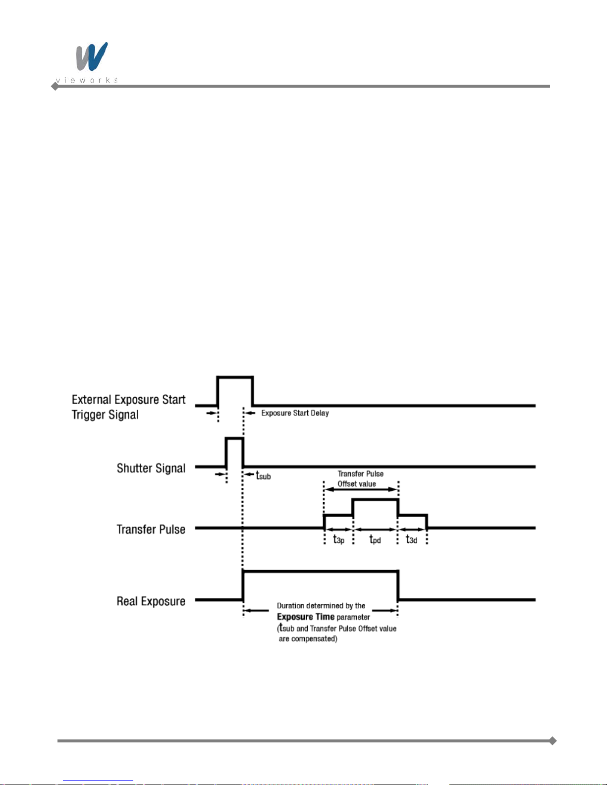
8.6 Real Exposure
8.6.1 Timed Exposure Mode
When the Timed mode is selected, the exposure time is determined by the time interval between the point
where an external trigger signal is applied and the point where the t
The camera generates a shutter signal to clear pixels when an external trigger signal is applied. The exposure
time begins when the shutter signal falls and continues until the t
8.9 shows, there is an Exposure Start Delay (refer to Table 8.3) between the rise of the external trigger signal
and the point where exposure actua l l y begins . The setting value on the Exposure Time parameter is equal to
the exposure time, because the t
compensated on the expos ure tim e by the camera’s logic internally. Therefore, there is no difference between
the setting value on the Exposure Time parameter and the exposure time. The t
Offset value are determined by the CCD sensor used in the camera.
value of the shutter signal and Transfer Pulse Offset value (tpd, t3p) are
sub
(Photodiode Transfer) signal falls.
pd
(Photodiode Transfer) signal falls. As Figure
pd
value and Transfer Pulse
sub
Figure 8.9 Real Exposure with Timed Exposure Mode
44 of 99 RA14-131-003

VA GigE series
8.6.2 Trigger Width Exposure Mode
When the Trigger Width mode is selected, the exposure time is controlled by the external trigger signal.
The camera generates a shutter signal to clear pixels when an external trigger signal is applied. The exposure
time begins when the shutter signal falls and continues until the tpd (Photodiode Transfer) signal falls. As Figure
8.10 shows, there is an Exposure Start Delay (refer to
Table 8.3) between the rise of the external trigger signal
and the rise of the shutter signal. There is difference between the width of the external trigger signal and the
exposure time as much as the t
value of the shutter signal and Transfer Pulse Offset value (tpd, t3p).
sub
You can calculate an actual exposure time by using the following formula:
Exposure Time = Trigger Width + t
+ tpd - t
3p
sub
Figure 8.10 Real Exposure with Trigger Width Exposure Mode
45 of 99 RA14-131-003

VA GigE series
t
sub
t3p
tpd
t3d
The t
The following table shows the t
and Transfer Pulse Offset value are determined by the CCD sensor used in the camera.
sub
and Transfer Pulse Offset values for VA GigE series.
sub
Real Exposure Parameters
Model
Exposure Start Delay
VA-1MG2
- -
1 ㎲ 5 ㎲ 1 ㎲
VA-2MG2
VA-4MG2
- -
- -
1 ㎲ 5 ㎲ 2 ㎲
VA-8MG2 - -
VA-29MG2
3 ㎲ 11 ㎲ 8 ㎲
- -
Table 8.2 Real Exposure Parameters
Remarks
t
t
: Shutter Transfer
sub
: VCCD leading pedestal
3p
signal
t
t
: Photodiode transfer signal
pd
: VCCD trailing pedestal
3d
signal
Exposure Start Delay: Trigger
Latency + Trigger Jitter
46 of 99 RA14-131-003

VA GigE series
8.7 Acquisition Timing Chart
Figure 8.11 shows a timing chart for frame acquisition and transmission. The chart assumes that exposure is
triggered by an externally generated exposure start trigger signal, that the Trigger A ctivation parameter is set to
Rising Edge and that the Exposure Mode parameter is set to Timed.
As shown in the figure below, there is a slight delay between the rise of the exposure start trigger signal and the
start of exposure. After the exposure time for a frame acquisition is complete, the camera begins reading out the
acquired frame data from the imaging sensor into a frame buffer in the camera. When a sufficient amount of
frame data has accumulated in the frame buffer, the camera will begin transmitting the data to your computer.
This buffering technique avoids the need to exactly synchronize the clock used for sensor readout with the data
transmission. The camera will begin transmitting data when it has determined that it can safely do so without
over-running or under-running the buffer.
Exposure Start Delay: the amount of time (including trigger jitter and latency) between the point
where the trigger signal rises and the point where exposure actually begins
Frame Readout time: the amount of time it takes to read out the frame data from the imaging
sensor into the frame buffer
Frame Transmission time: the amount of time it takes to transmit an acquired frame data from the
frame buffer in the camera to your computer
Transmission Start Delay: the amount of time between the point where the camera begins reading out
the acquired frame data from the sensor and the point where it begins transmitting the acquired frame data
from the buffer to your computer
Figure 8.11 Timing Chart (not drawn to scale)
47 of 99 RA14-131-003

VA GigE series
7.0 ㎲ ≤ Delay ≤ 19.2 ㎲ (2 Tap)
5.0 ㎲ ≤ Delay ≤ 16.2 ㎲ (2 T ap)
7.0 ㎲ ≤ Delay ≤ 25.2 ㎲ (2 T ap)
5.0 ㎲ ≤ Delay ≤ 22.2 ㎲ (2 T ap)
7.0 ㎲ ≤ Delay ≤ 28.4 ㎲ (2 T ap)
5.0 ㎲ ≤ Delay ≤ 25.4 ㎲ (2 T ap)
8.5 ㎲ ≤ Delay ≤ 35.8 ㎲ (2 T ap)
6.5 ㎲ ≤ Delay ≤ 32.8 ㎲ (2 T ap)
8.5 ㎲ ≤ Delay ≤ 45.4 ㎲ (2 T ap)
6.5 ㎲ ≤ Delay ≤ 42.4 ㎲ (2 T ap)
19.5 ㎲ ≤ Delay ≤ 115.8 ㎲ (2 Tap)
17.5 ㎲ ≤ Delay ≤ 112.8 ㎲ (2 Tap)
The following table shows Exposure Start Delay for VA GigE series.
Exposure Start Delay
Model
Exposure
Mode
Triggering during the Idle State Triggering during the Readout State
VA-1MG2
VA-2MG2
VA-2MG2
(HD)
VA-4MG2
VA-8MG2
Timed
Trigger Width
Timed
Trigger Width
Timed
Trigger Width
Timed
Trigger Width
Timed
Trigger Width
5 ㎲ ± 0.5 ㎲
2.5 ㎲ ± 0.02 ㎲
5 ㎲ ± 0.5 ㎲
2.5 ㎲ ± 0.02 ㎲
5 ㎲ ± 0.5 ㎲
2.5 ㎲ ± 0.02 ㎲
5 ㎲ ± 0.5 ㎲
2.5 ㎲ ± 0.02 ㎲
5 ㎲ ± 0.5 ㎲
2.5 ㎲ ± 0.02 ㎲
7.0 ㎲ ≤ Delay ≤ 30.0 ㎲ (1 T ap)
5.0 ㎲ ≤ Delay ≤ 27.0 ㎲ (1 T ap)
7.0 ㎲ ≤ Delay ≤ 42.0 ㎲ (1 T ap)
5.0 ㎲ ≤ Delay ≤ 39.0 ㎲ (1 T ap)
7.0 ㎲ ≤ Delay ≤ 48.4 ㎲ (1 T ap)
5.0 ㎲ ≤ Delay ≤ 45.4 ㎲ (1 T ap)
8.5 ㎲ ≤ Delay ≤ 59.8 ㎲ (1 T ap)
6.5 ㎲ ≤ Delay ≤ 56.8 ㎲ (1 T ap)
8.5 ㎲ ≤ Delay ≤ 79.0 ㎲ (1 T ap)
6.5 ㎲ ≤ Delay ≤ 76.0 ㎲ (1 T ap)
Timed
VA-29MG2
Trigger Width
1 horizontal line time(based on the Pixel Clock 50 ㎒ for VA-1/2/4/8M and Pixel Clock 40 ㎒ for VA-29M)
The exposure must always begin on an interline boundary of the CCD sensor. For this
reason, if a trigger signal is applied during the readout process, there might be an Exposure
Start Delay up to 1 horizontal line time.
The transmission time can vary due to the characteristics of the Ethernet network.
And also, the transmission start delay can vary from frame to frame; however, it is very low significance when
compared to the transmission time.
48 of 99 RA14-131-003
7 ㎲ ± 0.5 ㎲
4.5 ㎲ ± 0.02 ㎲
19.5 ㎲ ≤ Delay ≤ 198.9 ㎲ (1 Tap)
17.5 ㎲ ≤ Delay ≤ 195.9 ㎲ (1 Tap)
Table 8.3 Exposure Start Delay

VA GigE series
8.8 Maximum Allowed Frame Rate
In general, the maximum allowed acquisition frame rate on the camera may be limited by several factors:
The amount of time that it takes to transmit an acquired frame from the camera to your computer.
The amount of time needed to transmit a frame depends on the bandwidth assigned to the camera.
The setting for the Sensor Digitization Taps parameter. If this parameter is set for Two taps, you will be
able to acquire frames at a higher rate than if it is set to One tap.
The Binning feature. If binning is enabled, the maximum allowed frame rate will increase.
The amount of time it takes to read an acquired frame out of the imaging sensor and into the camera’s
frame buffer. This time varies depending on the setting for the Height parameter. Frames with a smaller
height take less time to read out of the sensor. The frame height is determined by the camera’s Height
settings (Image Format Control).
The exposure time for acquired frames. If you use very long exposure times, you can acquire fewer frames
per second.
Decreasing the Height parameter can increase the maximum allowed frame rate; however
the Width parameter does not affect the frame rate.
When the camera's Acquisition Mode is set to Single Frame, the maximum possible
acquisition frame rate for a given ROI cannot be achieved. This is true because the camera
performs a complete internal setup cycle for each single frame and because it cannot be
operated with Trigger Overlap – Readout mode.
To achieve the maximum possible acquisition frame rate, set the Acquisition Mode
parameter to Continuous and the Trigger Overlap parameter to Readout.
49 of 99 RA14-131-003

VA GigE series
8.8.1 Increasing the Maxim um Allowed Frame Rate
You may find that you would like to acquire frames at a rate higher than the maximum allowed with the camera’s
current settings. In this case, you must adjust one or more of the factors that can influence the maximum allowed
frame rate and then check to see if the maximum allowed frame rate has increased:
The time that it takes to transmit a frame out of the camera is the main limiting factor on the frame rate. You
can decrease the frame transmission time (and thus increase the maximum allowed frame rate) by doing
one or more of the following:
Use an 8 bit pixel data format rather than a 12 bit pixel format. Images with fewer bits per pixel will take
less time to transmit.
Use a smaller ROI. Decreasing the ROI means that the camera has less data to transmit and therefore
the transmission time will decrease.
Use binning. When pixels are binned, there is less data to transmit and therefore the transmission time
will decrease.
Make sure that the Packet Size (GevSCPSPacketSize) parameter is set as high as possible for your
system and that the Inter-Packet delay (GevSCPD) parameter is set as low as possible.
If you have the Sensor Digitization Taps parameter set to One, consider changing the value to Two. This
will usually increase the maximum allowed frame rate.
If you are using normal exposure times and you are using the camera at its maximum resolution, your
exposure time will not normally restrict the frame rate. However, if you are using long exposure times or
small region of interest, it is possible that your exposure time is limiting the maximum allowed frame rate. If
you are using a long exposure time or a small ROI, try using a shorter exposure time and see if the
maximum allowed frame rate increases. (You may need to compensate for a lower exposure time by using a
brighter light source or increasing the opening of your lens aperture.)
An important thing to keep in mind is a common mistake new camera users frequently make
when they are working with exposure time. They will often use a very long expos u r e tim e
without realizing that this can severely limit the camera’s maximum allowed frame rate. As an
example, assume that your camera is set to use a 1 second exposure time. In this case,
because each frame acquisition will take at least 1 second to be completed, the camera will
only be able to acquire a maximum of one frame per second. Even if the camera’s nominal
maximum frame rate is, for example, 2 frames per second, it will only be able to acquire one
frame per second because the exposure time is set much higher than normal.
50 of 99 RA14-131-003

VA GigE series
9 Camera Features
9.1 Image Region of Interest
The Image Region of Interest (ROI) feature allows you to specify a portion of the sensor array. You can acquire
only the frame data from the specified portion of the sensor array while preserving the same quality as you
acquire a frame from the entire sensor array. With the ROI feature, you can achieve increased frame rates by
decreasing the height of the ROI; however, decreasing the width of the ROI does not affect the frame rate.
The ROI is referenced to the top left corner [origin (0, 0)] of the sensor array as follows.
51 of 99 RA14-131-003
Figure 9.1 Image Region of Interest

VA GigE series
The XML parameters related to ROI settings are as follows.
XML Parameters Value Description
SensorWidth
a
- Effective width of the sensor
SensorHeighta - Effective height of the sensor
WidthMaxb
camera settings
Maximum allowed height of the image with the
Maximum allowed width of the image with the current
ImageFormatControl
HeightMaxb -
current camera settings
Widthc - Current width of the image
Heightc - Current height of the image
OffsetX
OffsetY
b, d
- Horizontal offset from the origin to the Image ROI
b, d
- Vertical offset from the origin to the Image ROI
The unit for all parameters in this table is pixel
a: Read only. User cannot change the value
b: Changes and updates according to the Binning settings
c: User configurable parameters for settings ROI
d: User configurable parameters for setting the origin of the ROI
Table 9.1 XML parameters related to ROI
You can change the size of ROI by setting the Width and Height parameters. And a lso, you can change the
position of the ROI origin by setting the Offset X and Offset Y parameters.
Make sure that the Width + Offset X value is less than the Width Max value, and the Height + Offset Y value is
less than the Height Max value. You must set the s ize of the ROI f irst, and then set the Offset values since the
Width and Height parameters are set to its maximum value by default.
The Width parameter m ust be set to a m ultiple of 4, and the He ight parameter must be set to a value greater
than the minimum Vertical ROI size shown in the
changed and updated depending on the Binning Horizontal and Binning Vertical parameter settings
respectively. And also, the Width, Height, Offset X and Offset Y parameter s will be u pdated depen ding on the
Binning Horizontal and Binning Vertical parameter settings respectively.
ROI Size updated according to the Binning settings may not be restored to its original value. For example, if you
set the Binning Horizontal parameter to
automatically. Then, if you set the Width parameter to 166 and the Binning Horizontal parameter to
Width parameter will be 498 (166 × 3). If you want to restore the Width to its original value, you can set the
Width to 500 manually.
52 of 99 RA14-131-003
table 9.2. The Width Max and Height Max parameters will be
×3 with 500 Width, the Width parameter will be updated to 166
×1, the

VA GigE series
The approximate maximum frame rate depending on the change of Vertical ROI can be obtained as shown in the
following expression.
1 or 2 Channel Mode:
Frame Rate (fps) = 1000000 / [T
T
: the amount of time required to transmit electric charges accumulated on
VCCD
+ TRF × {V
VCCD
SIZE
– (V
+ 12)} + (V
ROI
the pixels to Vertical Register
TRF : the amount of time required for 1 row flush
V
: the number of Vertical Line of CCD
SIZE
TL : the amount of time required for transmission of one line
V
: size of the Vertical ROI
ROI
The available minimum value of T
The value of T
may vary depending on the Sensor Digitization Taps and Pclk Selector parameter settings.
L
VCCD
, TRF, V
, TL and V
SIZE
may vary depending on the camera model.
ROI
The values of each item are shown below.
VA GigE Series
T
VCCD
TL (1 channel)
TL (2 channel)
VA-1MG† VA-2MG† VA-2M(HD)† VA-4MG† VA-8MG† VA-29MG‡
12 ㎲ 12 ㎲ 12 ㎲ 15.0 ㎲ 15.0 ㎲ 51 ㎲
24 ㎲ 36 ㎲ 42.4 ㎲ 52.3 ㎲ 71.5 ㎲ 182.4 ㎲
13.2 ㎲ 19.2 ㎲ 22.4 ㎲ 28.3 ㎲ 37.9 ㎲ 99.3 ㎲
+ 12) × TL]
ROI
TRF TL * 0.28 TL * 0.28 TL * 0.28
V
1064 Lines 1264 Lines 1144 Lines 1800 Lines 2520 Lines 4452 Lines
SIZE
4.0 ㎲ 4.0 ㎲ 16.0 ㎲
Minimum
Vertical ROI
120 Lines 150 Lines 120 Lines 200 Lines 300 Lines 500 Lines
Size
† Based on Pixel Clock 50 ㎒ (PclkSelector: PCLK1 for VA-1/2/4/8MG)
‡ Based on Pixel Clock 40 ㎒ (PclkSelector: PCLK1 for VA-29MG)
Table 9.2 T iming Value for VA GigE Series
53 of 99 RA14-131-003

VA GigE series
The following figure shows frame rate for each camera model depending on Vertical ROI changes with 1 Tap and
2 T ap settings.
Figure 9.2 Frame Rate by Vertical ROI changes
54 of 99 RA14-131-003

VA GigE series
9.2 Binning
Binning has the effects of increasing the level value and decreasing resolution by summing the values of the
adjacent pixels and sending them as one pixel.
The XML parameters related to Binning are as follows.
XML Parameters Value Description
BinningHorizontal
×1, ×2, ×3,
×4, ×8
ImageFormatControl
×1, ×2, ×3,
BinningVertical
×4, ×8
Table 9.3 XML Parameters related to Binning
For example, if you set 2 × 2 binning as shown in the figure below, four pixels will be summed into one pixel.
Then, the effective maximum resolution of the sensor is reduced to 1/2. The Width Max and Height Max
parameters, indicating the maximum allowed resolution of the image with the current camera settings, will be
updated depending on the binning settings. And also, the Width, Height, Offset X and Offset Y parameters will
be updated depending on the binning settings. You can verify the current resolution through the Width and
Height parameters.
Since vertical binning is processed in the internal register of CCD, the frame rate will be increased and SNR will
be improved because the number of the readout process is reduced. However, the horizontal binning does not
affect the frame rate and SNR because it is processed in the FPGA. The brightness will be increased about four
times because four pixels are summed as one.
Number of horizontal pixels to combine
together
Number of vertical pixels to combine together
55 of 99 RA14-131-003
Figure 9.3 Binning

VA GigE series
VA GigE series supports ×1, ×2, ×3, ×4, ×8 binning factors for both ver t ical and hor izo ntal direc tio n
independently.
Figure 9.4 Binning factors
Even if the binning is performed on the color camera, the resulting image will be
monochrome.
The odd number of binning factor (×3) does not supported on the color camera due to
the characteristics of Bayer pattern.
56 of 99 RA14-131-003

VA GigE series
Active Pixels
B
G
G
R
B
G
G
R
B
G
G
R
B
G
G
R
B
G
G
R
B
G
G
R
B
G
G
R
B
G
G
R
Left Dark Columns
Two Taps
Right Dark Columns
Top Dark Rows
Bottom Buffer Rows
Top Buffer Rows
Left Buffer Columns
Right Buffer Columns
One Tap
Video L Video R
Left Dummy Pixels
Rigth Dummy Pixels
Horizontal Register
Bottom Dark Rows
(1, 1)
9.3 Sensor Tap Settings
With two taps sensor digitization, two (left and right) video amplifiers are used to output the charges moved to
the horizontal register during reading out the accumulated charges. Charges from the left half of the sensor are
shifted towards the Video L and charges from the right half of the sensor are shifted towards Video R.
Figure 9.5 Two Taps Sensor Digitization
57 of 99 RA14-131-003

VA GigE series
ADC
CCD
Video L
FPGA
Image
Processing
&
Reorder
LVDS
GigE
Frame
Buffer
ADC
ADC
CCD
Video L
Video R
FPGA
Image
Processing
&
Reorder
LVDS
GigE
Frame
Buffer
LVDS
XML parameters related to Sensor Tap Settings are as follows.
XML Parameters Value Description
ImageFormatControl SensorDigitizationTaps
Table 9.4 XML Parameter related to Sensor Tap Settings
When you set the Sensor Digitization Taps parameter to One, only the left video amplifier (Video L) will be
used to output the video data as shown in the Figure 9.6. And when you set the Sensor Digitization Taps
parameter to Two, both Video L and Video R will be used to output the video data as shown in the Figure 9.7.
When LVDS signals converted from the video data through ADC are transmitted to FPGA, the signal data will be
stored in the line buffer of FPGA until the transmission of one hor i zontal line is completed. Figure 9.8 and 9.9
show the structure which reorders and stores one line video data in the line buffer of FPGA according to the one
tap and two taps settings. After c om pleti ng o ne line transmission, the data goes t hrough image processing. Then,
the data will be reordered according to the Pixel Format parameter setting value and stored in the frame buffer.
One S et the Sensor Readout mode to 1 tap
Two Set the Sensor Readout mode to 2 tap
58 of 99 RA14-131-003
Figure 9.6 1Tap Image Data Flow
Figure 9.7 2Taps Image Data Flow

VA GigE series
14-bit
Video L(N)
1 Line Buffer
14-bit
14-bit
Video L(N+1) Video L(N+2)
14-bit
Video L
1 Line Buffer
14-bit
Video R
D11 D10 D9 D8 D7 D6 D5 D4 D3 D2 D1 D0
D11 D10 D9 D8 D7 D6 D5 D4 D3 D2 D1 D0
D12D13
MSB LSB
Figure 9.8 1 Tap Reorder
Figure 9.9 2 Tap Reorder
The LVDS video data converted in ADC are 14 bits, however the camera outputs 12 bits video data. The noise
performance will be improved on the output image by removing the 2 least significant bits.
Figure 9.10 12bit Conversion
59 of 99 RA14-131-003

VA GigE series
D11
D
10 D
9 D
8
D7 D6 D5
D4
D
3 D
2 D
1
D0
MSB
LSB
12
Bit Output
10Bit Output
8Bit Output
D
9 D8 D7 D
6 D5
D4 D
3 D2 D1 D
0
D11
D
10 D9
D8 D
7 D6
D5 D
4
D
3 D2
D1 D0
D
7 D6 D5 D4
D3 D
2 D1
D0
Original
Data
9.4 Pixel Format
The internal processing of image data is performed in 12 bits. Then, the camera can output the data in 8, 10 or
12 bits. When the camera outputs the image data in 8 bits or 10 bits, the 4 or 2 least significant bits will be
truncated accordingly.
Figure 9.11 Pixel Format
The image data converted to 8, 10 or 12 bits support various pixel data format depending on the camera model.
The pixel data will be reordered in FPGA according to the Pixel Format se tti ng va lue. Then, it will be stored in
the frame buffer before output. XML parameter related to the Pixel Format is as follows.
XML Parameters Description
ImageFormatControl PixelFormat Set the pixel format supported by the device
Table 9.5 XML Parameter related to Pixel Format
60 of 99 RA14-131-003

VA GigE series
7 6 5 4 3 2 1 0
8-bit
Pixel Data
Byte 0
MSB LSB
The supported pixel formats for monochrome and color cameras are as follows.
Mono Sensor Color Sensor
Mono 8
Mono 10
Mono 10 Packed
Mono 12
Mono 12 Packed
Table 9.6 Pixel Data Format Value
The structures for supported pixel formats are as follows.
Mono 8
Mono 10
Mono 10 Packed
Mono 12
Mono 12 Packed
Bayer GR 8
Bayer GR 10
Bayer GR 12
Bayer GR 10 Packed
Bayer GR 12 Packed
Mono 8
With the camera set to Mono 8, the pixel data output is 8 bit monochrome, unsigned char and unpacked type.
This type is stored in a byte unit when 8 bit pixel data are stored in the frame buffer.
Figure 9.12 Mono 8 Format
61 of 99 RA14-131-003

VA GigE series
8-bit
2-bit
Pixel Data
Byte 1 Byte 0
LSBMSB
7 6 5 4 3 2 1 0
9 8
X X X X X X
8-bit
Pixel Data 1
Byte 2 Byte 1
LSBMSB
Byte 0
Pixel Data 0
8-bit
2-bit
9 8 7 6 5 4 3 2
1 0
9 8 7 6 5 4 3 2
2-bit
1 0
X X X X
Mono 10
With the camera set to Mono 10, the pixel data output is 10 bit monochrome, unsigned char and unpacked type.
This type is divided into two bytes when 10 bit pixel data are stored in the frame buffer. 8 bits of pixel data will be
stored in Byte 0, 2 bits of pixel data will be stored in Byte 1, and the rest 6 bits will not be used.
Figure 9.13 Mono 10 Format
Mono 10 Packed
With the camera set to Mono 10 Packed, the pixel data output is 10 bit monochrome, unsigned char and
GigE Vision-specific packed type.
This type is divided into three bytes when 20 bit pixel data are stored in the frame buffer. 8 bits of pixel data 0 will
be stored in Byte 0 and the rest 2 bits will be stored in Byte 1. Pixel Data 1 will be stored in Byte 2 and the rest 2
bits will be stored in Byte 1.
Figure 9.14 Mono 10 Packed Format
62 of 99 RA14-131-003

VA GigE series
8-bit
4-bit
Pixel Data
Byte 1 Byte 0
LSBMSB
7 6 5 4 3 2 1 0
11 10 9 8
X X X X
8-bit
Pixel Data 1
Byte 2 Byte 1
LSB
Byte 0
4-bit
Pixel Data 0
8-bit
4-bit
11 10 9 8 7 6 5 4
3 2 1 0 3 2 1 0
11 10 9 8 7 6 5 4
Mono 12
With the camera set to Mono 12, the pixel data output is 12 bit monochrome, unsigned and unpacked type.
This type is divided into two bytes when 12 bit pixel data are stored in the frame buffer. 8 bits of pixel data will be
stored in Byte 0 and the rest 4 bits will be stored in Byte 1. The rest 4 bits of Byte 1 will not be used.
Figure 9.15 Mono 12 Format
Mono 12 Packed
With the camera set to Mono 12 Packed, the pixel data output is 12 bit monochrome, unsigned and
GigE Vision-specific packed type.
This type will be divided into three bytes when 24 bit pixel data are stored in the frame buffer.
8 bits of pixel data 0 will be stored in Byte 0 and the rest 4 bits will be stored in Byte 1. 8 bits of pixel data 1 will
be stored in Byte 2 and the rest 4 bits will be stored in Byte 1.
Figure 9.16 Mono 12 Packed Format
63 of 99 RA14-131-003

VA GigE series
8
-bit
Pixel Data
(2
,
1)
-Red
Byte
2 Byte 1
LSBMSB
Byte 0
2-
bit
Pixel Data
(1
,1)-Green
8-bit
2
-bit
9 8 7 6 5 4 3 2
X X
1 0 X X
1 0
9 8 7 6 5 4 3 2
8-bit
Byte
2 Byte 1
LSB
MSB
Byte 0
2-
bit8-
bit
2-bit
9 8 7 6 5 4 3 2
X X 1 0 X X 1 0
9 8 7 6 5 4 3 2
Horizontal
Direction
Vertical
Direction
1
-Line
2-Line
Pixel Data (
0,1)
-Green Pixel Data
(1,
2)-
Blue
Bayer Format
When you set the Pixel Format parameter to any Bayer Format in the color camera, the bits of pixel data will
be reordered to bytes, and then will be stored in the frame buffer in the same way as Mono Format.
For example, if you set the Pixel Format parameter to Bayer GR 10 Packed, the pixel data will be reordered
and stored in the frame buffer as shown in the Figure 9.21. 10 least significant bits of green data will be stored in
Byte 0 and Byte 1, and 10 most significant bits of red data will be stored in Byte 2 and Byte 1. The bit order is
shown in the first figure below. After saving 1 - horizontal line of G-R pattern pixel data, 2 – horizontal line of B-G
pattern pixel data will be stored as shown in the second figure below. G-R pattern (Horizontal Direction) and B-G
pattern (Horizontal Direction) pixel data will be stored repeatedly as a line (Vertical Direction).
64 of 99 RA14-131-003
Figure 9.17 Bayer Format

VA GigE series
9.5 Pixel Clock
VA GigE camera provides a unique way to control the camera speed and frame rate. You can select the pixel
clock to operate the camera either in Normal or High-speed (over-clocked) mode. With Normal mode, the
camera’s frame rate is determined by the CCD sensor manufacturer.
VA GigE camera internal design is optimized for High-speed mode. With High-speed mode, it is possible to overclock the camera which will result in higher frame rate. However, the camera signal to noise ratio (SNR) may be
reduced compared to Normal mode.
XML parameters related to pixel clock are as follows.
XML Parameters Value Description
PCLK0 Set pixel clock to Normal mode
VA-1/2/4/8MG2 - 40 ㎒
DeviceControl
PclkSelector
PCLK1 Set pixel clock to High-speed mode
CurrentPclkFreq -
Table 9.7 XML Parameters related to Pixel Clock
VA-29MG2 - 30 ㎒
VA-1/2/4/8MG2 - 50 ㎒
VA-29MG2 - 40 ㎒
Display the current camera pixel clock in ㎒
65 of 99 RA14-131-003

VA GigE series
9.6 Stream Hold
VA GigE camera provides Stream Hold feature for controlling the transmission of data.
Normally, the camera transmits frame data to the host computer immediately after completing the exposure.
Enabling the Stream Hold feature delays the transmission of data, storing it in the camera’s volatile memory
until the Stream Hold feature is disabled.
This feature is especially useful to prevent flooding in Gigabit Ethernet network where multiple cameras are
connected to a single host computer and capture a single event. Using the Stream Hold feature, each camera
will hold the image data until the camera’s Stream Hold feature is disabled. VA GigE camera provides 128 MB
on-board memory for the Stream Hold feature. The Stream Hold feature does not allow you to select which
frame will be released to the host computer. When the Stream Hold feature is disabled, the stored frame data
will be released to the host computer. For more information, refer to the application note about stream hold.
XML Parameters Value Description
On Delay the transmission of frame data and store them
TransportLayerControl
StreamHold
Off
- Display the maximum number of frames that you
FrameCapacity
Table 9.8 XML Parameters related to Stream Hold feature
in the frame buffer.
Release the stored frame data to the host computer.
can store in the frame buffer
The maximum number of frames will vary
depending on the Image ROI and pixel format
settings.
With the Stream Hold feature set to On, the
newly acquired frame will be ignored after saving
the maximum number of frames.
66 of 99 RA14-131-003

VA GigE series
9.7 Inter-Packet Delay
VA GigE camera provides the Inter-packet delay feature to set the delay in ticks between the packets transmitted
by the camera.
Packet Size
The Gev SCPS Packet Size parameter sets the size of the packets that the camera will use when it sends the
data via the selected stream channel. This parameter should always be set to the maximum size that your
network components (Ethernet Adapter) can handle.
Setting the delay between packets
The Gev SCPD parameter sets the delay in ticks between the packets transmitted from the camera. Increasing
the delay will decrease the camera’s effective data transmission rate and will thus decrease the network
bandwidth used by the camera.
In the VA GigE camera, one tick is 8 ㎱. To check the tick frequency, read the Gev Time stamp Tick Frequency
parameter value.
In case of multiple cameras or other devices working on the same physical network, it might be desirable to send
the packets of a camera’s streaming channel with a certain inter-packet delay in order to allow multiple cameras
or devices to share a given network bandwidth.
XML Parameters Value Description
Set the packet size (The maximum
TransportLayerControl
GevSCPSPacketSize 576~16,000 Bytes
GevSCPD
Table 9.9 XML Parameters related to Inter-Packet Delay
0~ TBD
value may vary depending on the
Ethernet Adapter.).
Set the delay between packets.
67 of 99 RA14-131-003

VA GigE series
9.8 Data ROI (Color Cameras)
The Balance White Auto features use the pixel data from a Data Region of Interest (ROI) to adjust the related
parameters. XML parameters related to data ROI are as follows.
XML Parameters Value Description
RoiSelector AWB Select a Data ROI used for Balance White Auto
RoiOffsetX - X coordinate of start point ROI
DataRoiControl
RoiOffsetY - Y coordinate of start point ROI
RoiWidth - Width of ROI
RoiHeight - Height of ROI
Table 9.10 XML Parameters related to Data ROI
68 of 99 RA14-131-003

VA GigE series
Only the pixel data from the area of overlap between the data ROI by your settings and the Image ROI will be
effective if you use Image ROI and Data ROI at the same time. The effective ROI is determined as shown in the
figure below.
69 of 99 RA14-131-003
Figure 9.18 Effective Data ROI

VA GigE series
9.9 Balance White Auto (Color Cameras)
The Balance White Auto feature is implemented on color cameras. It will control the white balance of the image
acquired from the color camera according to the GeryWorld algorithm. Before using the Balance White Auto
feature, you need to set the Data ROI for Balance White Auto. If you do not set the related Data ROI, the pixel
data from the Image ROI will be used to control the white balance. As soon as the Balance White Auto
parameter is set to Once, the Digital Red, Digital Green and Digital Blue will be set to 1. Then, Digital Red and
Digital Blue will be adjusted to control the white balance.
XML parameters related to the Balance White Auto and RGB Gain settings are as follows.
XML Parameters Value Description
AnalogAll Apply gain to all analog taps
AnalogTap1 Apply analog gain to Tap1
AnalogControl
GainSelector
Gain
BalanceWhiteAuto
Table 9.11 XML Parameters related to Balance White Auto
AnalogTap2 Apply analog gain to Tap2
DigitalRed Apply gain to red digital channel
DigitalGreen Apply gain to green digital channel
DigitalBlue Apply gain to blue digital channel
Set an absolute physical gain value when Digital
×0.5 ~ ×2.0
Red, Green or Blue is selected
Off Balance White Auto Off
Once White Balance is adjusted once and then Off
70 of 99 RA14-131-003

VA GigE series
CDS
GAIN
VGA
GAIN
ANALOG
CCD IN
LEVEL
CLAMP
14
-BIT
LVDS
1~
40 times
14-BIT
ADC
9.10 Gain and Black Level
You can set the analog (VGA) and digital gain factor to adjust the gain. The black level is adjusted by removing
the optical black offset from the CCD so that the effect of dark current will be minimized.
9.10.1 Analog Domain
The VA GigE camera has one Analog Signal Processor (or Analog Front End (AFE)) for each channel. This AFE
consists of Correlated Double Sampler (CDS), Variable Gain Amplifier (VGA), Black Level Clamp and 14-bit A/D
converter.
You can change the gain and black level value by inputting proper value into the registers for gain and black
level adjustments inside the AFE. The CDS gain value is set in the factory during the manufacturing process,
therefore you cannot change the value. The VGA gain is the same as the analog gain. You can set the analog
gain for all analog taps or each tap. You can determine whether to control the gain balance between each tap
manually or automatically by setting the Gain Auto Balance parameter to Off or Once. To balance the black
level between each tap, use the Black Level parameter.
71 of 99 RA14-131-003
Figure 9.19 AFE Block Diagram

VA GigE series
then Off
9.10.2 Digital Domain
VA GigE camera has a built in digital gain and black level control. XML parameters related to Gain and Black
Level are as follows.
XML Parameters Value Description
AnalogAll Apply gain to all analog taps
AnalogTap1 Apply analog gain to Tap1
GainSelector
Gain -
AnalogControl
GainAutoBalance
BlackLevelSelector
BlackLevel 0~255
†: Adjustable value range when the Gain Selector parameter is set to Analog All and the Gain parameter
AnalogTap2 Apply analog gain to Tap2
DigitalRed Apply gain to red digital channel
DigitalGreen Apply gain to green digital channel
DigitalBlue Apply gain to blue digital channel
Set an absolute physical gain value.
Analog All: ×1.0 ~ ×40
Analog T ap1, 2: ×0.96 ~ ×65†
Off Gain Auto Balance Off
Once
All Apply black level to all taps
Tap1 Apply black level to Tap1
Tap2 Apply black level to Tap2
Gain Balance for each tap is adjusted once‡ and
Set an absolute physical black level value.
(0 ~ 127 LSB @ 12bit)
is set to 1. The adjustable value range may vary depending on the Gain setting value for Analog All.
‡: The illumination must be of uniform intensity throughout the sensor when performing Gain Auto Balance.
Table 9.12 XML Parameters related to Gain and Black Level
72 of 99 RA14-131-003

VA GigE series
12-bit Data
4096 entry
Lookup Table
12-bit Data
LUT
0
500
1000
1500
2000
2500
3000
3500
4000
0 500 1000 1500 2000 2500 3000 3500 4000
Input Level
Output Level
9.11 LUT
LUT (Lookup Table) converts original image values to certain level values.
Luminance
Since it is mapped one to one for each level value, 12-bit output can be connected to 12-bit input. LUT is in the
form of table that has 4096 entries between 0~4095 and VA GigE camera provides a non-volatile space for LUT
data storage. You can determine whether to apply LUT and which LUT to use. For more information about how
to download LUT to the camera, refer to
Appendix B.
Figure 9.20 LUT Block
73 of 99 RA14-131-003
Figure 9.21 LUT at Gamma 0.5

VA GigE series
XML parameters related to LUT are as follows.
XML Parameters Value Description
LUTSelector Luminance Luminance LUT
LUTControl
LUTEnable
On Activate the selected LUT
Off Deactivate the selected LUT
Index of coefficient for verifying the LUT Value
LUTIndex -
Luminance: 0 ~ 4095
Output value of the current LUT corresponding to the input value
LUTValue -
of LUT Index
Table 9.13 XML Parameters related to LUT
74 of 99 RA14-131-003

VA GigE series
L3 L
2 L
1 R1
R2 R
3
<Current Pixel
>
9.12 Defective Pixel Correction
The CCD may have Defective Pixels which cannot properly react to the light. Correction is required since it may
deteriorate the quality of output image. Defective Pixel information of CCD used for each camera is entered into
the camera during the manufacturing process in the factory. If you want to add Defective Pixel information, it is
required to enter coordinate of new Defective Pixel into the camera.
9.12.1 Correction Method
Correction value for a defective pixel is calculated based on valid pixel value adjacent in the same line.
Figure 9.22 Location of Defective Pixel to be corrected
If current pixel is a defective pixel as shown in the above figure, correction value for this pixel is obtained as
shown in the following table depending on whether surrounding pixel is defective pixel or not.
Adjacent Defective Pixel(s) Correction value of Current Pixel
None (L1 + R1) / 2
L1 R1
R1 L1
L1, R1 (L2 + R2 ) / 2
L1, R1, R2 L2
L2, L1, R1 R2
L2, L1, R1, R2 (L3 + R3) / 2
L2, L1, R1, R2, R3 L3
L3, L2, L1, R1, R2 R3
Table 9.14 Calculation of Defective Pixel Correction Value
75 of 99 RA14-131-003

VA GigE series
9.12.2 Correction Method in Binning Mode
When 2×2 or 4×4 binning is enabled, the defect correction feature is available. The correction value will be
averaged based on four neighboring pixels during 2×2 binning and sixteen neighboring pixels during 4×4
binning.
XML parameter related to Defective Pixel Correction is as follows.
XML Parameters Value Description
ImageFormatControl DefectivePixelCorrection
Table 9.15 XML Parameter related to Defective Pixel Correction
To apply the Defective Pixel Correction feature, you must download a Defective Pixel Map
to the camera. For more information about how to download a Defective Pixel Map to the
camera, refer to
Appendix A.
On
Apply a downloaded defective pixel map to
the camera
Disable the application of the defective pixel
Off
map
76 of 99 RA14-131-003
VA GigE series
9.13 Flat Field Correction
The Flat Field Correction feature improves the image uniformit y when you acquire a non-uniformity image due to
external conditions. The Flat Field Correction feature can be summarized by the following equation:
IC = {(IR – IB) × M} / (IF – IB)
Where,
IC : Level value of corrected image;
IR : Level value of original image;
IB : Black offset value;
M : Average value of image after correction;
IF : Level value of Flat Field data.
In actual use conditions, generate a Flat Field data (IF) and perform the Flat Field Correction feature according
to the following procedures.
1. Set the binning mode as desired.
2. Set the number of frames to be acquired for generating the Flat Field data into the Ffc Frames parameter.
3. Execute the Ffc Generate parameter. The series of frames will be averaged and scaled down to 1/16 pixel.
Then, the camera will generate the Flat Field data.
4. Execute the Ffc Save parameter to save the generated Flat Field data in the non-volatile memory.
When the Flat Field data are applied for correction, the Flat Field data which were scaled down will be
enlarged via Bilinear Interpolation as shown in the Figure 9.24.
5. Set the average value in the Ffc Target Level parameter and the Ffc Mode parameter to On. Then, the
Flat Field data will be applied to the camera.
Executing the Ffc Generate parameter will ignore the current camera settings and will
temporarily change the camera settings to operate under the following default conditions.
When the generation of the Flat Field data is completed, the original settings of the
camera will be restored. If the Trigger Mode parameter is set to On and the Trigger
Source parameter is set to Software, you must provide the number of trigger signals
equal to the current Acquisition Frame Count parameter setting.
Readout Mode: Normal
Trigger Mode: Free-Run
Channel Mode: Single
Defective Pixel Correction: ON
Every time you change the binning mode, you must generate the Flat Field data again.
77 of 99 RA14-131-003

VA GigE series
Scale Down
External
SDRAM
Bilinear
Interpolated
Magnification
External
SDRAM
IR*
M
/IF
<
IR
>
<IF
>
<
IC>
<Flat Fielding Block Diagram>
<Flat Field Calibration Block Diagram>
16 Pixel
16 Pixel
copycopy
copycopy
copy
copy
Scale-Down Data
Magnified Image
Boundary
Magnified Image
Boundary
78 of 99 RA14-131-003
Figure 9.23 Generation and Application of Flat Field Data
Figure 9.24 Bilinear Interpolated Magnification

VA GigE series
XML parameters related to Flat Field Correction are as follows.
XML Parameters Value Description
FlatFieldCorrection
FfcMode
Off Flat Field Correction Off
On†
Enable the Flat Field Correction feature
FfcTargetLevel 0~4095 Set the average grey level for image background
Set the number of frames to be acquired when
generating the Flat Field data. The more frames result
FfcFrames 1,2,4,8,16
in the better data; however it takes more time to
generate the data.
FfcGenerate - Generate the Flat Field data
Save the generated Flat Field data in the non-volatile
memory. The generated data by executing the
FfcGenerate parameter are saved in the volatile
FfcSave -
memory and the data are lost if the camera is reset or if
power is turned off. T o use the data after the camera is
powered on or reset, save them in the non-volatile
memory.
Load the Flat Field data from the non-volatile memory
FfcLoad -
into volatile memory
†: If the current setting values for the Binning Horizontal and Binning Vertical parameters are different from
the setting values at the time when you generate the Flat Field data, the Flat Field Correction feature is not
available even if you set the Ffc Mode parameter to On.
Table 9.16 XML Parameters related to Flat Field Correction
79 of 99 RA14-131-003

VA GigE series
9.14 Temperature Monitor
A sensor chip is embedded in the camera to monitor the internal temperature.
XML parameter related to Device Temperature is as follows.
XML Parameters Description
DeviceControl DeviceTemperature Display device temperature in Celsius
Table 9.17 XML Parameter related to Device Temperature
9.15 Fan Control (Only available on VA-29MG2)
A fan is installed on the rear panel of the camera to radiate heat. You can set the fan to turn on or off. And also,
you can set the fan to turn on when a specified internal temperature is reached.
XML parameters related to Fan Control are as follows.
XML Parameters Value Description
FanControl
Off Turn off the fan
On Turn on the fan
FanOperationMode
Temperature
FanOperationTemperature
FanSpeed - Verify the current Fan RPM
Table 9.18 XML Parameters related to Fan Control
-10℃~80℃
Turn on the fan when the internal temperature
exceeds the value set in the Fan Operation
Temperature parameter
Set the temperature to operate the fan w hen the
Fan Operation Mode parameter is set to
Temperature
80 of 99 RA14-131-003

VA GigE series
9.16 Status LED
A green LED is installed on the back panel of the camera to inform the operation status of the camera. LED
status and corresponding camera status are as follows:
Continuous ON: operates in Trigger Off Mode.
Repeat ON for 0.5 seconds, OFF for 0.5 seconds: operates in Trigger Mode.
Repeat ON for 1 second, OFF for 1 second: outputs T est Image.
Repeat ON for 0.25 second, OFF for 0.25 second: operates in Trigger Mode and outputs Test Image.
81 of 99 RA14-131-003
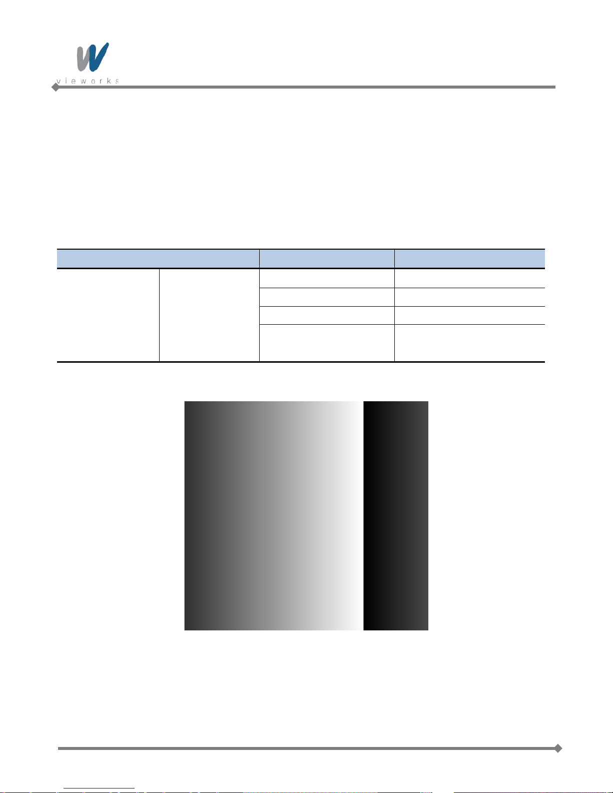
VA GigE series
9.17 Test Image
To check whether the camera operates normally or not, it can be set to output test images generated in the
camera, instead of the image data from the CCD. Three types of test images are available; image with different
value in horizontal direction (Grey Horizontal Ramp), image with different value in diagonal direction (Grey
Diagonal Ramp), and moving image with different value in diagonal direction (Grey Diagonal Ramp Moving).
XML parameters related to T est Image are as follows.
XML Parameters Value Description
Off Test Image Off
GreyHorizontalRamp Set to Grey Horizontal Ramp
ImageFormatControl TestImageSelector
Table 9.19 XML Parameter related to Test Image
GreyDiagonalRamp Set to Grey Diagonal Ramp
GreyDiagonalRampMoving Set to Grey Diagonal Ramp
Moving
82 of 99 RA14-131-003
Figure 9.25 Grey Horizontal Ramp

VA GigE series
Figure 9.26 Grey Diagonal Ramp
Figure 9.27 Grey Diagonal Ramp Moving
The test image may look different because the region of the test image may vary depending
on the camera’s resolution.
83 of 99 RA14-131-003

VA GigE series
9.18 Reverse X
The Reverse X feature let you flip the image horizontally. This feature is available in all operation modes.
Figure 9.28 Original Image
On color models of the camera, when the Pixel Format parameter is set to Bayer and the
Reverse X feature is used, the alignment of the color filter will be changed.
84 of 99 RA14-131-003
Figure 9.29 Reverse X Image

VA GigE series
9.19 Digital IO Control
The pin number 3 of the control receptacle is designated as programmable output and can be operated in
various modes.
XML parameters related to Digital IO Control are as follows.
XML Parameters Value Description
DigitalIO
Control
LineInverter
LineSource
UserOutputValue
PulsePeriod
PulseWidth
StrobeOutDelay
On Invert the output signal of the line
Off Do not invert the output signal of the line
Off
ExposureActive
FrameActive
StrobeOut
PulseGenerator
UserOutput Output User Output signal set by User Output Value
On Set the bit state of the line to High
Off Set the bit state of the line to Low
1~60,000,000 Set a pulse period in microseconds when the Line Source
0~60,000,000 Set a pulse width in microseconds when t he Line Source
0~65535 Set a delay in microseconds when the Line Source is set
Disable the line output
Output pulse signals indicating the current exposure time
Output pulse signals indicating a frame readout time
Output Exposure Active signals with Strobe Out Delay
Output user defined pulse signals
is set to Pulse Generator
is set to Pulse Generator
to Strobe Out
85 of 99 RA14-131-003
Table 9.20 Digital IO Control

VA GigE series
The camera can provide a Strobe Out output signal. The signal goes high when the exposure time for each
frame acquisition begins and goes low when the exposure time ends as shown in Figure 9.35. This signal can be
used as a flash trigger and is also useful when you are operating a system where either the camera or the object
being imaged is movable. Typically, you do not want the camera to move during exposure. You can monitor the
Strobe Out signal to know when exposure is taking place and thus know when to avoid moving the camera.
Figure 9.30 Strobe Out Signal (not drawn to scale)
9.20 Event Control
VA GigE camera provides an Event Notification feature. With the Event Notification feature, the camera can
generate an event and transmit a related event message to the PC whenever a specific situation has occurred.
The camera can generate and transmit events for the following type of situation:
The end of an exposure has occurred (Exposure End)
XML parameters related to Event Control are as follows.
XML Parameters Value Description
EventSelector ExposureEnd
EventControl
On Enable the selected event notification
Event Notification
Off Disable the selected event notification
Select which particular event to control
Exposure End event is only available
TransportLayer
Control
86 of 99 RA14-131-003
GevTimestampControlLatch -
GevTimestampControlReset - Reset the time stamp counter to 0.
Table 9.21 XML Parameters related to Event Control
Latch the current time stamp counter into
GevTimestampValue.

VA GigE series
9.21 Device User ID
You can input user defined information up to 16 bytes.
XML parameter related to Device User ID is as follow.
XML Parameters Description
DeviceControl DeviceUserID Input user defined information (16 bytes)
Table 9.22 XML Parameter related to Device User ID
9.22 Device Reset
Reset the camera physically to power off and on. You must connect to the network because the camera will be
released from the network after reset. XML parameter related to Device Reset is as follows.
XML Parameters Description
DeviceControl DeviceReset Reset the camera physically
Table 9.23 XML Parameter related to Device Reset
87 of 99 RA14-131-003

VA GigE series
9.23 User Set Control
You can save the current camera settings to the camera’s internal ROM. You can also load the camera settings
from the camera’s internal ROM. The camera provides two setups to save and three setups to load settings.
XML parameters related to User Set Control are as follows.
XML Parameters Value Description
Default Select the Factory Default settings
UserSetSelector
UserSetLoad -
UserSetControl
UserSetSave -
UserSetDefaultSelector
Table 9.24 XML Parameters related to User Set Control
UserSet1 Select the User Set1 settings
UserSet2 Select the User Set2 settings
Load the User Set specifie d by User Set Selector
to the camera
Save the current settings to the User Set specified
by User Set Selector
Default is allowed to load only.
Default Apply the Factory Default settings when reset
UserSet1 Apply the User Set1 settings when reset
UserSet2 Apply the User Set2 settings when reset
9.24 Field Upgrade
The camera provides a feature to upgrade Firmware and FGPA logic through Gigabit Ethernet interface rather
than disassemble the camera in the field. Refer to
Appendix C for more details on how to upgrade.
88 of 99 RA14-131-003

VA GigE series
Appendix A Defective Pixel Map Download
1. Create t he Def ec tive Pix el Map data in Micros oft Excel format as shown in the left picture below and save
as a CSV file (*.csv). The picture in the right shows the created Excel file opened in Notepad. The following
rules need to be applied when creating the file.
Lines beginning with ‘:’ or ‘—‘ are treated as notes.
Each row is produced in the order of the horizontal and vertical coordinate values.
The input sequence of pixel is irrelevant.
2. Run Vieworks Imaging Solution 6.X and click the Configure button to display the window as shown below.
Select the Defect tab, click the File Path button, search and select the defective pixel map file (*.csv), and
then click the Download button.
89 of 99 RA14-131-003

VA GigE series
3. Once the do wnlo ad is complete, the saving process will begin. During the saving process, make sure not to
disconnect the power cord.
4. After completing the download, click the OK button to close the confirmation.
90 of 99 RA14-131-003

VA GigE series
Appendix B LUT Download
LUT data can be created in two ways; by adjusting the gamma values on the gamma graph provided in the
program and then downloading the data or by opening a CSV file (*.csv) and then downloading the data.
B.1 Luminance LUT
B.1.1 Gamma Graph Download
1. Run Vieworks Imaging Solution 6.X and click the Configure button to display the window as shown below.
Select the LUT tab, and then select Luminance from the Type dropdown list.
2. Set a desired value in the Gamma input field and click the Apply button.
91 of 99 RA14-131-003

VA GigE series
3. Click the Download button to download the gamma set to the camera.
4. After completing the download, click the OK button to close the confirmation.
92 of 99 RA14-131-003

VA GigE series
B.1.2 CSV File Download
1. Create t he LUT table in Micros oft Excel format as shown in the left picture below and save as a CSV file
(*.csv). The picture in the right shows the created file opened in Notepad. Once the file has been created
completely, change the .csv file extension to .lut. The following rules need to be applied when creating the
file.
Lines beginning with ‘:’ or ‘—‘ are treated as notes.
Based on the input values, make sure to record from 0 to 4095.
2. Run Vieworks Imaging Solution 6.X and click the Configure button to display the window as shown below.
Select the LUT tab, select Luminance from the Type dropdown list, and then click the Load File button.
93 of 99 RA14-131-003

VA GigE series
3. Search and select the created LUT file and click the Open button.
4. Click the Download button. After completing the download, click the OK button to close the confirmation.
94 of 99 RA14-131-003

VA GigE series
Appendix C Field Upgrade
C.1 MCU
1. Run Vieworks Imaging Solution 6.X and click the Configure button to display the window as shown below.
2. Select the MCU tab, click the File Path button, search and select the MCU upgrade file (*.srec), and then
click the Download button.
3. MCU upgrade file download starts and the downloading status is displayed at the bottom of the window.
95 of 99 RA14-131-003

VA GigE series
4. Once all the processes have been completed, turn the power off and turn it back on again. Check the
DeviceVersion parameter value to confirm the version. Or, check under the My Computer to verify the
upgraded version.
96 of 99 RA14-131-003

VA GigE series
C.2 FPGA
1. Run Vieworks Imaging Solution 6.X and click the Configure button to display the window as shown below.
2. Select the FPGA tab, click the File Path button, sear ch and select the FPGA upgrade file (*.bin), and then
click the Download button.
3. The subsequent processes are identical to those of MCU upgrade.
97 of 99 RA14-131-003

VA GigE series
C.3 XML
1. Run Vieworks Imaging Solution 6.X and click the Configure button to display the window as shown below.
2. Select the XML tab, click the File Path button, search and select the XML upgrade file (*.xml), and then click
the Download button.
3. The subsequent processes are identical to those of MCU upgrade.
98 of 99 RA14-131-003

Vieworks Co., Ltd.
#601-610 SuntechcityⅡ, 307-2 Sangdaewon-dong,
Jungwon-gu, Seongnam-si, Gyeonggi-do, 462-736 South Korea
Tel: +82-70-7011-6161 Fax: +82-31-737-4936
machinevision.vieworks.com vieworks@vieworks.com
 Loading...