

Page 1

Wireless Service Manual
Page 2

Wireless Service Manual
Revision History
Revision Date Descriptions
1.0 2012-06-08 Initial Release
Page 2 of 124 RA14-11A-022
Page 3

Wireless Service Manual
Contents
Safety and Regulatory ....................................................................................................... 6
Safety Notice ............................................................................................................................................. 6
Safety Information .................................................................................................................................... 7
Battery Pack and Battery Charger Safety Information ......................................................................... 9
General Hazards ...................................................................................................................................... 11
Owner’s Responsibility ........................................................................................................................... 11
Notes for Using the Equipment ............................................................................................................. 12
Regulatory ............................................................................................................................................... 15
Medical Equipment Classifications .................................................................................................... 15
Equipment Standards ........................................................................................................................ 15
Guidance and Manufacturer’s Declaration for EMC Directive .......................................................... 16
Label and Symbols ............................................................................................................................ 19
1. Overview .................................................................................................................... 22
1.1 Features ........................................................................................................................................ 22
1.2 Intended Use ................................................................................................................................ 22
1.3 Standard Configuration ............................................................................................................... 23
2. Product Description .................................................................................................. 24
2.1 Product Components .................................................................................................................. 24
2.2 Detector ........................................................................................................................................ 26
2.2.1 Detector Specifications ........................................................................................................... 26
2.2.2 Detector Components ............................................................................................................ 27
2.2.3 Detector Dimension ................................................................................................................ 28
2.3 System Control Unit .................................................................................................................... 29
2.3.1 System Control Unit Specifications ........................................................................................ 29
2.3.2 System Control Unit Components .......................................................................................... 30
2.3.3 SCU Dimension ...................................................................................................................... 32
2.3.4 Fuse ........................................................................................................................................ 33
2.4 Battery Charger and Bat ter y Pack ............................................................................................. 34
2
.4.1 Battery Charger Specifications ............................................................................................... 34
2.4.2 Battery Charger Components ................................................................................................. 34
2.4.3 Battery Charger Dimension .................................................................................................... 35
2.5 Battery Pack ................................................................................................................................. 36
2.5.1 Battery Pack Specifications .................................................................................................... 36
2.5.2 Battery Pack Dimension ......................................................................................................... 36
2.5.3 Charging Battery Pack ........................................................................................................... 37
Page 3 of 124 RA14-11A-022
Page 4

Wireless Service Manual
2.6 X-ray Generator Interface ........................................................................................................... 38
2.6.1 X-ray Exposure Mode ............................................................................................................. 38
2.6.2 Timing of Signals (DR Trigger Mode) ..................................................................................... 40
2.6.3 EXT_INF Port Pin Assignment ............................................................................................... 40
2.6.4 Input and Output Circuits ........................................................................................................ 43
3. Packaging and Contents ........................................................................................... 44
4. How to Install ............................................................................................................. 45
4.1 Hardware Installation .................................................................................................................. 45
4.1.1 FXRD-1417WA (B) ................................................................................................................. 45
4.2 Software Installation .................................................................................................................... 49
4.2.1 Intel Gigabit Controller Driver Installation and Setting ........................................................... 49
4.2.2 Gigabit Controller Setting on Windows XP ............................................................................. 53
4.2.3 Gigabit Controller Setting on Windows 7 ............................................................................... 59
4.2.4 VXvue Installation ................................................................................................................... 64
4.2.5 Allowing VXvue to communicate through Windows Firewall on Windows XP ....................... 72
4.2.6 Allowing VXvue to communicate through Windows Firewall on Windows 7 .......................... 75
5. Prerequisite for Operation ........................................................................................ 77
5.1 Preparing the SCU ....................................................................................................................... 77
5.2 Generator Configuration ............................................................................................................. 78
5.3 Detector Configuration ............................................................................................................... 79
5.3.1 Detector Setting ...................................................................................................................... 80
5.3.2 Configuring Devices ............................................................................................................... 82
5.4 Detector Calibration .................................................................................................................... 87
5.4.1 Configuring the Detector ........................................................................................................ 87
5.4.2 Offset Calibration .................................................................................................................... 91
5.4.3 Defect Correction ................................................................................................................... 93
5.4.4 Gain Pixel Correction ........................................................................................................... 100
5.4.5 Detector Preference ............................................................................................................. 101
5.
5 Diagnosis Mode ......................................................................................................................... 102
6. Operation ................................................................................................................. 104
7. Maintenance ............................................................................................................. 105
7.1 Function Test ............................................................................................................................. 105
7.2 Maintenance Guidelines for Users and Test Forms ............................................................... 106
Page 4 of 124 RA14-11A-022
Page 5

Wireless Service Manual
8. Troubleshooting ...................................................................................................... 122
8.1 Failure Case ............................................................................................................................... 122
8.1.1 Repairing SCU...................................................................................................................... 122
8.1.2 Repairing Power Failure ....................................................................................................... 122
8.1.3 Configuration Failure ............................................................................................................ 122
8.1.4 Repairing Communication Failure ........................................................................................ 122
9. Warranty ................................................................................................................... 123
Page 5 of 124 RA14-11A-022
Page 6
Wireless Service Manual
injury or
Safety and Regulatory
Safety Notice
The following safety notices are used to emphasize certain safety instructions. Follow the safety instructions
in this manual along with warnings and cautions symbols. Ignoring such warnings or cautions while handling
the product may results in serious injury or accident. It is important for you to read and understand the
contents of this manual before attempting to use the product.
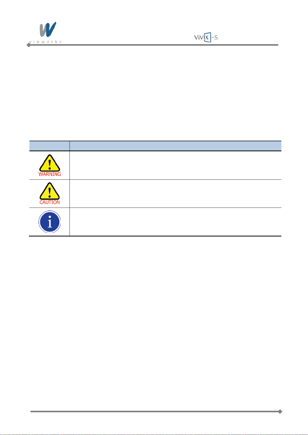
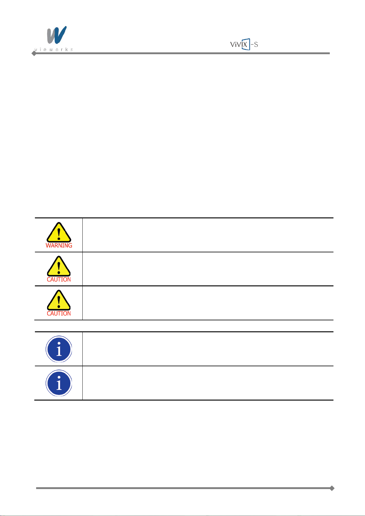
Symbols Descriptions
Indicates a potential ly hazardous situation which will cause death, se vere personal injur y
or substantial property damage if the instructions are ignored.
Indicates a potentially hazardous situation which may cause minor personal
property damage if the instructions are ignored.
Provides additiona l inf ormation that is helpful to you. It may em phas i ze cert ain i nf ormation
regarding special tools or items to check before operating the product.
Page 6 of 124 RA14-11A-022
Page 7
Wireless Service Manual
Safety Information
This product is designed and manufactured to ensure maximum safety of operation and to meet all the
safety requirements applicable to electronic medical equipment. However, anyone attempting to operate the
system must be fully aware of potential safety hazards. It shou ld be opera ted and maintained in strict
compliance with the following safety precautions and operating instruments contained herein:
Caution: Federal law restricts this device to sale by or on the order of a physician or a
licensed practitioner.
Always be alert when operating this device. If a malfunction occurs, do not use this device
until qualified personnel correct the problems.
The product should be installed, maintained and serviced according to Vieworks
maintenance procedures and by Vieworks personnel or other qualified maintenance
personnel approved in writing by Vieworks. Operation and maintenance should be done in
strict compliance with the operation instructions contained in the manuals.
The system, in whole or in part, cannot be m odif ied in any wa y without wr itte n appr oval
from Vieworks.
Before authorizing any person to operate the system, verify that the person has read and
fully understand the Service Manual. The owner should make certain that only properly
trained and fully qualified personnel are authorized to operate the equipment. An
authorized operators list should be maintained.
Prevent unauthorized personnel from access to the system.
It is important that this Service Manual be kept at hand, studied carefully and reviewed
periodically by the authorized operators.
The owner should ensure continuous power supply to the system, with voltage and
current according to the product specifications. If power failures are frequent, an
Uninterrupted Power Supply (UPS) should be installed to avoid loss of data.
If the product does not operate properly or if it fails to respond to the controls described in
this manual, the operator should immediately contact Vieworks field service
representative.
User must not contact a fuse holder or contacts of connector (ex: Inlet connector) with a
patient simultaneously during operating the equipment and not allow patient to touch the
fuse holder or contacts of connector.
Page 7 of 124 RA14-11A-022
Page 8
Wireless Service Manual
The images and calculations provided by this system are intended to be used as tools for
the competent user. They are explicitly not to be regarded as a sole incontrovertible basis
for clinical diagnosis. Users are encouraged to study the literature and reach their own
professional conclusions regarding the clinical utility of the system.
The user should be aware of the product specifications and of the system’s accuracy and
stability limitations. These limitations must be considered before making any decision
based on quantitative values, in case of doubt, please consult a Vieworks representative .
Do not install the equipment in a location with the conditions listed below. Otherwise, it
may result in failure or malfunction, fall or cause fire or injury.
Close to facilities where water is used.
Locations exposed to direct sunlight.
Close to air-conditioner or ventilation equipment.
Close to heat source such as a heater.
Prone to vibration.
Insecure place.
Dusty environm ent.
Saline or sulfurous environment.
High humidity.
Ambient temperature is higher than the operating temperature stated in this Service
Manual.
Occasionally, this product may have defect pixels caused by TFT characteristics. When
the defect pixels are found, perform the Defect detection. For details about how to correct
defect pixels, refer to
5.4.3 Defect Correction.
Do not inflict excessive shock and mechanical vibration. Otherwise, it may result in poor
image quality caused by noise.
Do not unscrew or loosen the screws on the detector surface since all the screws are
secured properly at the time of shipment. Otherwise, it may result in poor image quality or
damage to equipment.
This product may malfunction due to electromagnetic interference (EMI) caused by
telecommunication devices, transceivers, electronic devices, etc. To prevent the
electromagnetic wave from badly influencing the product, be sure to avoid placing it in
close proximity to the product. Or, change direction or position of the product or move into
the shielded place to reduce electromagnetic interference.
To reduce the risk of electric shock, do not remove cover. No user-serviceable part inside.
Refer servicing to qualified service personnel.
Page 8 of 124 RA14-11A-022
Page 9
Wireless Service Manual
Battery Pack and Battery Charger Safety Information
Before using the battery pack and battery charger dedicated to ViVIX-S Wireless, read all applicable
warnings and cautions.
Not following these instructions could result in electrical shock, fire, explosion or other conditions which may
cause death, injury or property damages.
Do not use the battery pack as a power source for equipment other than ViVIX-S Wireless
detectors. Be sure to use only the dedicated battery pack for the ViVIX-S Wireless
detector.
The battery charger is designed for the dedicated battery pack. Do not use the battery
charger other than the dedicated one. Otherwise, a battery explosion or a battery leak
may occur, resulting in fire or electrical shock.
Do not operate the battery charger using any type of power supply other than the one
indicated on the rating label.
Do not handle the product with wet hands.
Do not place heavy objects such as medical equipment on cables and cords, or do not
pull, bend, bundle, or step on them to prevent their sheath from being damaged.
Do not attempt to disassemble, alter, or apply heat to the product.
Avoid dropping or subjecting the product to severe impacts. To avoid the risk of injury, do
not touch the internal parts of the battery if it has been cracked or otherwise damaged.
Stop using the battery pack immediately if it emits smoke, a strange smell, or otherwise
behaves abnormally.
Do not let the battery pack and battery charger come into contact with water or other
liquids and do not allow them to get wet.
Do not clean with substances containing organic solvents such as alcohol, benzene,
thinner, or other chemicals. Otherwise, fire or electrical shock may result.
Page 9 of 124 RA14-11A-022
Page 10
Wireless Service Manual
Do not allow dirt or metal objects (such as hair pins, clips, staples or keys) to contact the
terminals. Otherwise, battery explosion or leakage of electrolyte may occur, resulting in
fire, injury or pollution of surrounding area. If the battery leaks and the electrolytes come
into contact with your eyes, mouth, skin or clothing, immediatel y wash it awa y with runnin g
water and seek medical attention.
Do not leave, store, or place the product in a location near heat sources, or in a place
subject to direct sunlight, high temperature, high humidity, excessive dust, or mechanical
shock. Otherwise, battery leakage, overheating or damage to the product may occur,
resulting in electrical shock, burns, injury or fire.
Do not attempt to use a battery pack that has deteriorated. Using a battery pack that has
exceeded its life cycle may lead to overheating, fire or explosion.
The Lithium ion/polymer battery is recyclable.
Battery slowly discharges even if not in use. The battery pack may have expired if it
discharges immediately after being fully charged. You can purchase an optional b atter y
pack to replace an exhausted one.
The battery pack is a consumable item. If a fully charged battery is consumed quickly, use
a new and fully charged battery pack.
Be sure to charge the battery periodically (once a year) if it is not used for an extended
period of time. The battery pack cannot be charged if it has been over discharged.
Before discarding the battery pack, cover the terminals with adhesive tape or other
insulators. Contact with other metal materials may cause fire or explosion.
Page 10 of 124 RA14-11A-022
Page 11
Wireless Service Manual
General Hazards
Radiation Hazards
This system can be connected to x-ray generating equipment. Be certain to follow the safety instructions and
specifications for wearing proper lead apron when x-ray exposures are planned or possible.
All personnel should wear protective equipment including dosimeters during all phases of installation,
operation and maintenance of the system.
Electric Shock Hazards
To reduce the electric shock hazard, the system must be connected to an electrical ground. A three
conductor AC power cable is supplied with this system to provide the proper electrical grounding. The power
cable must be plugged into an UL-approved three-contact electrical outlet.
Do not disassemble or modify the product as it may result in fire or electric shock. There are no operator
serviceable parts or adjustments inside the systems. Only trained and qualified personnel should be
permitted access to the internal parts of the system.
Explosion Hazards
Do not operate the equipment in the presence of flammable or explosive liquids, vapors or gases. Do not
plug in or turn on the system where hazardous substances are detected.
If flammable substances are detected after the system has been turned on, do not attempt to turn off the
system or unplug it. Evacuate and ventilate the area before turning the system off.
Implosion Hazards
Do not hit or drop the equipment. The equipment may be damaged if it receives a strong jolt, which may
result in fire or electric shock if the equipment is used without it being repaired.
Owner’s Responsibility
The owner is responsible for ensuring that anyone using the system reads and understands the Service
Manual and other relevant literature, and fully understands them. Vieworks makes no representation,
however, that the act of reading this manual renders the reader qualified to operate, test and calibrate the
system.
Do not use the system if unsafe conditions are known to exist. In case of hardware failure
that could cause hazardous conditions (smoke, fire and etc), turn the power OFF and
unplug the power cords of all sub-systems.
Page 11 of 124 RA14-11A-022
Page 12
Wireless Service Manual
Notes for Using the Equipment
System Diagnostic
The VXSetup software runs a system diagnostic. Run VXSetup software after installing the system and at
least once a year. If an error occurs, report the detailed error information to Vieworks local dealer or
distributor.
The owner is responsible for ensuring that the system diagnostic is performed every year.
Do not try to use the system if the system diagnostic is failed.
Calibration
To ensure optimal performance of the system, it is important to verify that the system is calibrated.
The owner is responsible for ensuring that the system calibration is performed after the
system installation is completed or the system is repaired. Do not try to use the system if
system calibration is not performed.
Distances measurements
Distances measurements in millimeters are possible only after distance calibration has been performed using
a reference object (refer to VXvue User Manual).
The operator is responsible for performing distance calibration with a reference object and
verifying the results of the distance calibration before taking any distance measurements
on an image.
Left/Right Marker
The operator is responsible for the correct and clear marking on the left or right side of the image to eliminate
possible errors.
The software includes an option to mark the image with L (left) or R (right) indicator from acquisition phase
through printing and archiving. If the operator chose, for any reason, not to use L/R markers, he must use an
alternative way to eliminate any possible mistake.
Page 12 of 124 RA14-11A-022
Page 13
Wireless Service Manual
Image Backup
To avoid missing images which might result in patient being exposed to additional doses of radiation, it is
important to backup the images by filming or by using a CD or DVD option. This should be done as a routine
operation for every patient.
If the hard disk of your workstation is about to full, the operator should backup images and delete the images
to make room on the hard disk for new patient.
User Limitations
The VXvue software has the technician mode which could only be operated with the inputting PASS WORD.
The technician mode should be operated by the personnel who are qualified by Vieworks.
Cleaning the System
Use a dry cloth to clean surfaces of the system. Do not use detergents or organic solvents to clean the
system. Strong detergent, and organic cleaners may damage the finish and cause structural weakening. Do
not clean the system with turning the power on.
Disposal
Disposal of this product in an unlawful manner may have negative effects on health and on the environment.
When disposing of this product, therefore, be absolutely sure to follow the procedure which is in conformity
with the laws and regulations applicable in your area.
The expected life span of ViVIX-S Wireless system is about 3 years.
Overheating
Do not block the ventilation ports of the detector to prevent overheating of the detector. Overheating can
cause system malfunction and damages.
Electrical fire
This equipment is not suitable for use in the presence of a flammable anesthetic mixture with air or with
oxygen or nitrous oxide.
Conductive fluids that drain into the active circuit components of the system may cause short circuits
that can result in electrical fire. Therefore, do not place fluids or food on any part of the system.
To avoid electric shocks and burns caused by use of the wrong type of fire extinguisher, make sure that
the fire extinguisher at the site has been approved for use on electrical fires.
Page 13 of 124 RA14-11A-022
Page 14
Wireless Service Manual
Handling the Equipment
The Equipment must be handled with care to avoid personal injury damage to the internal image sensor.
Do not put pressure on the detector locally since it will cause permanent damage to
the internal image sensor.
Excessive weight on the equipment may damage the internal image sensor.
It is recommended to use the case, in case if a patient should be positioned to put
pressure on the detector while acquiring images.
Load Limit Specifications
Uniform Load
Local Load
150 ㎏ over the whole area of the detector surface
100 ㎏ on an area 40 ㎜ in diameter
Pediatric Application
Every request should be reviewed by the pediatric radiologist prior to beginning the examination to
insure correct study is being performed.
If the technologist notices an unusual request, they should contact the pediatric radiologist. An example
should be from pediatric clinic where they order a Full Cervical, Thoracic, and Lumbar Spine series. The
pediatric radiologist should contact ordering physician and decide which study is the best for this
pediatric patient.
The technologist should use the proper technique for the patient’s size to decrease the radiation dose
when the technologist acquires diagnostic images.
ALL Pediatric patients shall be shielded for their x-ray examinations, except for when the shield will
obscure the region of interest, as in a pelvic or SI joint xray for trauma or arthritis, or when it is physically
or clinically unreasonable to shield the patient. For routine Hip X-Rays, ALL male children shall have
their scrotum shielded using the small gonadal shield, females may not be shielded as this wou ld
obscure the hips.
To minimize motion in infants and young children, swaddle the infant. Use distraction tools to improve
cooperation and projectors with child-friendly themes, music, toys with flashing lights or music, childfriendly images on the ceiling or walls, singing, counting, and a parent reading and talking to the child
through the console all can help reduce anxiety and comfort the child.
A Scoliosis series will consist of a single frontal standing view of the spine. No lateral view or supine
view is needed, unless specifically asked for by the Orthopedist or Radiologist. If the female’s breasts
can be shielded without obscuring the spine, breast shields should be used.
Page 14 of 124 RA14-11A-022
Page 15
Wireless Service Manual
Regulatory
Medical Equipment Classifications
Type of protection against electrical shock
Degree of protection against ingress of water IPXO
Mode of operation Continuous operation
Flammable anesthetics NOT suitable for use in the presence of a flammable
Class Ⅰ equipment
anesthetic mixture with air or with oxygen or nitrous oxide.
Equipment Standards
IEC/EN/UL 60601-1 Medical electrical equipm ent
CSA C22.2 No. 601.1 Part 1: General requirements for safety
IEC/EN 60601-1-2 Medical electrical equipm ent
Part 2: Electromagnetic compatibility–requirements and tests
IEEE 802.11a/b/g/n Wireless Communications
Page 15 of 124 RA14-11A-022
Page 16
Wireless Service Manual
Guidance and Manufacturer’s Declaration for EMC Directive
This device has been tested for EMI/EMC compliance, but interference can still occur in an
electromagneticall y nois y location. Attempt to maintain a suitable distance between electrical devices to
prevent malfunction.
Electromagnetic Emissions
The Equipment Under Test (EUT) is intended for use in the electromagnetic environment specified below.
The customer or user of the EUT should assure that it is used in such an environment.
Immunity Test Compliance Electromagnetic Environment – Guidance
RF Emissions
CISPR 11
RF Emissions
CISPR 11
Harmonic emissions
IEC 61000-3-2
Voltage fluctuations/
Flicker emissions
IEC 61000-3-3
Group 1 The EUT uses RF energy only for its internal function. Therefore, its
RF emissions are very low and are not likely to cause any
interference in nearby electronic equi pment.
Class A The EUT is suitable for use in all establishments other than
domestic and those directly connected to the public low-voltage
Class A
power supply network that supplies buildings used for domestic
purposes.
Complies
Page 16 of 124 RA14-11A-022
Page 17
Wireless Service Manual
IEC 60601
Test Level
Compliance
Level
±6 ㎸
±6 ㎸
±2㎸ for
lines
±2㎸ for
lines
±1 ㎸
mode
±1 ㎸
mode
<5% Uт
Uт) for 5 sec.
<5% Uт
Uт) for 5 sec.
Electromagnetic Immunity
The EUT is intended for use in the electromagnetic environment specified below.
The customer or user of the EUT should assure that it is used in such an environment.
Immunity Test
Electrostatic
discharge (ESD)
IEC 61000-4-2
Electrical fast
transient/burst
IEC 61000-4-4
Surge
IEC 61000-4-5
Voltage dips, short
interruptions and
voltage variations
on power supply
input lines
IEC 61000-4-11
contact
±8 ㎸ air
power supply
lines
± 1 ㎸ for
input/output
differential
mode
±2 ㎸
common
(>95% dip in
Uт) for 0.5
cycle.
40% Uт
(60% dip in
Uт) for 5
cycles.
70% Uт
(30% dip in
Uт) for 25
cycles.
contact
±8 ㎸ air
power supply
lines
± 1 ㎸ for
input/output
differential
mode
±2 ㎸
common
(>95% dip in
Uт) for 0.5
cycle.
40% Uт
(60% dip in
Uт ) for 5
cycles.
70% Uт
(30% dip in
Uт) for 25
cycles.
Electromagnetic Environment – Guidance
Floors should be wood, concrete or ceramic tile. If
floors are covered with synthetic material, the relative
humidity should be at least 30%.
Mains power quality should be that of a typical
commercial or hospital environment.
Mains power quality should be that of a typical
commercial or hospital environment.
Mains power quality should be that of a typical
commercial or hospital environment. If the user of the
EUT image intensifier requires continued operation
during power mains interruptions, it is recommended
that the EUT image intensifier be powered from an
uninterruptible power supply or a battery.
Power frequency
(50/60 ㎐)
magnetic field
<5% Uт
(<95% dip in
3 A/m 3 A/m Power frequency magnetic fields should be at lev els
<5% Uт
(<95% dip in
characteristic of a typical location in a typical
commercial or hospital environment.
IEC 61000-4-8
NOTE: Uт is the a.c. mains voltage prior to application of the test level.
Page 17 of 124 RA14-11A-022
Page 18
Wireless Service Manual
IEC 60601
Test Level
Compliance
Level
3 Vrms 150
3 Vrms 150
Immunity Test
Conducted RF
IEC 61000-4-6
Radiated RF
IEC 61000-4-3
㎑ to 80 ㎒
3 V/m 80 ㎒
to 2.5 ㎓
㎑ to 80 ㎒
3 V/m 80 ㎒
to 2.5 ㎓
Electromagnetic Environment – Guidance
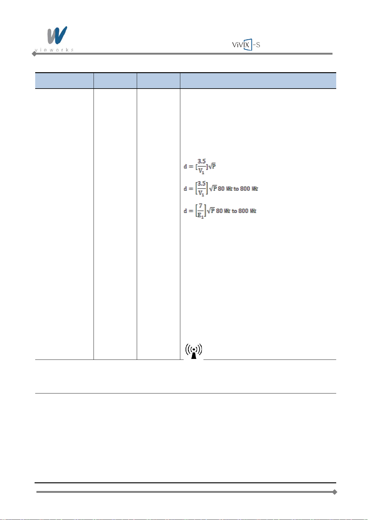
Portable and mobile RF communications equipment
should be used no closer to any part of the EUT,
including cables, than the recommended separation
distance calculated from the equation applicable to the
frequency of the transmitter.
Recommended separation distance
Where P is the maximum output power rating of the
transmitter in watts (W) according to the transmitter
manufacturer and d is the recommended separation
distance in meters (m).
Field strengths from fixed RF transmitters, as
determined by an electromagnetic site survey
a
, should
be less than the compliance level in each frequency
b
range.
Interference may occur in the vicinity of equipment
marked with the following symbol:
NOTE 1: At 80 ㎒ and 800 ㎒, the higher frequency range applies.
NOTE 2: These guidelines may not apply in all situations. Electromagnetic propagation is affected by
absorption and reflection from structures, objects and people.
a
Field strengths from fixed transmitters, such as base stations for radio (cellular/cordless) telephones and
land mobile radios, amateur radio, AM and FM radio broadcast and TV broadcast cannot be predicted
theoretically with accuracy. To assess the electromagnetic environment due to fixed RF transmitters, an
electromagnetic site survey should be considered. If the measured field strength in the location in which
the EUT is used exceeds the applicable RF compliance level above, the EUT should be observed to
verify normal operation. If abnormal performance is observed, additional measures may be necessary,
such as reorienting or relocating the EUT.
b
Over the frequency range 150 ㎑ to 80 ㎒, field strengths should be less than [V1] V/m.
Page 18 of 124 RA14-11A-022
Page 19
Wireless Service Manual
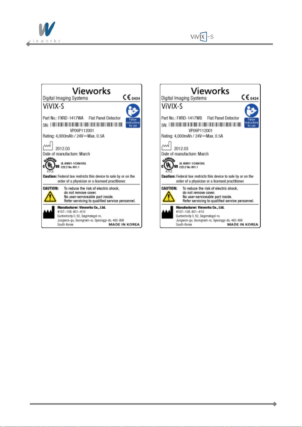
Label and Symbols
Detectors
FXRD-1417WA FXRD-1417WB
Page 19 of 124 RA14-11A-022
Page 20
Wireless Service Manual
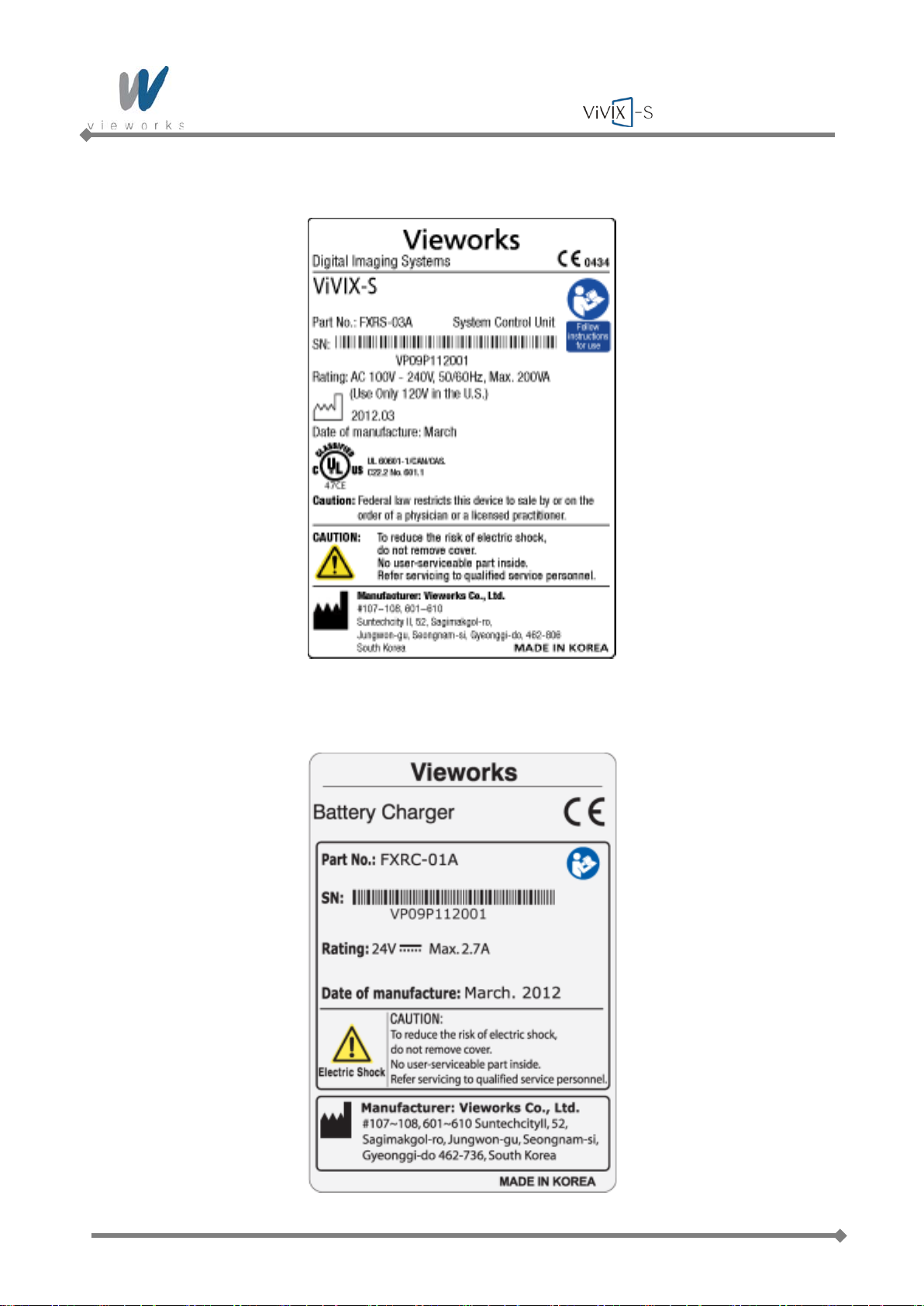
System Control Unit
Battery Charger
Page 20 of 124 RA14-11A-022
Page 21
Symbols
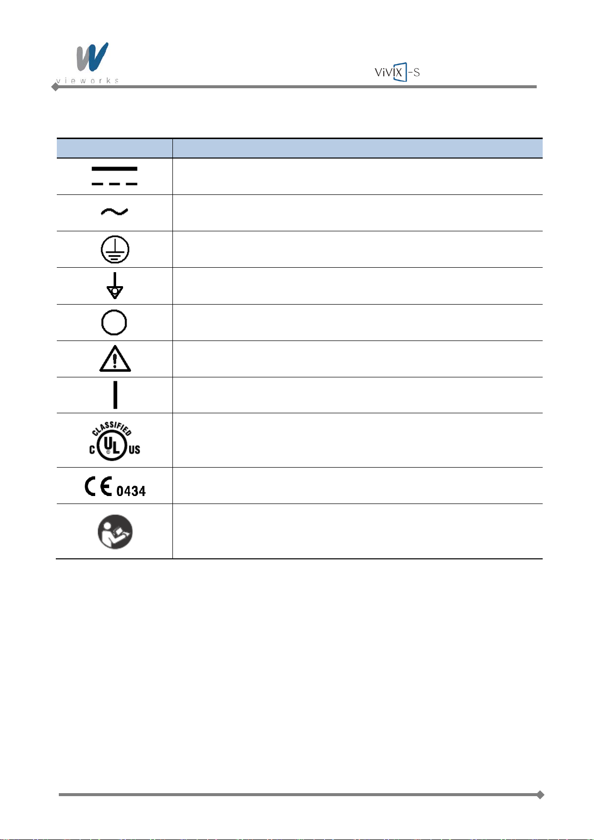
Symbol Description
Wireless Service Manual
Direct Current
Alternating Current
Protective Earth (Ground)
Equipotentiality
Power Off
Attention, consult accompanying documents
Power On
Medical Equipment
With Respect to electric shock, fire, and mechanical hazards only
In accordance with UL60601-1 and CAN/CSA C22.2 No. 601.1.
This mark shows compliance of the equipment with Directive 93/42/EEC.
Read and understand all instructions and war nin g lab e ls in the produc t
documentation before using the equipment.
Keep manual for future reference.
Page 21 of 124 RA14-11A-022
Page 22

Wireless Service Manual
1. Overview
The ViVIX-S Wireless is advanced wire less flat panel X-ray imaging system designed for digital radiography.
The lightweight wireless digital radiography is designed to be compatible with conventional X-ray film
cassettes so that the users who are not familiar with Digital Radiography (DR) can easily understand and use
the ViVIX-S system. In addition, the wireless communication (IEEE 802.11a/b/g/n) feature improves the
operability and high-speed processing.
1.1 Features
Wireless LAN communication (IEEE 802.11a/b/g/n) feature
Supporting Conventional 35 × 43 X-ray film cassette
Compatible with not only new X-ra y generat ors based on DR inter f ace but also conventional X-ray
generators
Designed with simple wiring and lightweight for portable applications
Image digitization, image inversion, image processing, zooming, panning, window level adjustment,
contrast adjustment, and various features enable the operator to see diagnostic details th at is difficult to
see by using conventional non-digital techniques.
Depending on the operating environment, the Ether Con Cable (optional) enables the device to be used
through expansion to a wired connection.
1.2 Intended Use
The ViVIX-S Digital X-ray detector is indicated for digital imaging solution designed for providing general
radiographic diagnosis of human anatomy. This device is intended to replace film or screen based
radiographic systems in all general purpose diagnostic procedures. This device is not intended for
mammography applications.
Page 22 of 124 RA14-11A-022
Page 23

Wireless Service Manual
Detector
System Control Unit
ViVIX-S Viewer
Gigabit Ethernet
Cables supplied with equipment
X-ray System
Generator
Vieworks
Generator Interface
Tether Interface
Battery Charger
Stand
Viework
s
Viewo
rks
Please
~
1.3 Standard Configuration
Figure 1.1 ViVIX-S Wireless System Configuration
Wireless communication is established between the ViVIX-S Wireless detector and System Control Unit. The
ViVIX-S system is compliant with IEEE 802.11a/b/g/n (2.4 ㎓ / 5 ㎓). The available frequency band may
vary depending on local radio laws and system requirements. Consult your local dealer for the frequency
available in your area.
Use of multiple WLAN devices within the same frequency band may interfere with each
wireless communication and cause a decline in transmission speed.
Do not cover or block the wireless module of the detector. Otherwise, the transmission
speed or operable distance may be reduced.
Recommended maximum operating distance of wireless communication between the
detector and System Control Unit is 8 meters.
Page 23 of 124 RA14-11A-022
Page 24

Wireless Service Manual
2. Product Description
ViVIX-S Wireless system consists of detector, system control unit (SCU), battery charger, battery pack,
software and its accessories.
2.1 Product Components
Detector
FXRD-1417WA (scintillator: CsI (TI))
FXRD-1417WB (scintillator: Gadox)
System Control Unit (SCU)
FXRS-03A
Battery Charger and Battery Pack
FXRC-01A
FXRB-01A
Software
Viewer: VXvue
Calibration and Diagnostic: VXSetup
Page 24 of 124 RA14-11A-022
Page 25
Wireless Service Manual
Accessories (Cables)
AC Power Cable (2M)
Generator Interface Cable (15M)
Direct LAN Cable 15M (1000BASE-T)
Tether Interface Cable (3M)
The use of accessories and cables other than those specified, with the exception of
ViVIX-S Wireless accessories and cables sold by Vieworks Co., LTD. as replacement
parts for internal components, may result in increased emissions or decreased immunity
of the equipment.
Accessory equipment connected to the analog and digital interfaces must be certified
according to the respective IEC standards. All combinations of equipment must be in
compliance with IEC 60601-1-1 system requirements. Any person who connects
additional equipment to the signal input or signal output ports configures a medical
system, and is therefore responsible for ensuring that the system complies with the
requirements of the system standard IEC 60601-1. If in doubt, consult Vieworks technical
support representative.
Workstation (Recommended but NOT included)
Operating System Microsoft Windows XP 32 bit SP3 (Professional Edition),
Windows 7 32 bit SP1 (Pr of es siona l Edi tio n or higher) or
Windows 7 64 bit SP1 (Professional Edition or higher)
CPU Intel Core i5 2600 or higher (or equivalent AMD chips)
Memory 2 GB or higher
Hard Disk 1 TB or higher
Ethernet (NIC) Intel® PRO 1000 Series (PT, CT, etc)
Min. Requirements: 1Gbps, Jumbo Frames - 9K, Receive Descriptors - 2K
Monitor 1280 × 800 or higher
CD-Rom CD or DVD R/W or blu-ray
Page 25 of 124 RA14-11A-022
Page 26
Wireless Service Manual
2.2 Detector
2.2.1 Detector Specifications
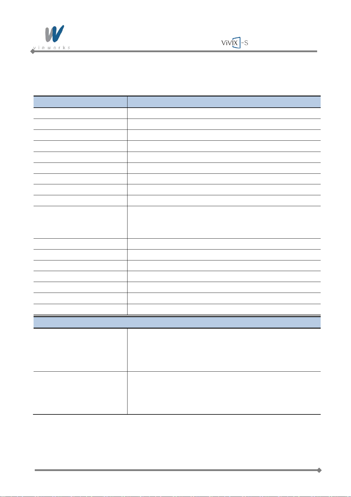
Item Description
Model FXRD-1417WA(B)
Purpose General radiography
Image Matrix Size
Pixel Pitch
Effective Imaging Area
2560 × 3072 pixels
140 ㎛
358 ㎜ × 430 ㎜
Grayscale 14 bit, 16,384 grayscale
Scintillator CsI (Cesium Iodide) or Gadox (Gadolinium Oxysulfide)
Image Acquire and Transfer Time Preview: 2 s, Image Processing: 6.5 s (2 s when using Tether Interface)
Spatial Resolution
Rated Power Supply
Wireless
Wired
Min. 3.5 line pair/㎜
DC +24 V, Max. 0.5 A
Powered by the battery pack (4,000 ㎃ h)
Powered by the SCU using tether interface
Power Consumption Max. 12 W
Wireless Communications
†
Tether Interface (Optional) Gigabit Ethernet (1000BASE-T) via ‡PoE
IEEE 802.11a/b/g/n (2.4 ㎓ / 5 ㎓)
Imaging Plate Carbon Fiber Plate
Cooling Air cooling
Dimensions (H × W × D)
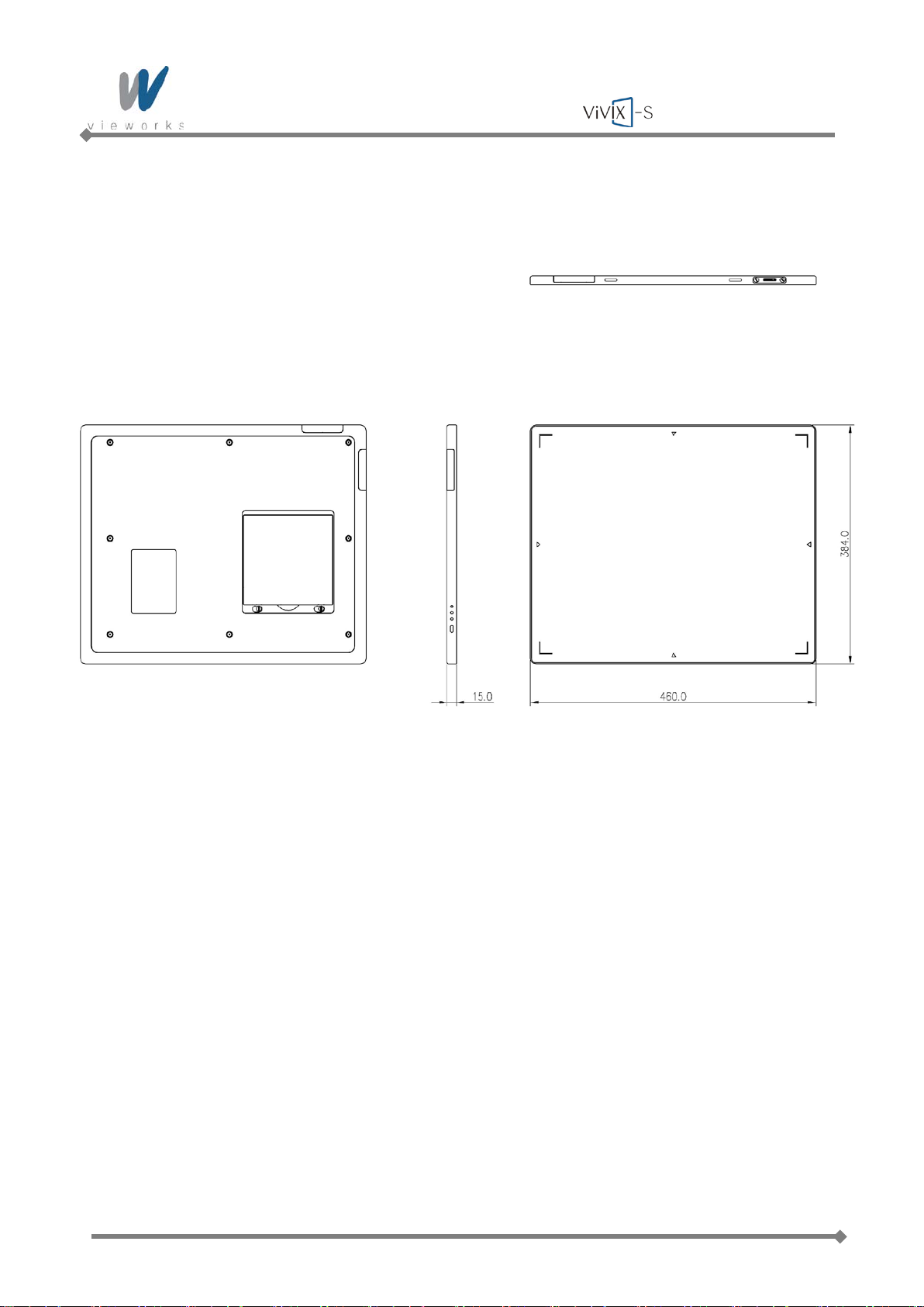
384 ㎜ × 460 ㎜ × 15 ㎜
Weight
3.0 ㎏ (including battery pack)
Environmental Requirements
Operation Temperature: +10 ∼ +35℃
Humidity: 30 ∼ 85% (Non-Condensing)
Atmospheric pressure: 70 ∼ 106 ㎪
Altitude: Maximum 2000 meters
Storage and transportation Temperature: -15 ∼ +55℃
Humidity: 10 ∼ 90% (Non-Condensing)
Atmospheric pressure: 50 ∼ 106 ㎪
Altitude: Maximum 2000 meters
Tab le 2.1 Detector Specifications
†
Tether Interface: Allows the detector to communicate with SCU via Ethernet cabling when wireless communications is
not available or higher speed data transfer is necessary.
‡
PoE (Power over Ethernet): Delivers electrical power over LAN cablin g to the netw orked dev ice.
Page 26 of 124 RA14-11A-022
Page 27
Wireless Service Manual
2
1
A
B
C
D
3
4
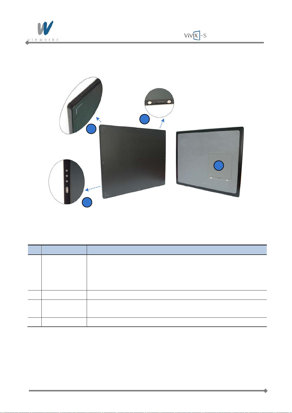
2.2.2 Detector Components
Figure 2.1 Detector Components
No. Name Description
1 Status Indicators
Power button
2 Wireless Module Transmits data with wireless communications (IEEE 802.11a/b/g/n).
3 Tether Interface Allows the detector to communicate with SCU via PoE cabling (Gigabit Ethernet
A: Data LED, Indicates communication and transmission status. - Blue
B: Active LED, Indicates the detector is ready to work. - Orange
C: Power LED, Indicates power on/off status. - Green
D: Power button, Press to power on or off the detector.
1000BASE-T)
4 Battery Pack Supplies electrical power to the detector while communicating wirelessly.
Tab le 2.2 Detector Components Description
Page 27 of 124 RA14-11A-022
Page 28
Wireless Service Manual
2.2.3 Detector Dimension
Figure 2.2 Detector Dimension
Page 28 of 124 RA14-11A-022
Page 29
Wireless Service Manual
2.3 System Control Unit
2.3.1 System Control Unit Specifications
Item Description
Model FXRS-03A
Power Supply
Cabling Ports Gigabit Ethernet Ports – 3EA
Wireless Communications
Dimensions (W × H × D)
Weight
Environmental Requirements
Operation
Storage and transportation Temperature: -15 ~ +55℃
Input: AC100 to 240V, 50/60 ㎐, Max. 200VA
Output: DC +24V 3.3A, 80W
Power over Ethernet Ports – 2EA (Only for FXRD-1417)
IEEE 802.11a/b/g/n (2.4 ㎓ / 5 ㎓)
300 ㎜ × 235.8 ㎜ × 58 ㎜, Antenna Height – 105 ㎜
2.5 ㎏
Temperature: +10 ~ +35℃
Humidity: 30 ∼ 85% (Non-Condensing)
Atmospheric pressure: 70 ∼ 106 ㎪
Altitude: Maximum 2000 meters
Humidity: 10 ∼ 90% (Non-Condensing)
Atmospheric pressure: 50 ∼ 106 ㎪
Altitude: Maximum 2000 meters
Tab le 2.3 System Control Unit Specifications
Page 29 of 124 RA14-11A-022
Page 30
Wireless Service Manual
1
2
3
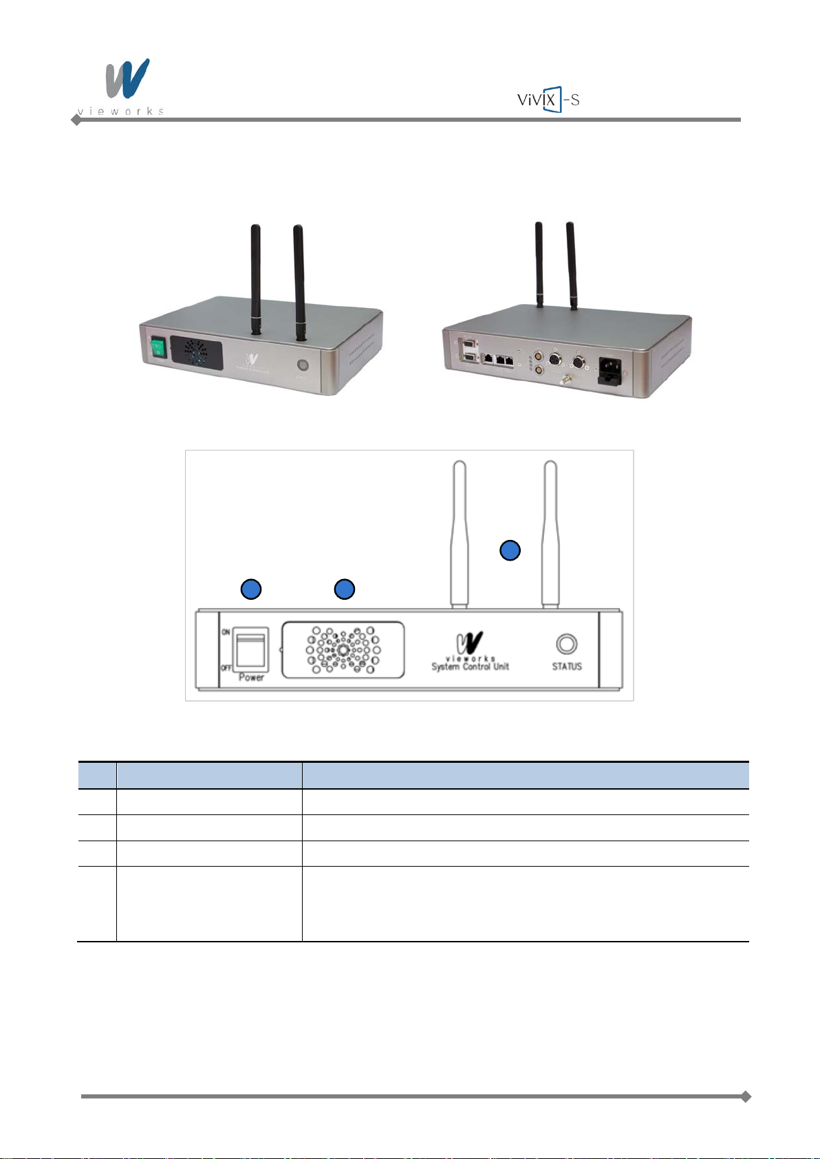
2.3.2 System Control Unit Components
Figure 2.3 System Control Unit (Front)
No. Name Description
1 Power S w i tch Turns on or off the SCU.
2 Fan Expels heated air inside of the SCU.
3 Antenna Assists communi cations between the detector and SCU.
4 Status LED Indicates status of SCU operation and connection.
Blinking Green: Startup in progress
Blue: Connected to Wi-Fi network
Tab le 2.4 System Control Unit Components (Front)
Page 30 of 124 RA14-11A-022
Page 31
Wireless Service Manual
1
2
3
4
5
6
7
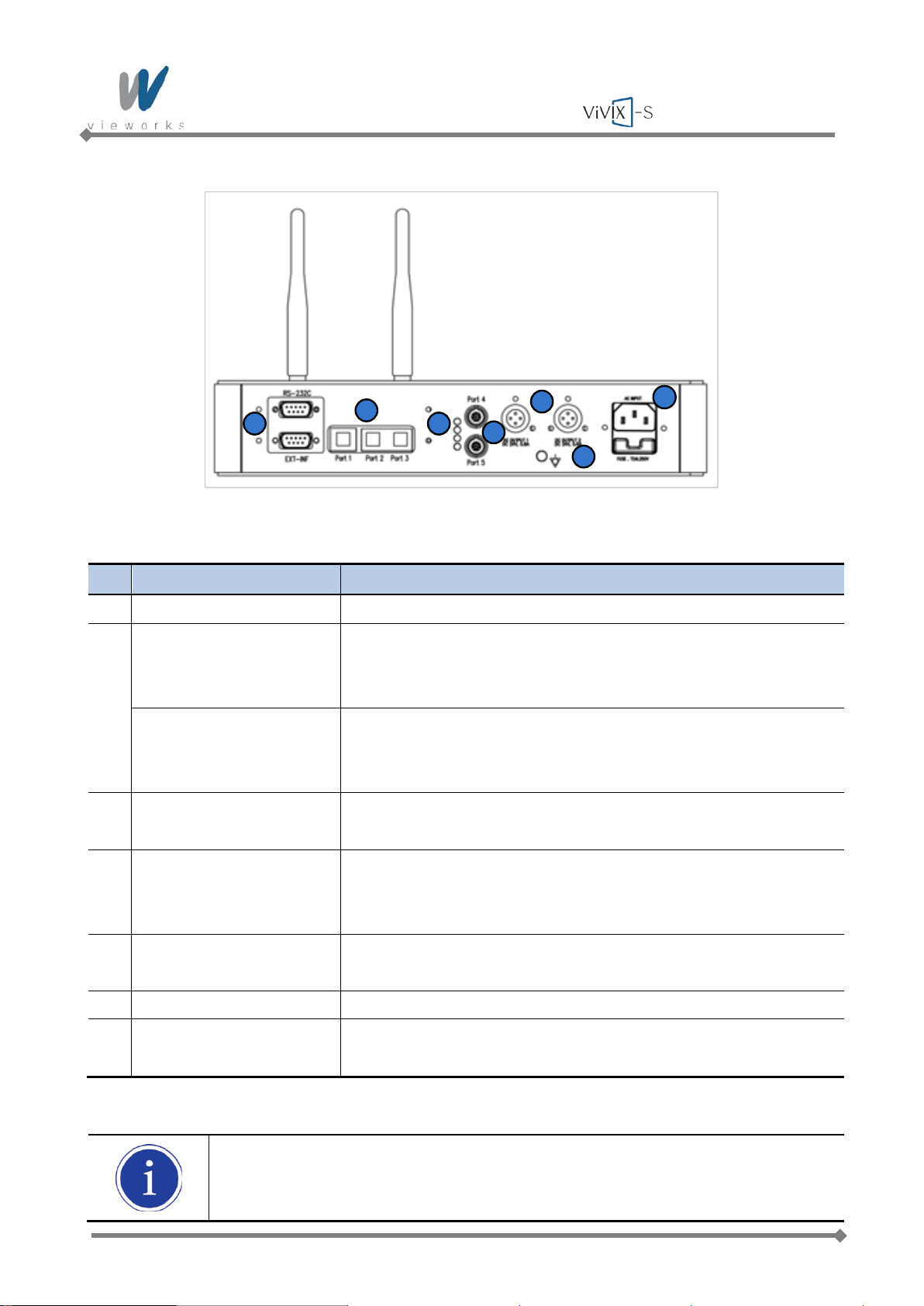
Figure 2.4 System Control Unit (Back)
No. Name
1 EXT_INF Provides connection to the X-ray generator.
2 Port 1 Provides Gigabit Ethernet (1000BASE – T) communication
between the workstation and SCU.
Gigabit Ethernet (1000BASE – T) Port
Port 2, Port 3 Provides communication between FXRD-1717 and SCU when
configuring multiple detectors.
Gigabit Ethernet (1000BASE – T) Port
3 Status LED Indicates Port 4 and Port 5 status (Green: 1Gbps, Orange:
100Mbps)
4 Port 4, Port 5 Connection interface to communicate with the detector and to
supply electrical power to the detector (Only for FXRD-1417).
Power over Ethernet Port (1000BASE-T)
5 Power Supply Connection interface to supply power to a FXRD-1717 detector.
Max. DC +24V/24W (×2 ports)
6 P.E Provides connection to equipotential ground.
Description
7 AC Input Connect the power cable to the power socket.
100 ~ 240V, 50/60 ㎐, T2AL250V Fuse (2 EA)
Tab le 2.5 System Control Unit Components (Back)
P.E (Potential Equalization) of SCU is used to keep equipotential between SCU and an
equipment to be used with ViVIX-S Wireless. To connect to P.E of equipment, use a
ground cable.
Page 31 of 124 RA14-11A-022
Page 32
Wireless Service Manual
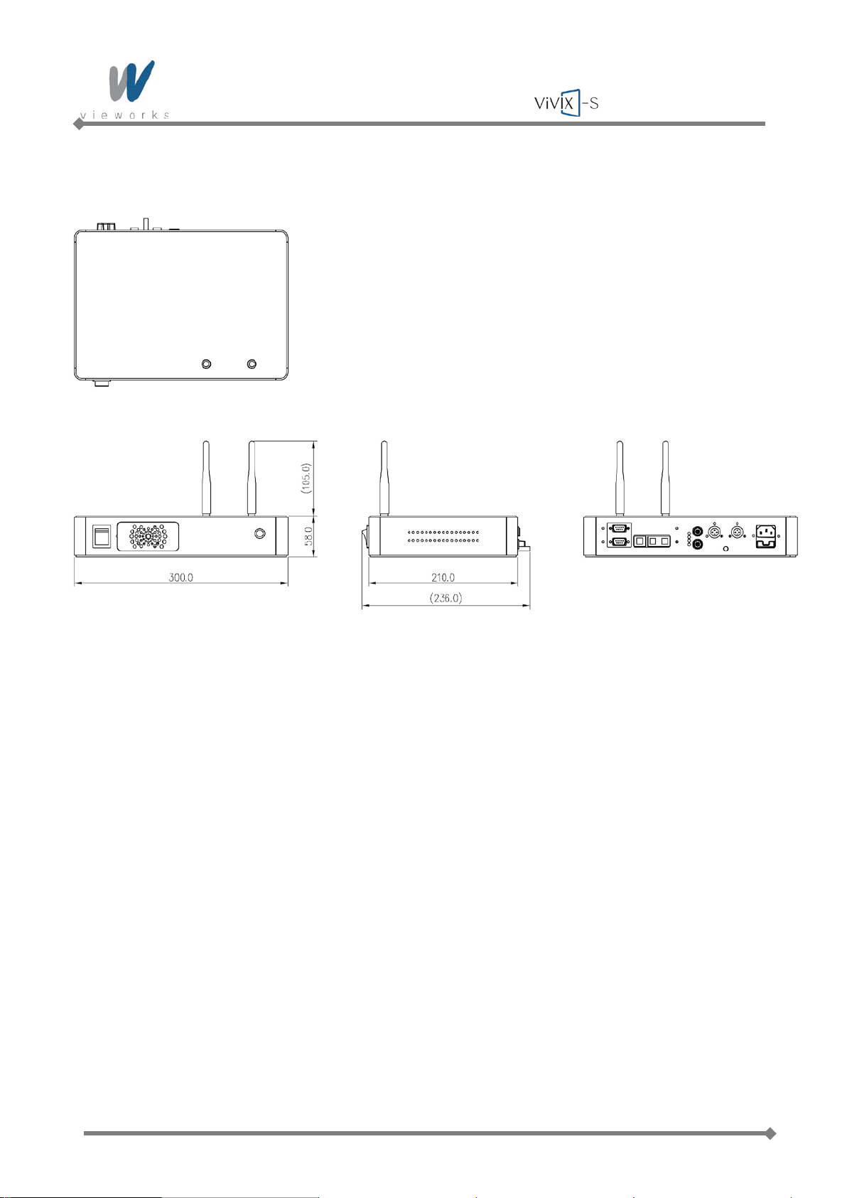
2.3.3 SCU Dimension
Figure 2.5 SCU Dimension
Page 32 of 124 RA14-11A-022
Page 33
Wireless Service Manual
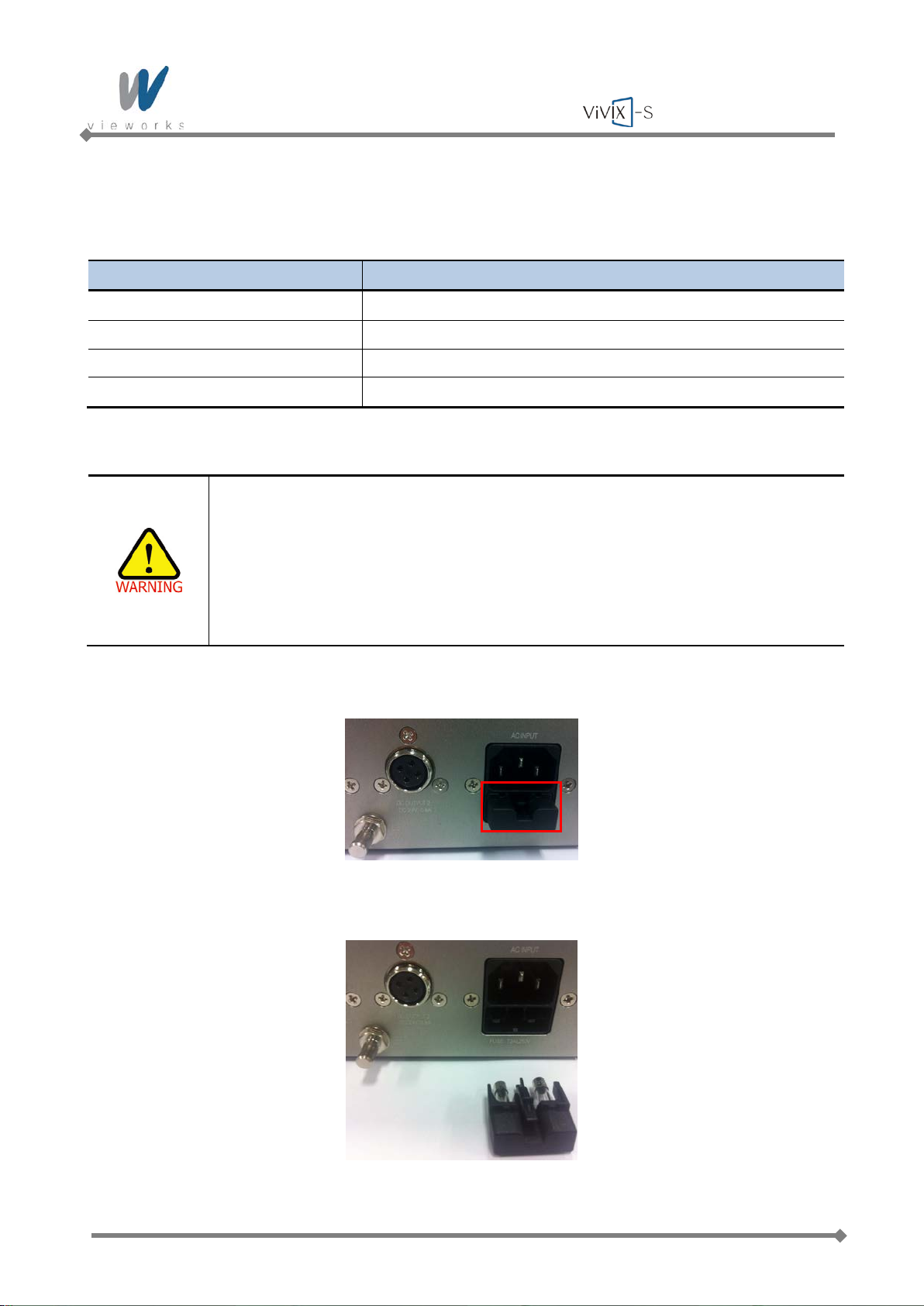
2.3.4 Fuse
Two fuses are installed inside of SCU to prevent electrical accidents due to an error such as overcurrent
occurred in the AC Input. Stop immediately using SCU when fuses break.
Item Description
Model
Littlefuse
Type Time Lag Cartridge Fuse
Amp Rating 2 A
Voltage Rating 250 V
Replacing Fuses
Turn off SCU and its peripheral equipment, and pull the plug out of the power socket
before replacing fuses.
When fuses break, resolve the cause of overcurrent first, and then replace the fuses
®
218002 (2 EA)
with extra fuses (optional items, one set of two) or equivalent rating fuses.
User must not contact a fuse holder with a patient simultaneously during operating
the equipment and not allow patient to touch the fuse holder.
1. Pull the fuse holder out from its receptacle under AC Input on the back panel of SCU.
2. Check the fuse(s) and replace it if necessary, using the fuse type and rating specified above.
3. Push the fuse holder back.
Page 33 of 124 RA14-11A-022
Page 34
Wireless Service Manual
1
2
3
4
2.4 Battery Charger and Battery Pack
2.4.1 Battery Charger Specifications
Item Description
Model FXRC-01A
Simultaneous Charging Batter y Pack 3 EA
Charging Time 2 hours
Rated Power Supply DC +24V, 2.7 A Max.
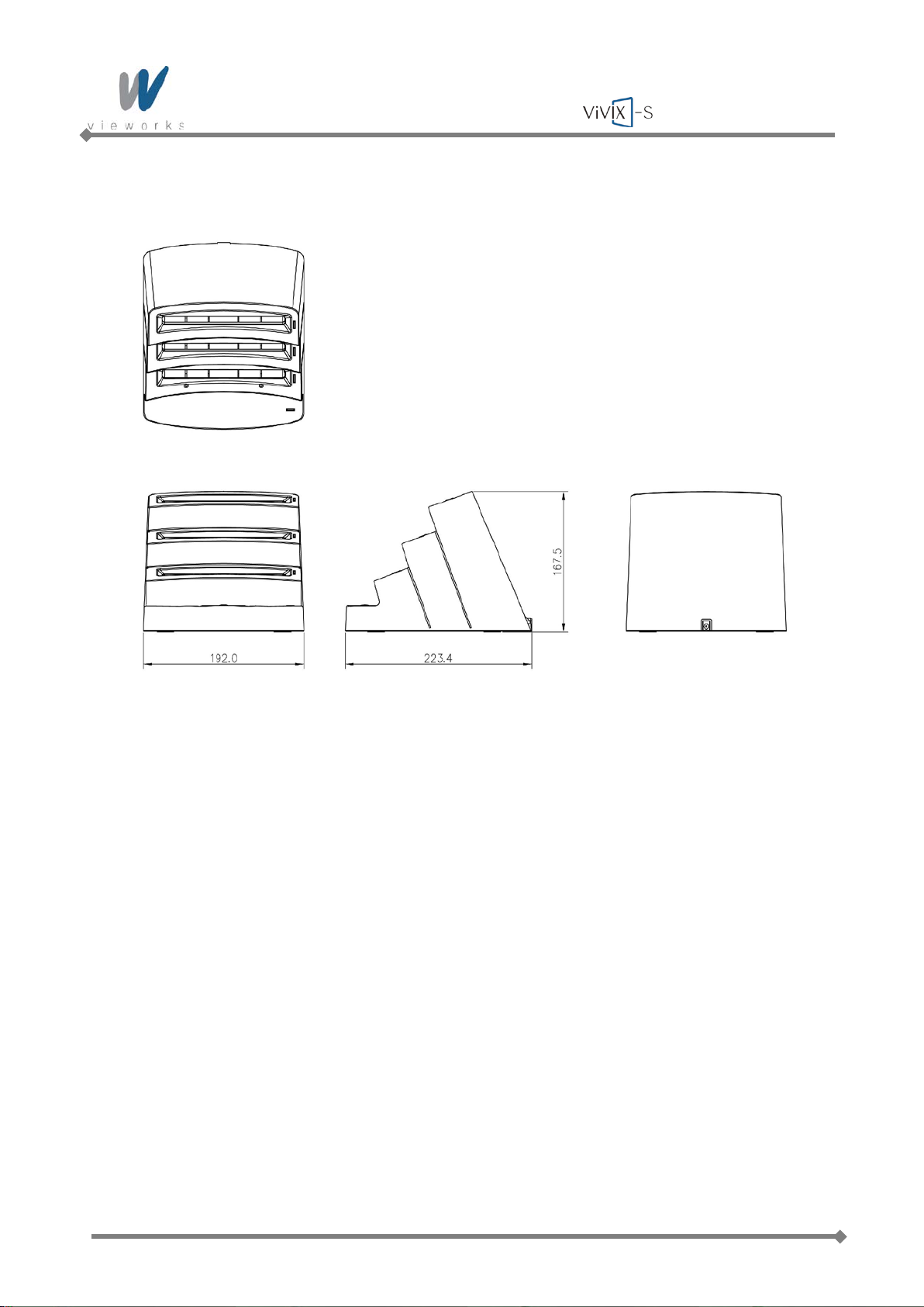
Dimension (W × H × D) 192.0 ㎜ × 167.5 ㎜ × 223.4 ㎜
Weight
Tab le 2.6 Battery Charger Specifications
1.2 ㎏
2.4.2 Battery Charger Components
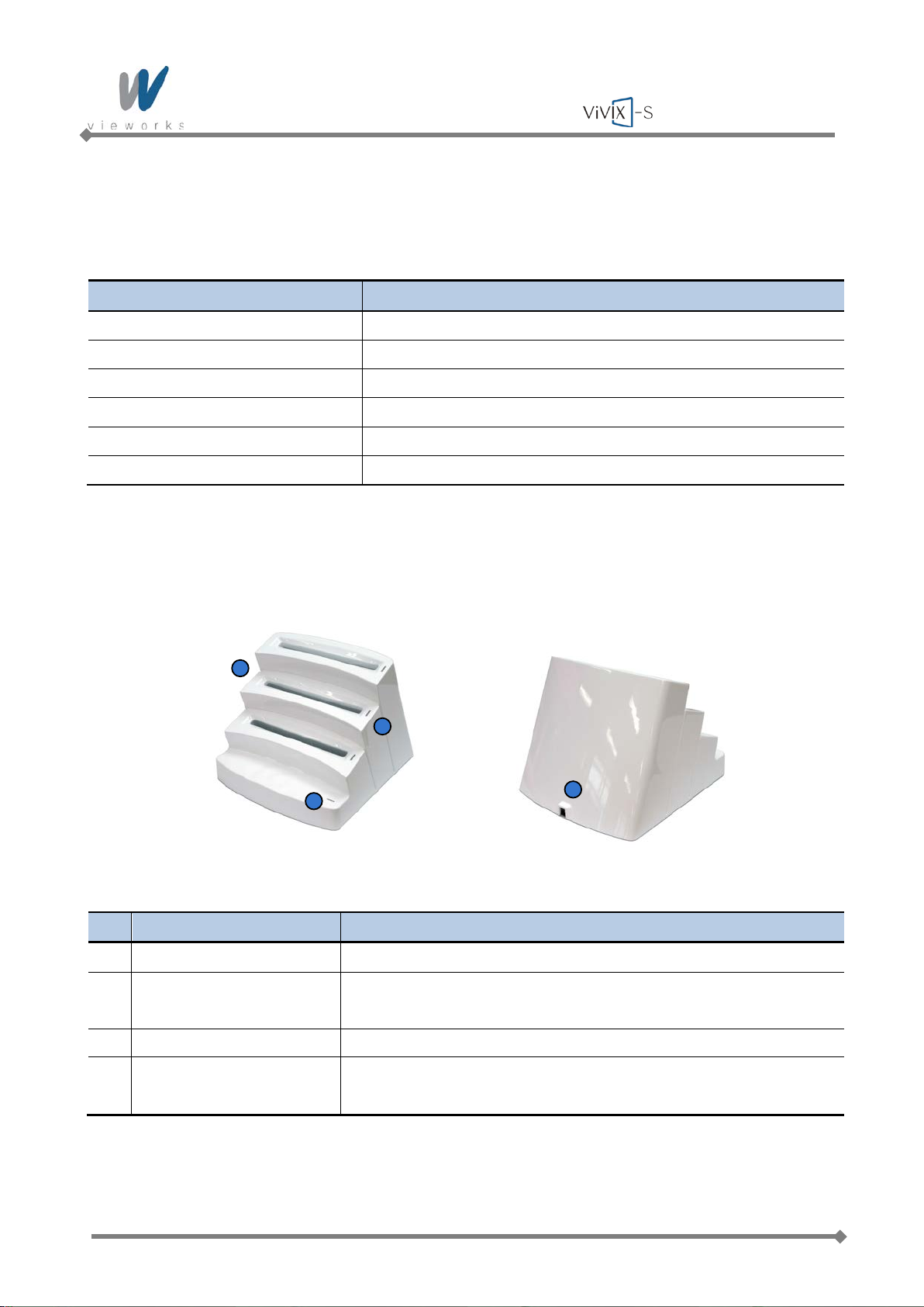
Figure 2.6 Battery Charger
No. Name Description
1 Battery Compartment Insert the battery pack to charge.
2 Charging Indicator Indicates the charging status.
(Orange: Charging, Green: Fully Charged)
3 Power Indicator Indicates the power on/off status.
4 DC Input Connect the DC adapter to supply electrical power to the battery
charger.
Page 34 of 124 RA14-11A-022
Tab le 2.7 Battery Charger Components
Page 35
Wireless Service Manual
2.4.3 Battery Charger Dimension
Figure 2.7 Battery Charger Dimension
Page 35 of 124 RA14-11A-022
Page 36
Wireless Service Manual
2.5 Battery Pack
2.5.1 Battery Pack Specifications
Item Description
Model FXRB-01A
Type Lithium Polymer
Rated Power Supply Output: DC +7.4V
Capacity
Number of Cell 2S1P (2 Series 1 Parallel)
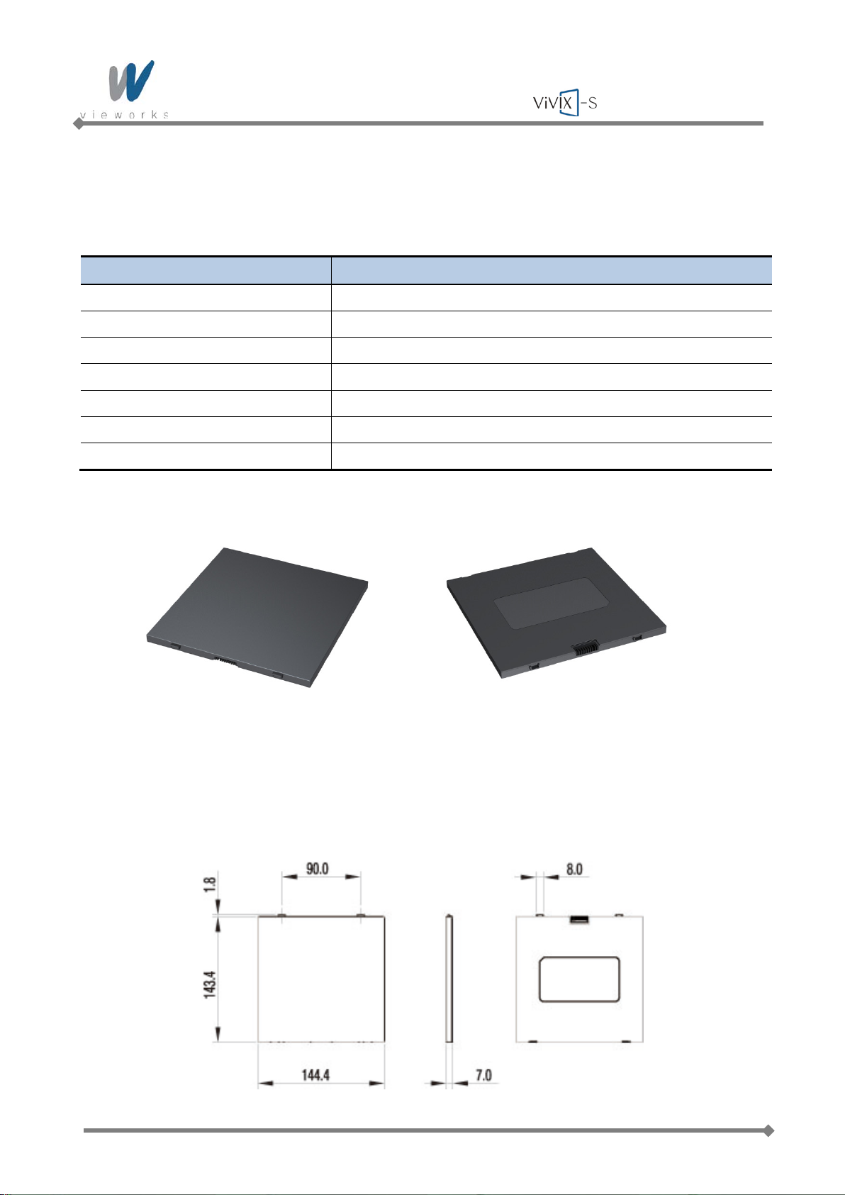
Dimension (W × H × D) 144.4 ㎜ × 143.4 ㎜ × 7.0 ㎜
Weight 220 g
Tab le 2.8 Battery Pack Specifications
4000 ㎃ h
Figure 2.8 Battery Pack
2.5.2 Battery Pack Dimension
Figure 2.9 Battery Pack Dimension
Page 36 of 124 RA14-11A-022
Page 37
Wireless Service Manual
2.5.3 Charging Batter y Pack
The battery pack supplies power to the detector during wireless connection. Be sure to use only the
dedicated battery pack and fully charge it before use.
1 Connect the power cable (adapter not included) to the DC Input port of the battery charger and the
power cord to the power source to supply power. The power LED lights in green in dicat ing the pr es ence
of direct current (DC) power.
2 Insert the battery pack into the battery charger. Charging starts automatically. The charge LED lights
orange when the battery pack is being charged. After the battery pack is charged completely, the charge
LED lights in green.
3 Gently pull the charged battery pack to remove from the battery charger.
Securely plug the power cord into the power source. If contact failure occurs, or if dust or
metal objects come into contact with the exposed metal prongs of the plug, fire or
electrical shock may occur.
Be sure to stop charging the battery pack when the charge LED lights in green beyond the
specified charging time. Not doing so may result in battery pack overheating or smoking or
in explosion or fire.
You must use the power adaptor that is certified with IEC 60950 or IEC 60601-1.
Three batteries can be charged at the same time.
It takes approximately two hours to fully charge a battery pack. The required charging time
may vary depending on the temperature and remaining battery level.
Page 37 of 124 RA14-11A-022
Page 38

Wireless Service Manual
Detector
X-ray System
Generator
Exposure Request
Exposure OK
Generator Interface Cable
2.6 X-ray Generator Interface
2.6.1 X-ray Exposure Mode
Mode Description
DR Trigger Mode 1 The detector receives EXP_REQ signal that X-ray generator is prepared to
generate X-rays.
2 The detector prepares image acquiring and then responds EXP_OK signal to the
X-ray generator.
3 The X-ray generator confirms EXP_OK signal and generates X-rays, then the
detector performs image acquiring according to Image Acquisition Time and
transmits the image data.
EXP_REQ (Generator → Detector), EXP_OK (Detector → Generator)
AED Mode The detector detects actual amount of X-rays without any connection to the X-ray
generator, and then performs image acquiring according to Image Acquisition Time
and transmits the image data.
No signal used (No need to connect Generator Interface Cable.)
2.6.1.1 DR Trigger Mode
Figure 2.10 DR Trigger Mode Configuration
Tab le 2.9 Exposure Mode
DR Trigger is the most common and recommended exposure mode. User can achieve the best quality
images with DR Trigger Mode.
Page 38 of 124 RA14-11A-022
Page 39
Wireless Service Manual
Detector
X-ray System
Generator
2.6.1.2 AED Mode
Figure 2.11 AED Configuration
AED is available for acquiring images without any connection to X-ray generator. Generator interface
cable is not required.
Make sure to follow operating environmental requirements (Temp: +10℃ ~ +35℃).
If you use AED Mode out of operating environmental requirements, unwanted image
can be acquired without X-ray image acquiring.
Do not hit or drop the equipment. Unwanted images may be acquired in the AED
Mode if it receives strong jolt.
If you use a Grid under general imaging condition (Dose) or image a thick object in
the AED Mode, the efficiency of X-ray transformation may be reduced about 0% ~ 2%
compared to the DR Trigger Mode according to the thickness of the target.
If you image a thick object in the AED Mode with low X-ray tube voltage, an image
may not be acquired or horizontal line noise m a y occur.
Page 39 of 124 RA14-11A-022
Page 40
Wireless Service Manual
A
A’
B B’
EXP_OK
EXP_REQ
Image Acquisition Time
5 1
15
11
20 16
30
26
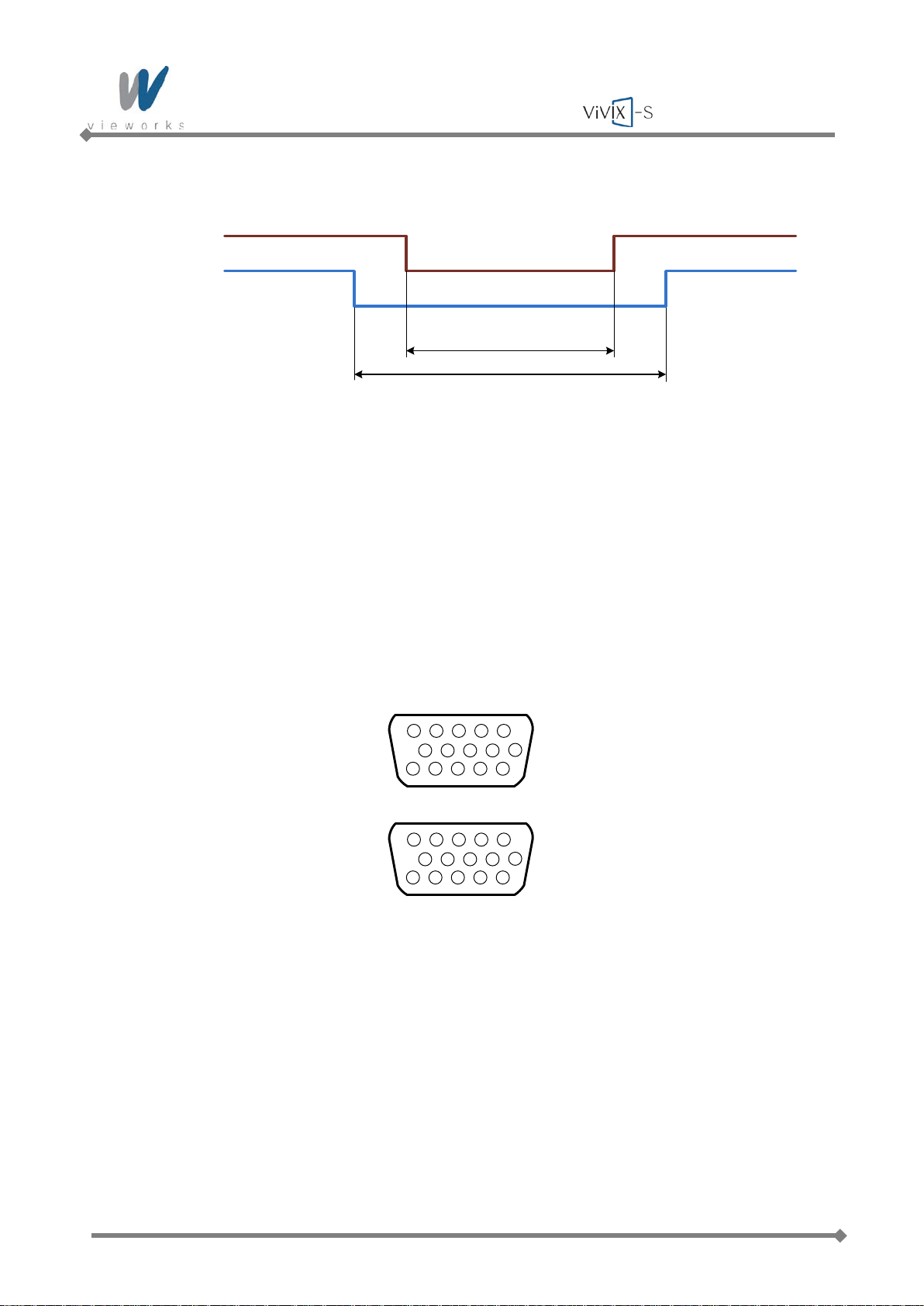
2.6.2 Timing of Signals (DR Trigger Mode)
Figure 2.12 Timing of Exposure signal
Image Acquisition Time+
Exposure request signal A (EXP_REQ) should be applied first, then exposure respond signal B
(EXP_OK).
Image Acquisition Time can be set from 40 ㎳ to 4,000 ㎳ with 1 ㎳ increment when default value
is 500 ㎳.
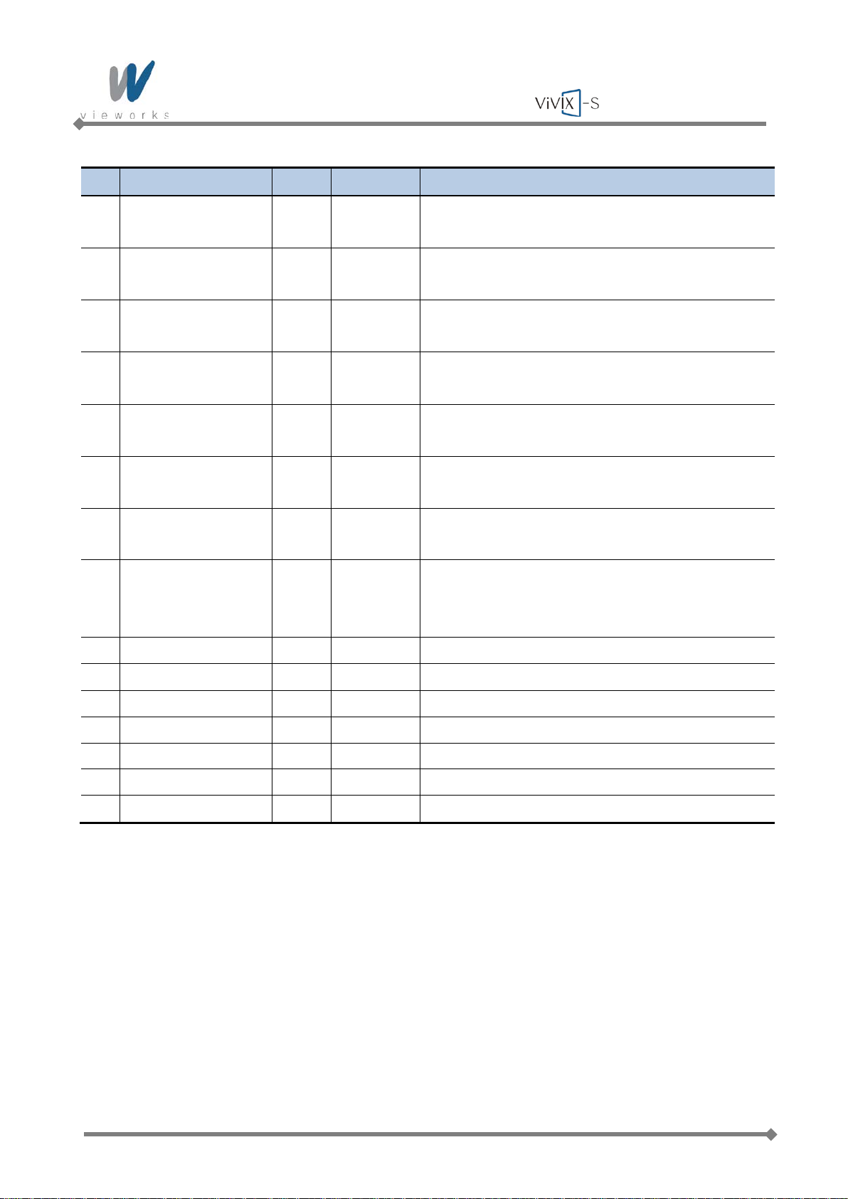
2.6.3 EXT_INF Port Pin Assignment
Figure 2.13 EXT_INF port pin assignments
Page 40 of 124 RA14-11A-022
Page 41
Wireless Service Manual
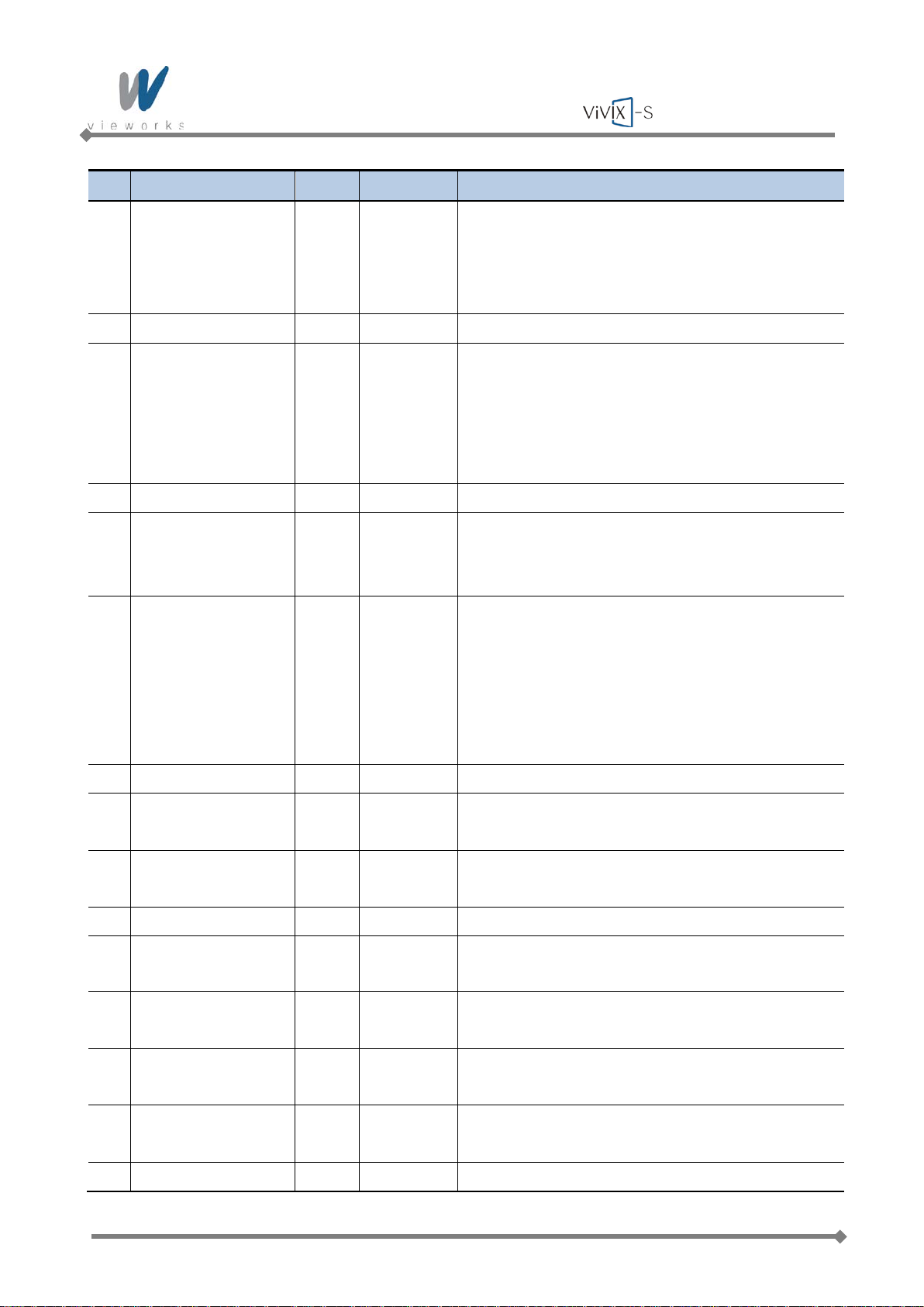
No. Signal Name I/O Color Description
Detector receives signal that X-ray generator is
1 EXP_REQ+_A Input Red
prepared to generate X-rays.
Contact Type – On: Closed, Off: Open
For the 1st DR Interface of Generator
2 EXP_REQ-_A Input Black Return signal from EXP_REQ+_A.
Detector receives signal that X-ray generator is
prepared to generate X-rays.
3 EXP_REQ_TTL_A Input Orange
TTL (Voltage) Ty pe – On: VCC, Off: GND
Current (5 ㎃ ~ 10 ㎃), Voltage (12 V ~ 24 V)
For the 1st DR Interface of Generator
4 EXP_REQ_GND_A Input Gray Return signal from EXP_REQ_TTL_A
Power of TTL signal coming from X-ray generator
5 EXP_OK_POWER_A Input Yellow
This is for the 1st DR Interface of Generator, but
it can be shared with the 2nd DR Interface.
Detector responds to X-ray generator about X-
ray generation.
The X-ray generator generates X-rays according
6 EXP_OK+_A Output Green
to this signal and then the detector performs Xray image acquiring.
For the 1st DR Interface of Generator
7 EXP_OK-_A Output Brown Return signal from EXP_OK+_A
8
Same as “EXP_OK+_A” for the 2nd DR Interface of
EXP_OK+_B Output Blue
Generator.
9
Same as “EXP_OK-_A” for the 2nd DR Interface of
EXP_OK-_B Output Pink
Generator.
10 Reserved - - Do not connect. Reserved for testing.
11
Same as “EXP_REQ+_A” for the 2nd DR Interface of
EXP_REQ+_B Input White
Generator.
12
Same as “EXP_REQ-_A” for the 2nd DR I nterface of
EXP_REQ-_B Input Purple
Generator.
13
Same as “EXP_REQ_TTL_A” for the 2nd DR
EXP_REQ_TTL_B Input White/Red
Interface of Generator.
14
Same as “EXP_REQ_GND_A” for the 2nd DR
EXP_REQ_GND_B Input White/Black
Interface of Generator.
15 Reserved - - Do not connect. Reserved for testing.
Tab le 2.10 EXT_INF1 port pin description (1 ~ 15)
Page 41 of 124 RA14-11A-022
Page 42
Wireless Service Manual
No. Signal Name I/O Color Description
16 EXP_REQ+_C Input Red
17 EXP_REQ-_C Input Black
18 EXP_REQ_TTL_C Input Orange
19
EXP_REQ_GND_C Input Gray
20
EXP_OK_POWER_C Input Yellow
21
EXP_OK+_C Output Green
22
EXP_OK-_C Output Brown
23 EXT_A+ Input -
Same as “EXP_ REQ+_A” for the 3rd DR Interface of
Generator.
Same as “EXP_ REQ -_A” f or the 3rd DR Int erface of
Generator.
Same as “EXP_REQ_TTL_A” for the 3rd DR
Interface of Generator.
Same as “EXP_REQ_GND_A” for the 3rd DR
Interface of Generator.
Same as “EXP_OK_POWER _A” for the 3rd DR
Interface of Generator.
Same as “EXP_OK+_A” for the 3rd DR Interface of
Generator.
Same as “EXP_OK-_A” for the 3rd DR Interface of
Generator.
Detector receives the 1st status signal that it is
equipped on/in the table or in the wall stand.
Contact Type – On: Closed, Off: Open
24 EXT_A- Input - Return signal from EXT_A+
25 EXT_B+ Input - Same as “EXT_A+” for the 2nd status signal
26 EXT_B- Input - Same as “EXT_A-” for the 2nd status signal
27 EXT_C+ Input - Same as “EXT_A+” for the 3rd status signal
28 EXT_C- Input - Same as “EXT_A-” for the 3rd status signal
29 EXT_D+ Input - Same as “EXT_A+” for the 4th status signal
30 EXT_D- Input - Same as “EXT_A-” for the 4th status signal
Tab le 2.11 EXT_INF2 port pin description (16 ~ 30)
Page 42 of 124 RA14-11A-022
Page 43
Wireless Service Manual
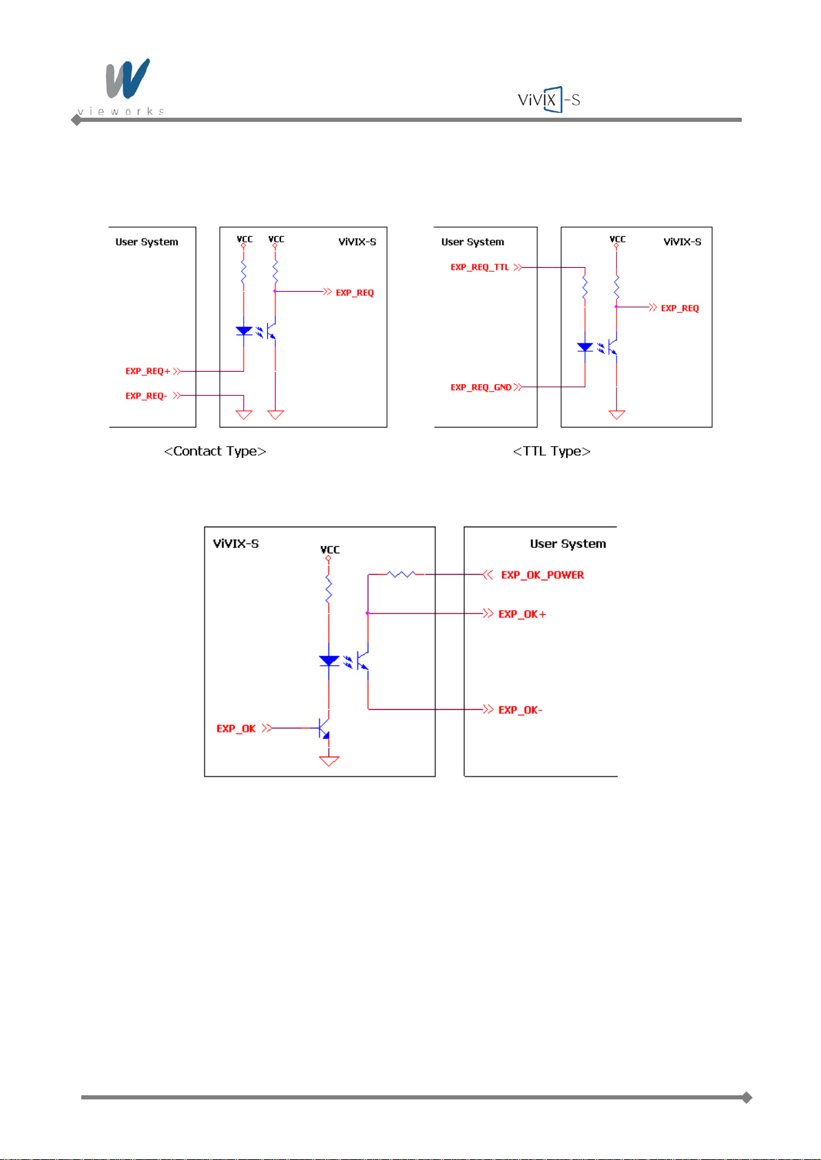
2.6.4 Input and Output Circuits
The following diagrams describe exposure request and exposure OK circuits.
Figure 2.14 Exposure Request Input Circuit
Figure 2.15 Exposure Respond Output Circuit
Page 43 of 124 RA14-11A-022
Page 44
Wireless Service Manual
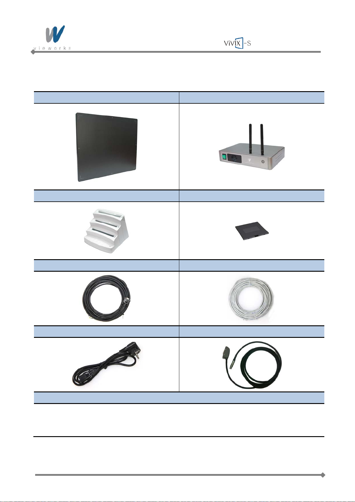
3. Packaging and Contents
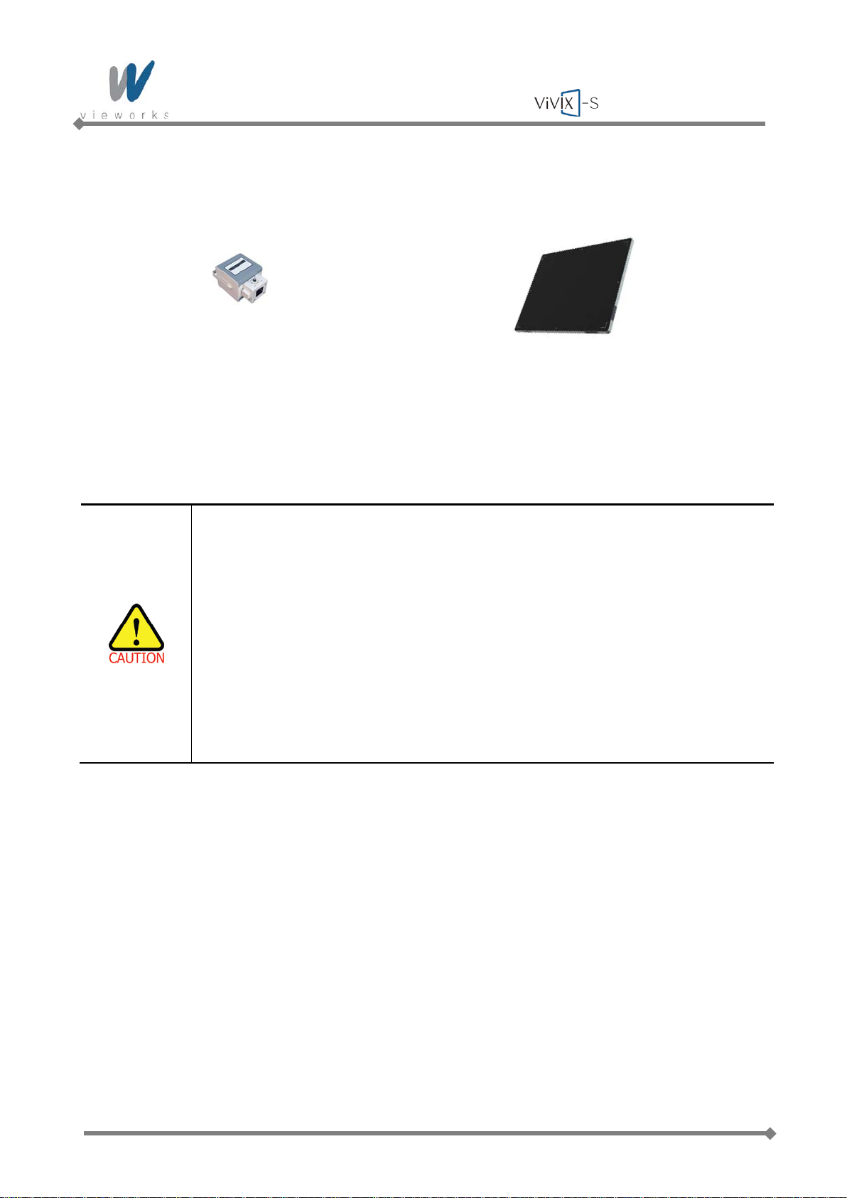
Detector (FXRD-1417WA/B) System Control Unit (FXRS-03A)
Battery Charger Battery Pack
Generator Interface Cable (15M) LAN Cable (Gigabit LAN, 15M)
AC Powe r Cable Tether Interface
Installation Software CD
Viewer: VXvue
Calibration SW: VXSetup
Calibration Data
Tab le 3.1 ViVIX-S Wireless Packaging
Page 44 of 124 RA14-11A-022
Page 45
Wireless Service Manual
4. How to Install
4.1 Hardware Installation
This section describes how to connect the flat panel imaging system (detector) whose model name is FXRD1417WA(B).
Installation of this equipment should be made by licensed and authorized personnel.
4.1.1 FXRD-1417WA (B)
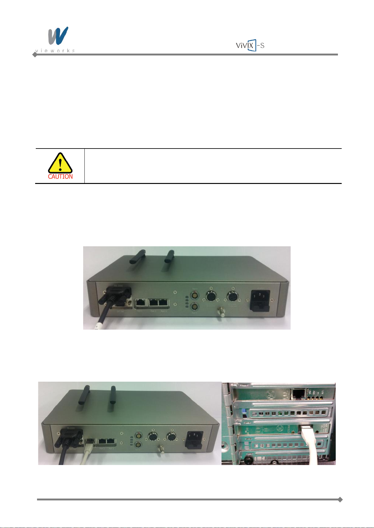
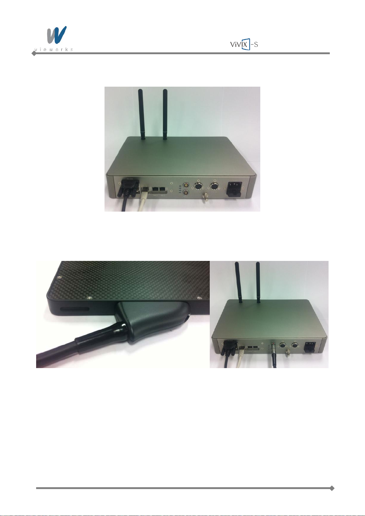
1 Connect the one end of the generator interface cable to the EXT_INF port of SCU, and the other to the
port of the X-ray generator.
2 Connect the one end of the LAN cable to Port 1 of SCU, and the other to the LAN Card Connector of
workstation assigned for the Data Transfer.
Page 45 of 124 RA14-11A-022
Page 46
Wireless Service Manual
3 Make an antenna of SCU stand upright.
4 To transmit image data using Tether Interface, connect the one end of the Tether Interface cable to
Port 4 or Port 5 of SCU.
Page 46 of 124 RA14-11A-022
Page 47
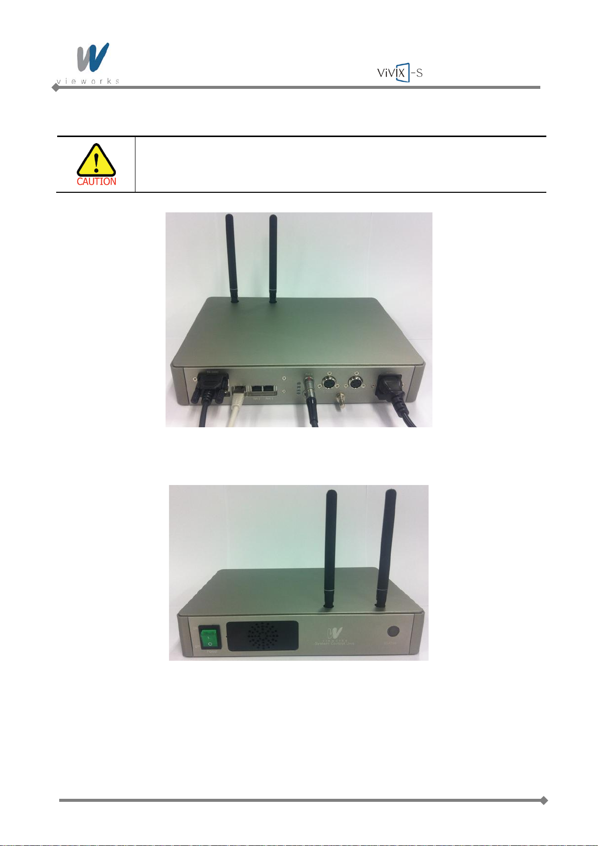
Wireless Service Manual
5 Connect the power cable to the AC port of the SCU to supply power.
This equipment must only be connected to a supply mains with protective earth.
6 Turn on the power switch in front of the SCU.
Page 47 of 124 RA14-11A-022
Page 48
Wireless Service Manual
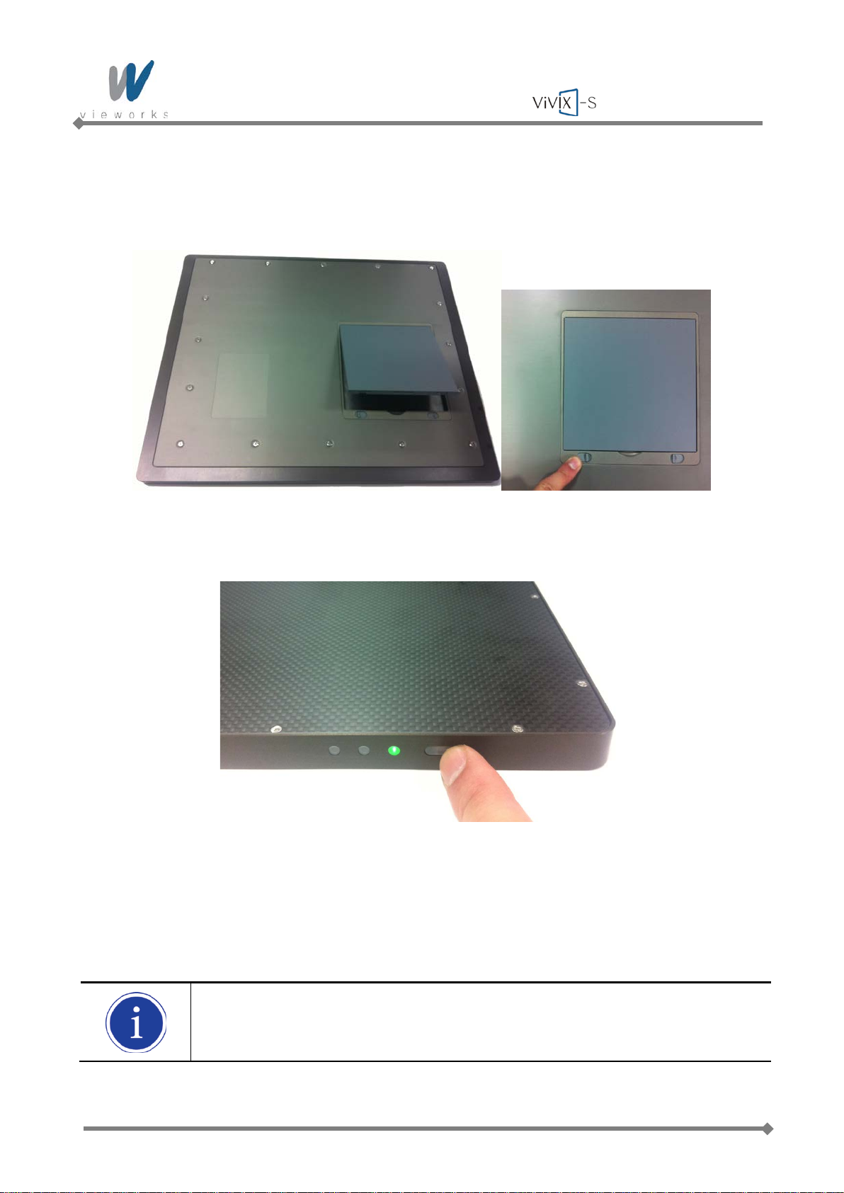
7 Attach a fully charged battery pack to the detector. To attach the battery pack, slide the battery pack into
the battery compartment of the detector. Make sure that the claws on the battery pack are aligned with
the groove on the battery compartment. Slide the battery lock lever until it clicks into place.
8 Press and hold the power button of the detector for 3 seconds to turn on the detector.
9 When you have finished using the detector, press and hold the power button for 3 seconds to turn off
the detector. Remove the battery pack if the detector will not be used for some time. To remove the
battery pack, slide the battery lock lever to release it, put your fingers on the battery compartment
groove that lifts up, and then pull out the battery pack.
When the detector is not be used for some time, remove the battery pack. Otherwise, over
discharge may occur, resulting in shortened battery life.
Page 48 of 124 RA14-11A-022
Page 49
Wireless Service Manual
4.2 Software Installation
4.2.1 Intel Gigabit Controller Driver Installation and Setting
Before installing Intel Gigabit Controller Driver, make sure your Ethernet Card is properly
installed on the workstation.
The recommended Ethernet Card is Intel
supporting 1 Gbps or above is available.
Gigabit LAN card must support the following requirements.
[Jumbo Frames: 9014 Byte], [Receive Descriptors: 2048]
This is not a component of ViVIX-S but recommend component. So, you have to use
installation package designed for your Gigabit Controller.
1~8 steps may differ according to Gigabit Controller to use.
Following procedures are provided as an example to refer to.
®
Gigabit CT or later. And also, Ethernet Card
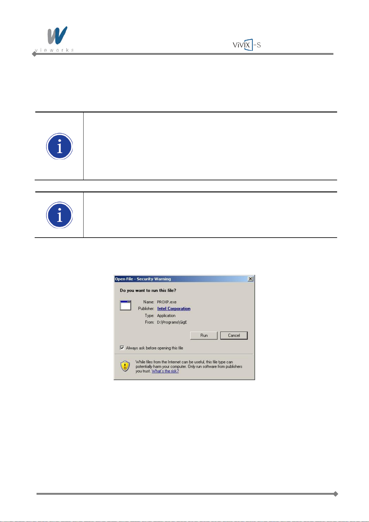
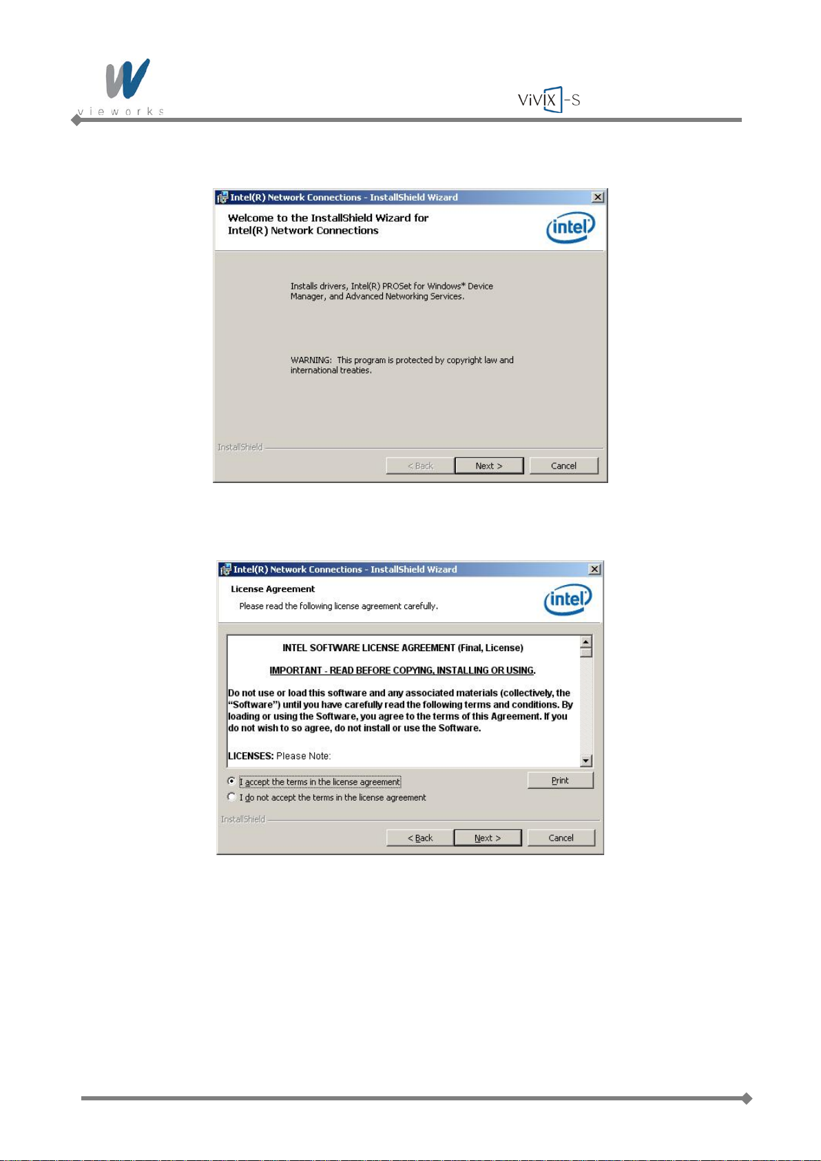
1 Click PRO XP.e x e to start InstallShield Wizard, and then click the Run button.
Page 49 of 124 RA14-11A-022
Page 50
Wireless Service Manual
2 Click the Next button.
3 Accept the license agreement and click the Next button.
Page 50 of 124 RA14-11A-022
Page 51
Wireless Service Manual
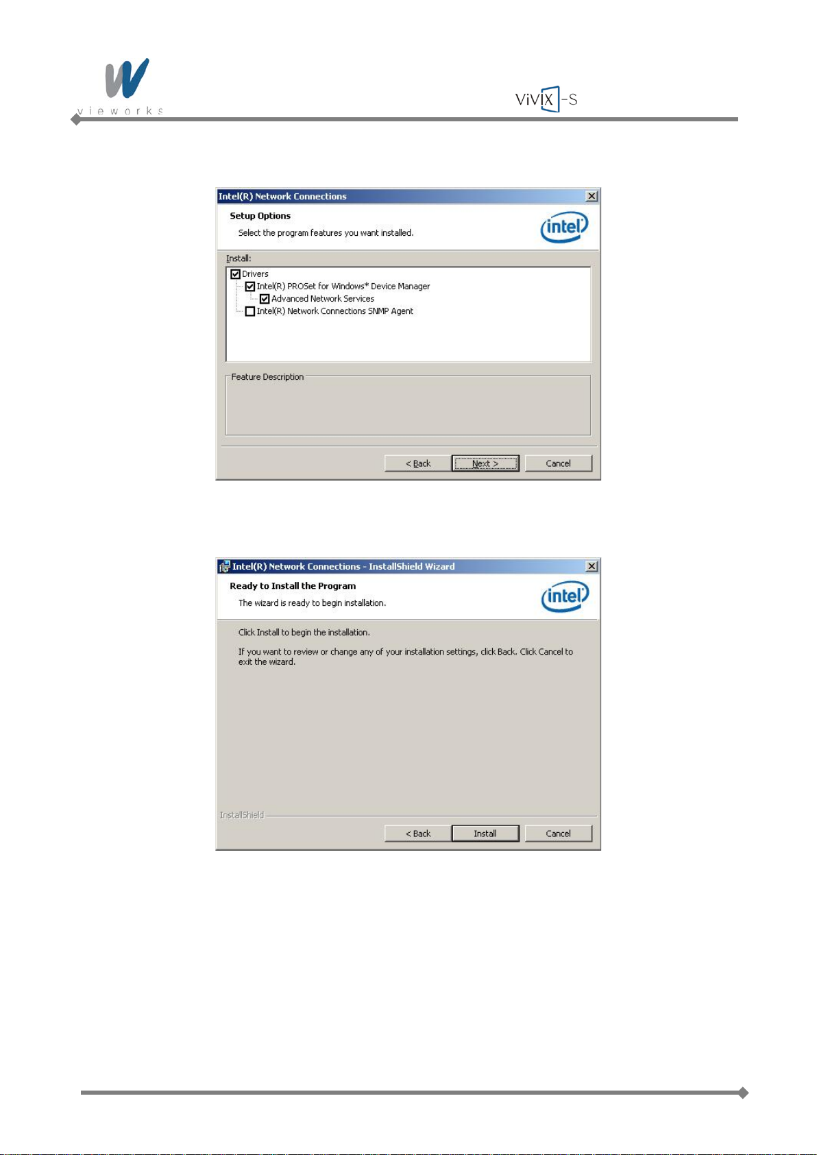
4 Select the components to install and click the Next button.
5 Click the Install button.
Page 51 of 124 RA14-11A-022
Page 52
Wireless Service Manual
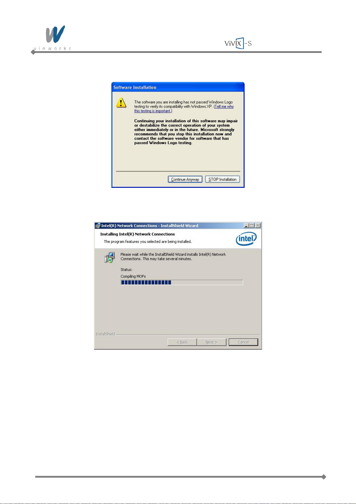
6 When the following message appears, click the Continue Anyway button.
7 Installation status bar appears in Installing Intel® Network Connections dialog box.
Page 52 of 124 RA14-11A-022
Page 53
Wireless Service Manual
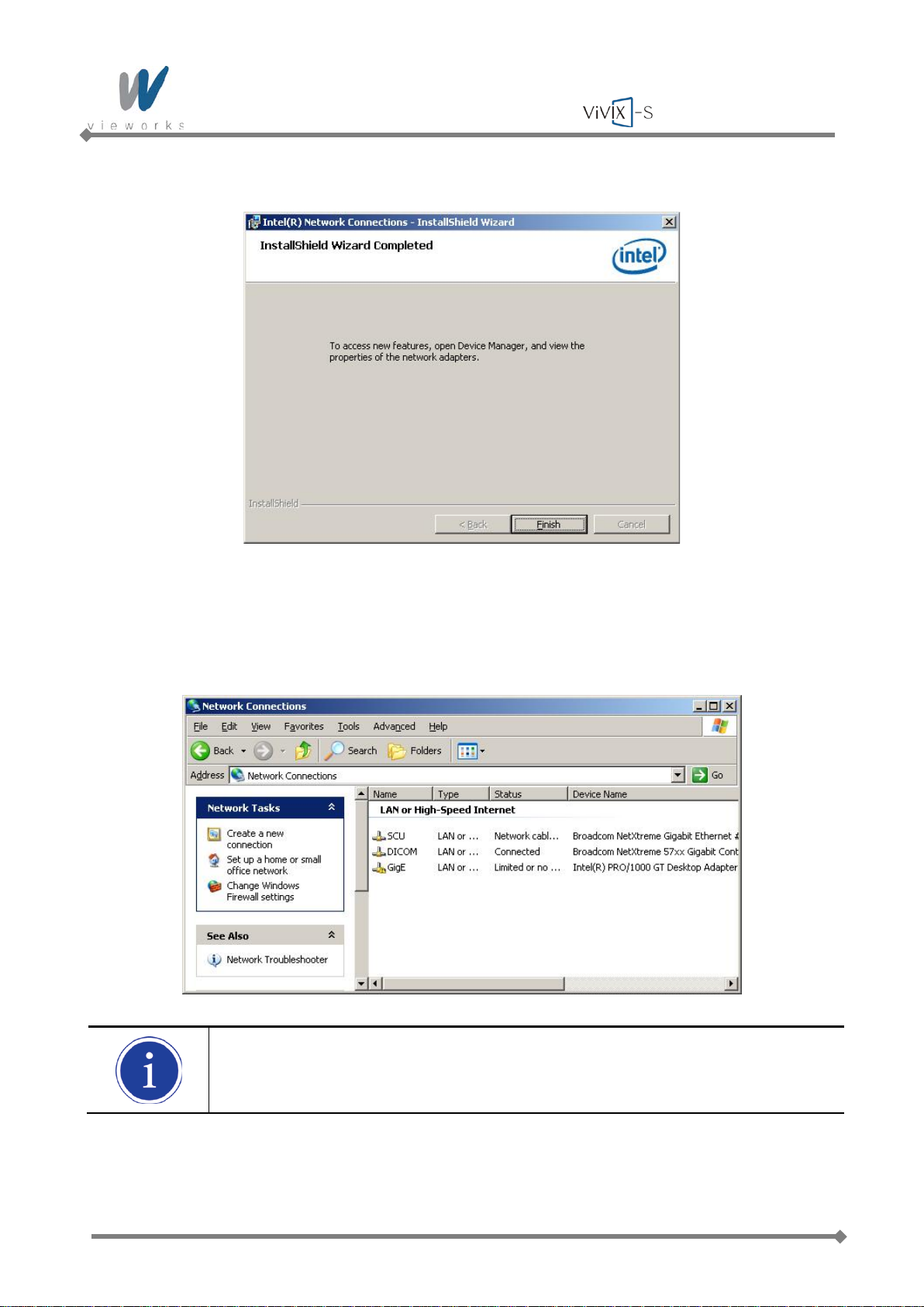
8 Click the Finish button.
4.2.2 Gigabit Controller Se t ti ng on Windows XP
1 Click Start > Setting > Control Panel > Network Connections to open the Network Connections
dialog box, and then rename Local Area Connection with GigE.
It is not necessary to change name with GigE. It just distinguishes between that
connection and other connections .
2 Right-click the GigE and then click the Properties.
Page 53 of 124 RA14-11A-022
Page 54
Wireless Service Manual
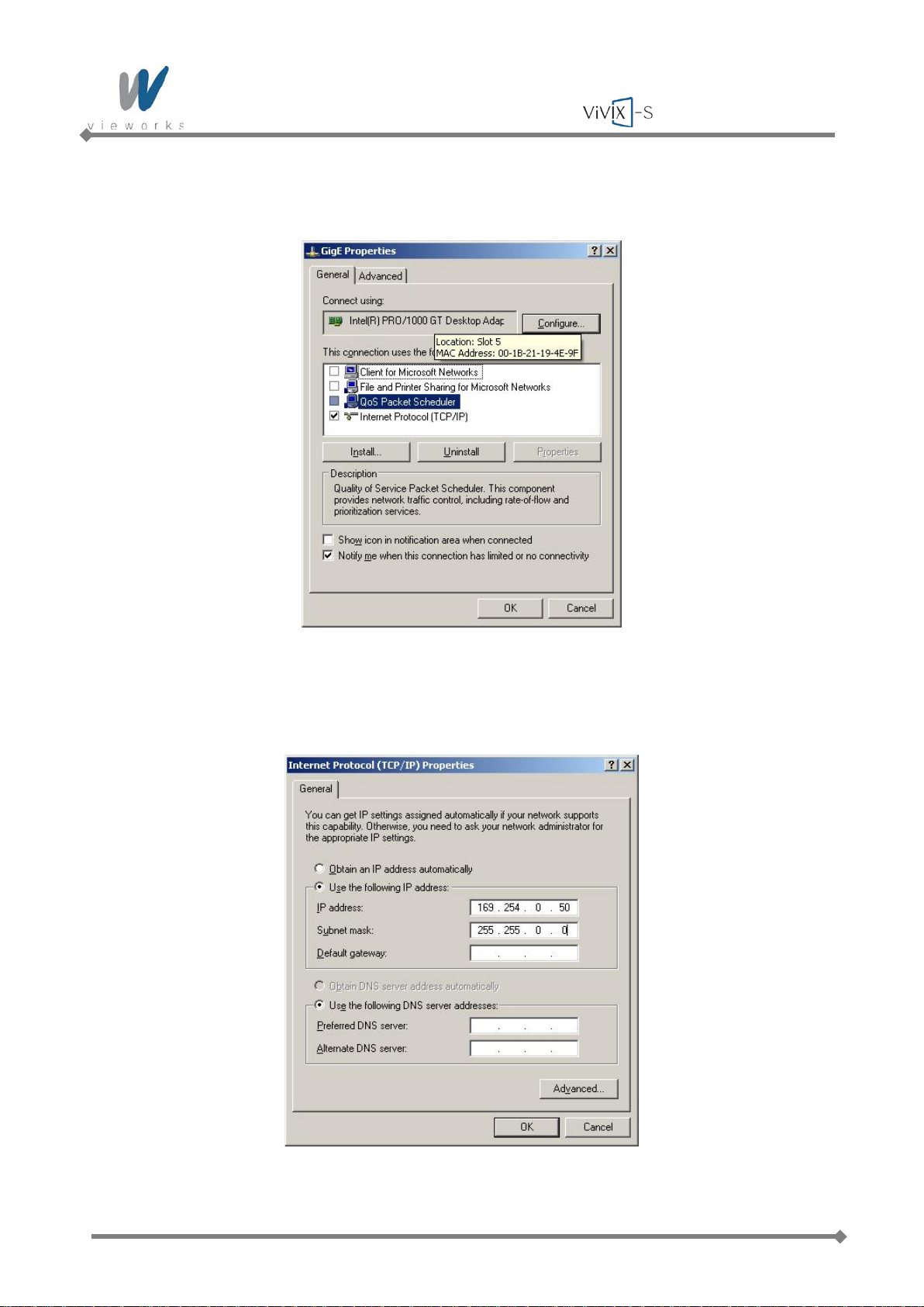
3 Uncheck all checkboxes except Vieworks Image Filter Driver or GigaLinx Image Filter Driver and
Internet Protocol [TCP/IP].
4 Click the Internet Protocol [TCP/IP] and set the IP as shown below, and then click the Advanced
button.
Page 54 of 124 RA14-11A-022
Page 55
Wireless Service Manual
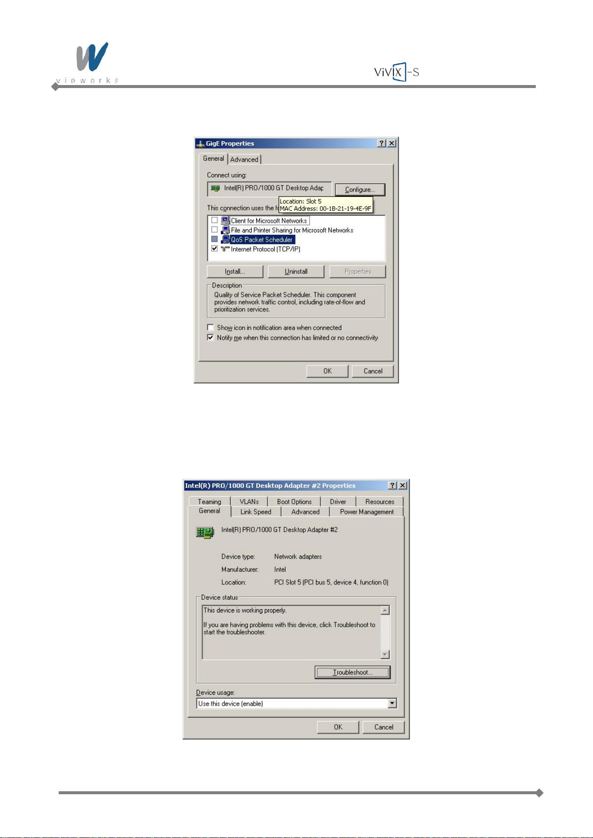
5 Click the OK button to close the dialog box.
6 Click Start > Setting > Control Panel > Network Connections to open the Network Connections
dialog box, and right-click GigE, and then click Properties to open the GigE Prop ert ies dialog box.
Click the Configure button to open the following dialog box, and then go to the Advanced tab.
Page 55 of 124 RA14-11A-022
Page 56
Wireless Service Manual
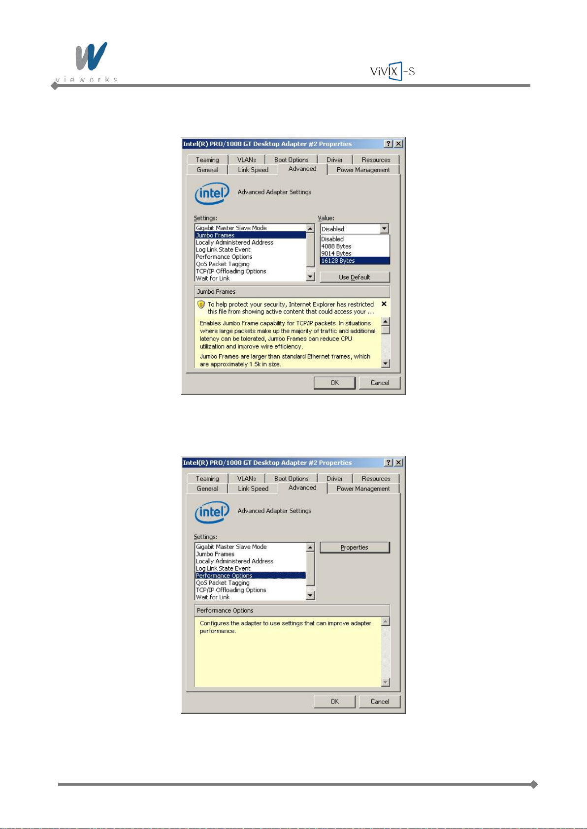
7 Set the Jumbo Frames to the maximum value.
8 Choose Performance Options in the list of Settings and click the Properties button on the right.
Page 56 of 124 RA14-11A-022
Page 57
Wireless Service Manual
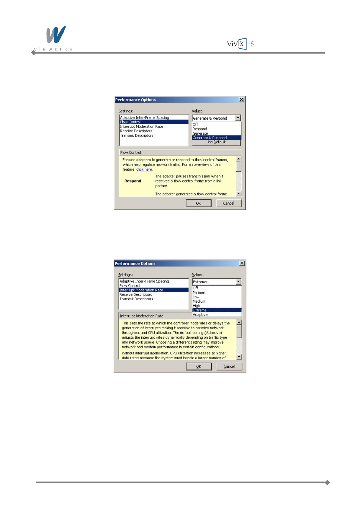
9 Choose Flow Control in the list of Settings and Generate & Respond in the list of Value as shown
below.
10 Choose Interrupt Moderation Rate in the list of Settings and Extreme in the list of Value as shown
below.
Page 57 of 124 RA14-11A-022
Page 58
Wireless Service Manual
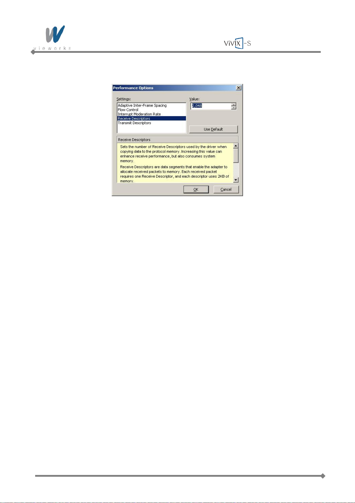
11 Choose Receive Descriptors and set to the maximum value.
12 Click the OK button.
Page 58 of 124 RA14-11A-022
Page 59
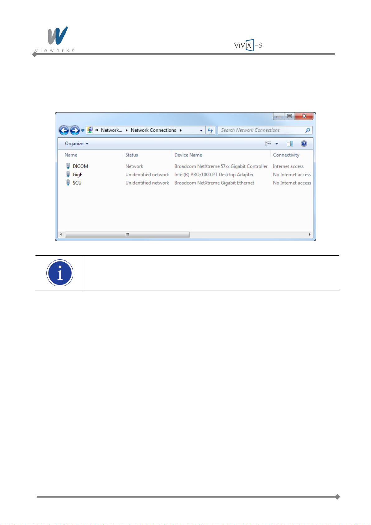
Wireless Service Manual
4.2.3 Gigabit Controller Se t ti ng on Windows 7
1 Click Start > Control Panel > Network and Internet > Network and Sharing Center > Change
Adapter Setting and then rename Local Area Connection with GigE.
It is not necessary to change name with GigE. It just distinguishes between that
connection and other connections.
2 Right-click the GigE and then click the Properties.
Page 59 of 124 RA14-11A-022
Page 60
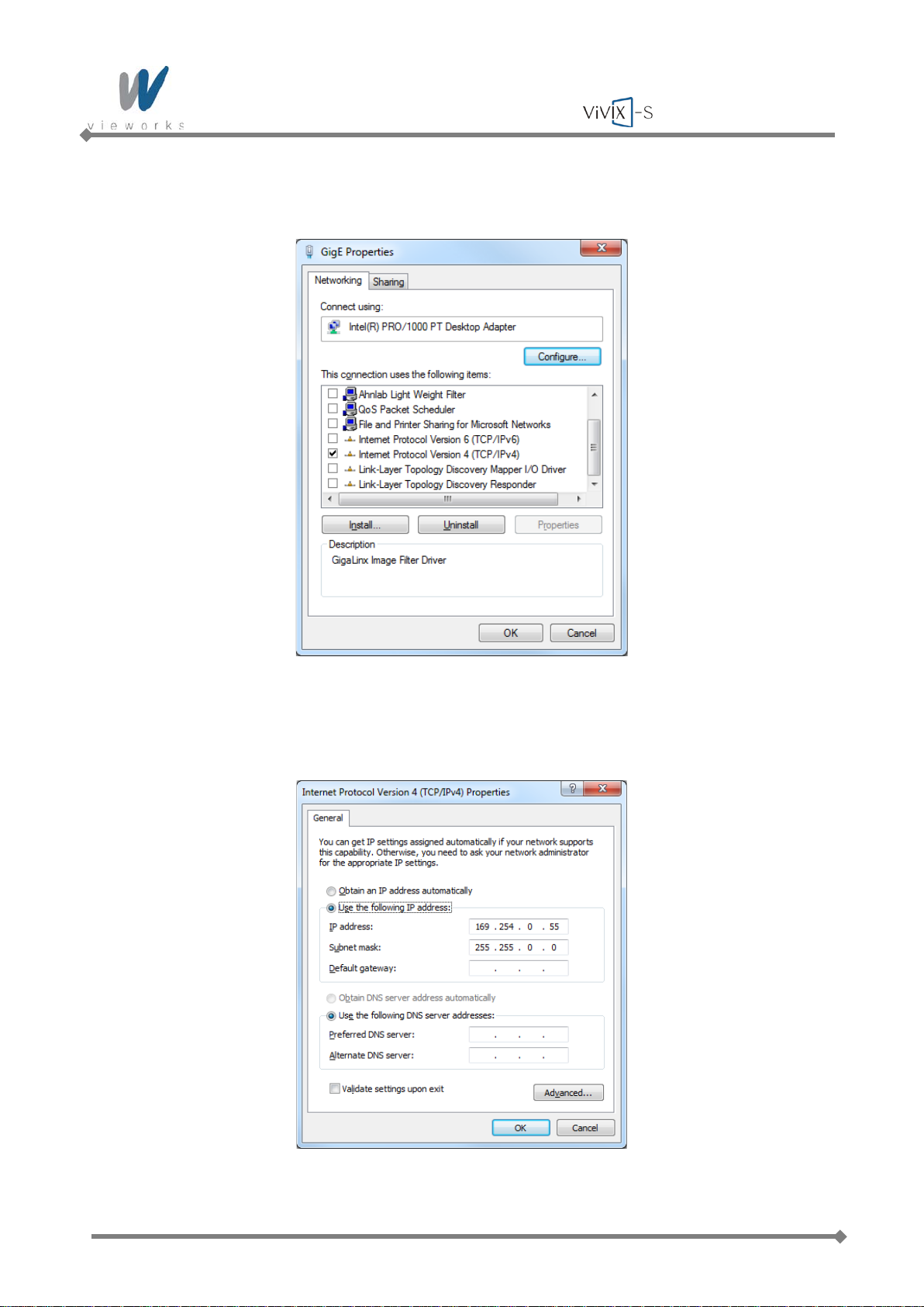
Wireless Service Manual
3 Uncheck all checkboxes except Vieworks Image Filter Driver or GigaLinx Image Filter Driver and
Internet Protocol [TCP/IP].
4 Click the Internet Protocol [TCP/IP] and set the IP as shown below, and then click the Advanced
button.
Page 60 of 124 RA14-11A-022
Page 61
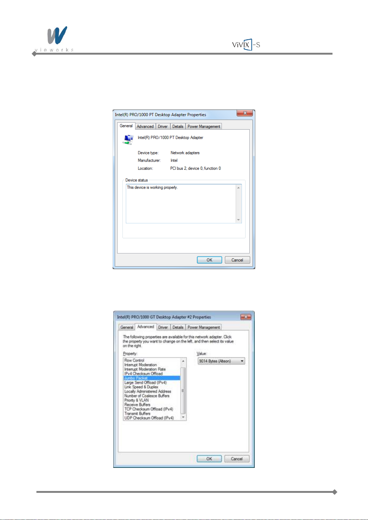
Wireless Service Manual
5 Click Start > Control Panel > Network and Internet > Network and Sharing Center > Change
Adapter Setting, right-click GigE, and then click Properties to open the GigE Properties dialog box.
Click the Configure button to open the following dialog box, and then go to the Advanced tab.
6 Set the Jumbo Packet to the maximum value.
Page 61 of 124 RA14-11A-022
Page 62
Wireless Service Manual
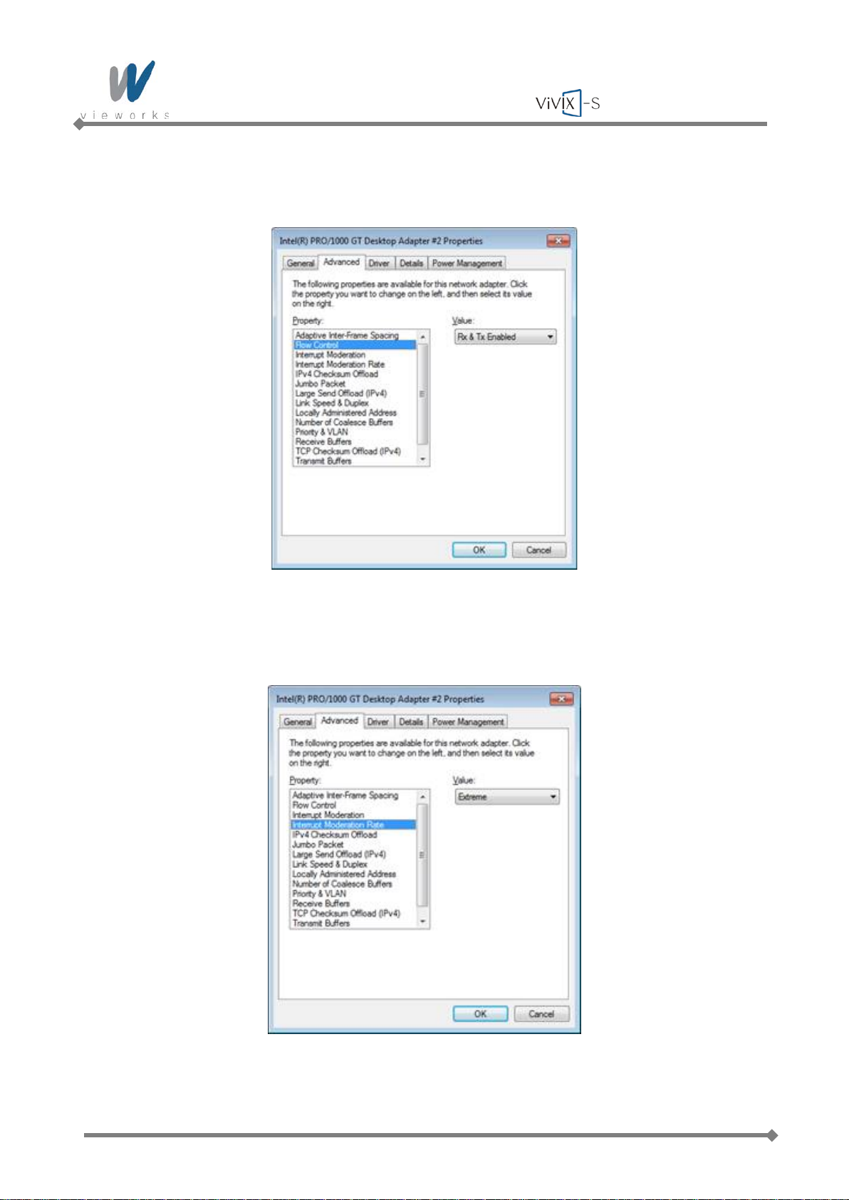
7 Choose Flow Control in the list of Property and select Rx & Tx Enabled in the list of Value as shown
below.
8 Choose Interrupt Moderation Rate in the list of Property and Extreme in the list of Value as shown
below.
Page 62 of 124 RA14-11A-022
Page 63
Wireless Service Manual
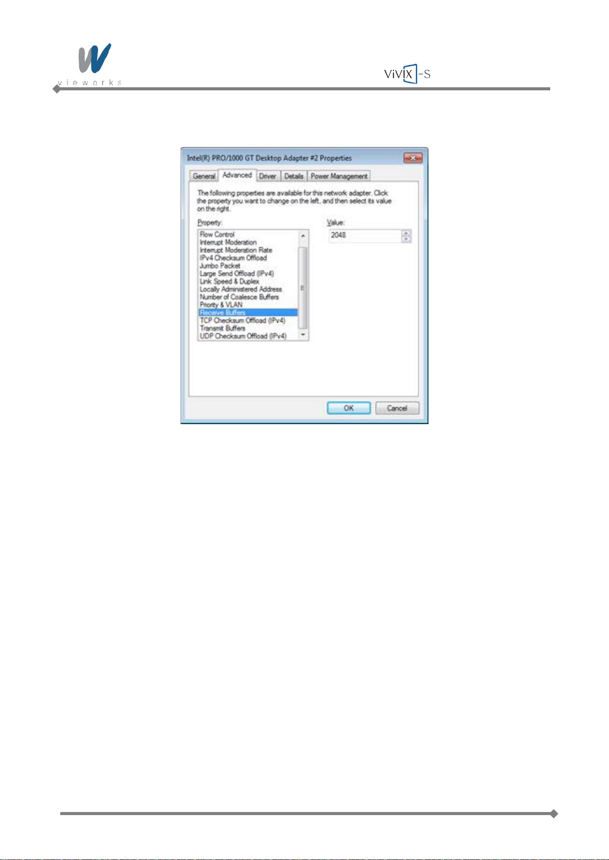
9 Choose Receive Buffers and set to the maximum value.
10 Click the OK button.
Page 63 of 124 RA14-11A-022
Page 64
Wireless Service Manual
4.2.4 VXvue Installation
User must follow instructions below to protect against cyber security threats such as virus
and worms.
Prior to installing and using VXvue, scan the computer system with anti-virus
software to make sure the system is virus free.
Install, setup and enable adequate anti-virus software.
The operating system should be updated frequently to protect VXvue against harmful
activities.
If you have a cyber security problem, contact the manufacturer on the phone or by e-
mail referring to the contact information in this manual.
1 Insert the CD/DVD into the CD Drive.
2 Run Setup.exe.
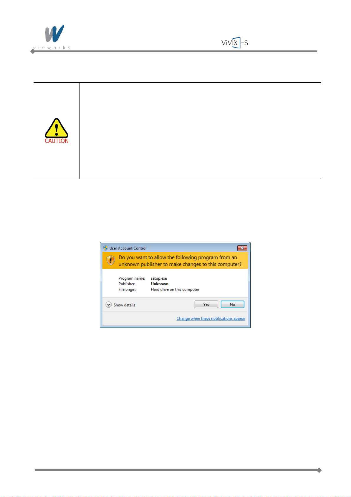
3 Click the Yes button when the following dialog appears. The dialog may not appear depending on your
Windows settings.
Page 64 of 124 RA14-11A-022
Page 65
Wireless Service Manual
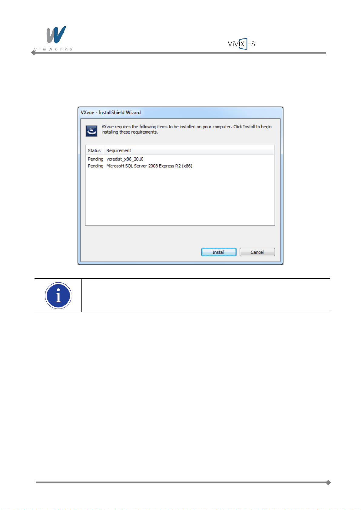
4 The prerequisites for VXvue installation are displayed in the VXvue – InstallShield Wizard dialog, then
click the Install button. The installation may take several minutes depending on your system
environment.
The items listed under the Requirement may from the above figure depending on your
system environment.
Page 65 of 124 RA14-11A-022
Page 66
Wireless Service Manual
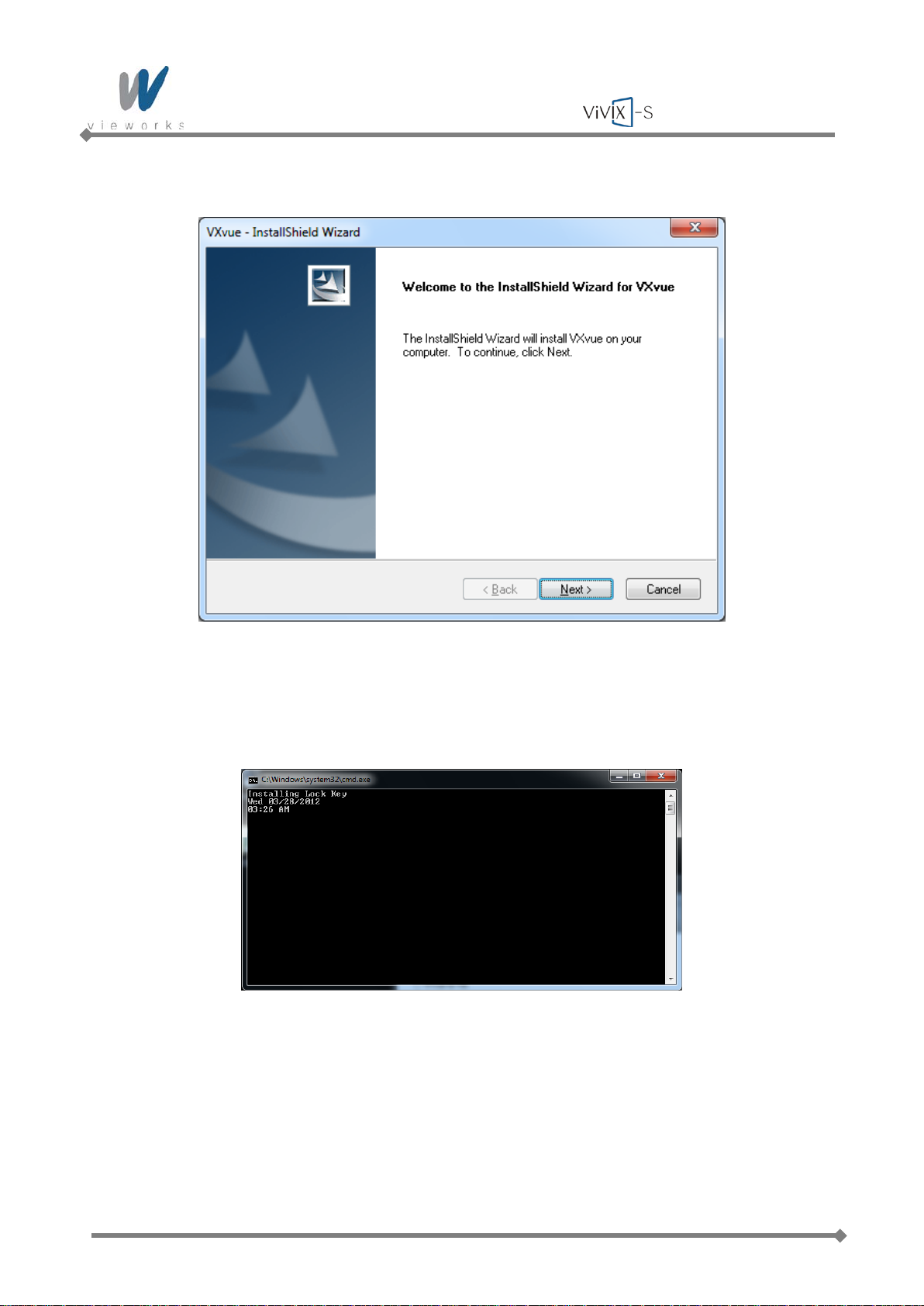
5 When the prerequisites for VXvue installation have been installed, click the Next button.
6 A driver for recognizing license hardware key will be installed on your system during setup process. If
the window installing the driver appears, do not close the window and wait for the installation to
complete.
Page 66 of 124 RA14-11A-022
Page 67
Wireless Service Manual
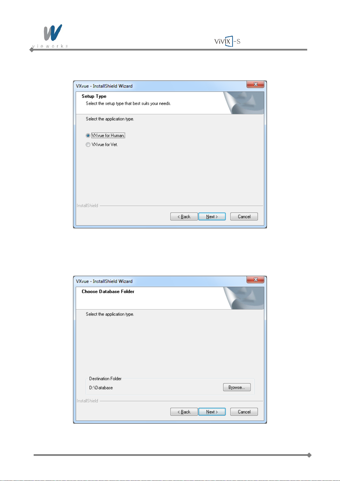
7 Choose the application type and click the Next button.
8 Choose the folder location where you want to save VXvue data. The default destination is D:\Database.
To change the folder location, click the Browse button to locate the folder.
Page 67 of 124 RA14-11A-022
Page 68
Wireless Service Manual
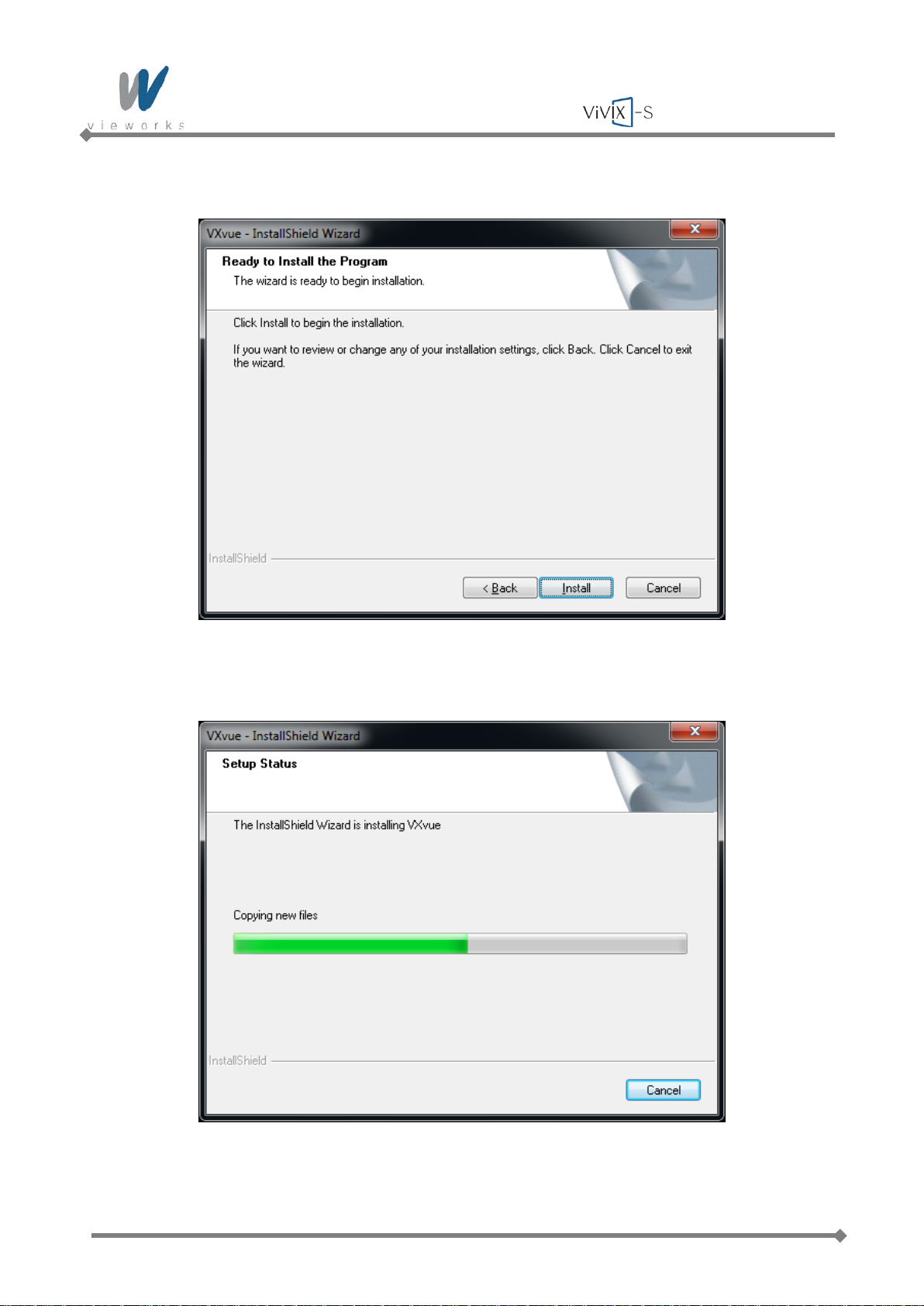
9 Click the Install button to begin VXvue installation.
10 The installation process will continue and a progress bar will be displayed in the Setup Status window.
Page 68 of 124 RA14-11A-022
Page 69
Wireless Service Manual
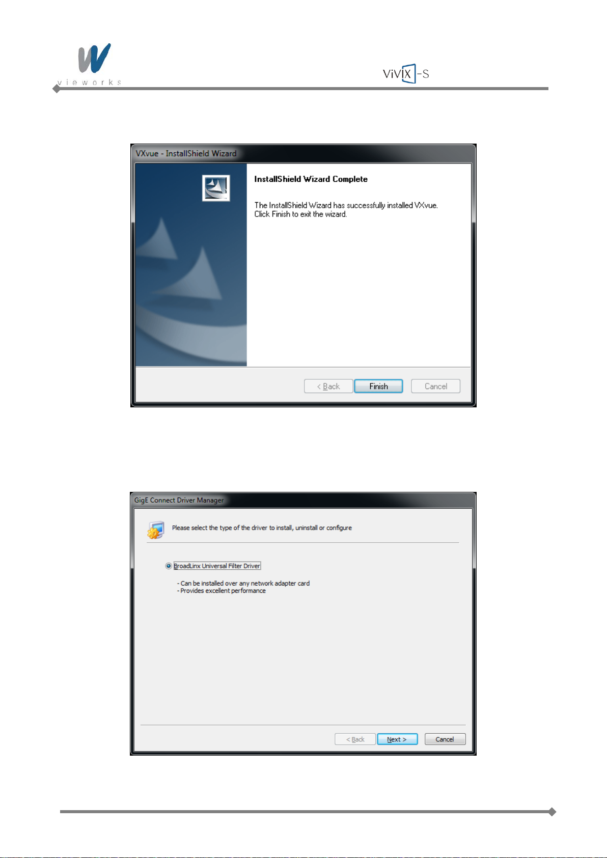
11 When the installation is complete, click the Finish button.
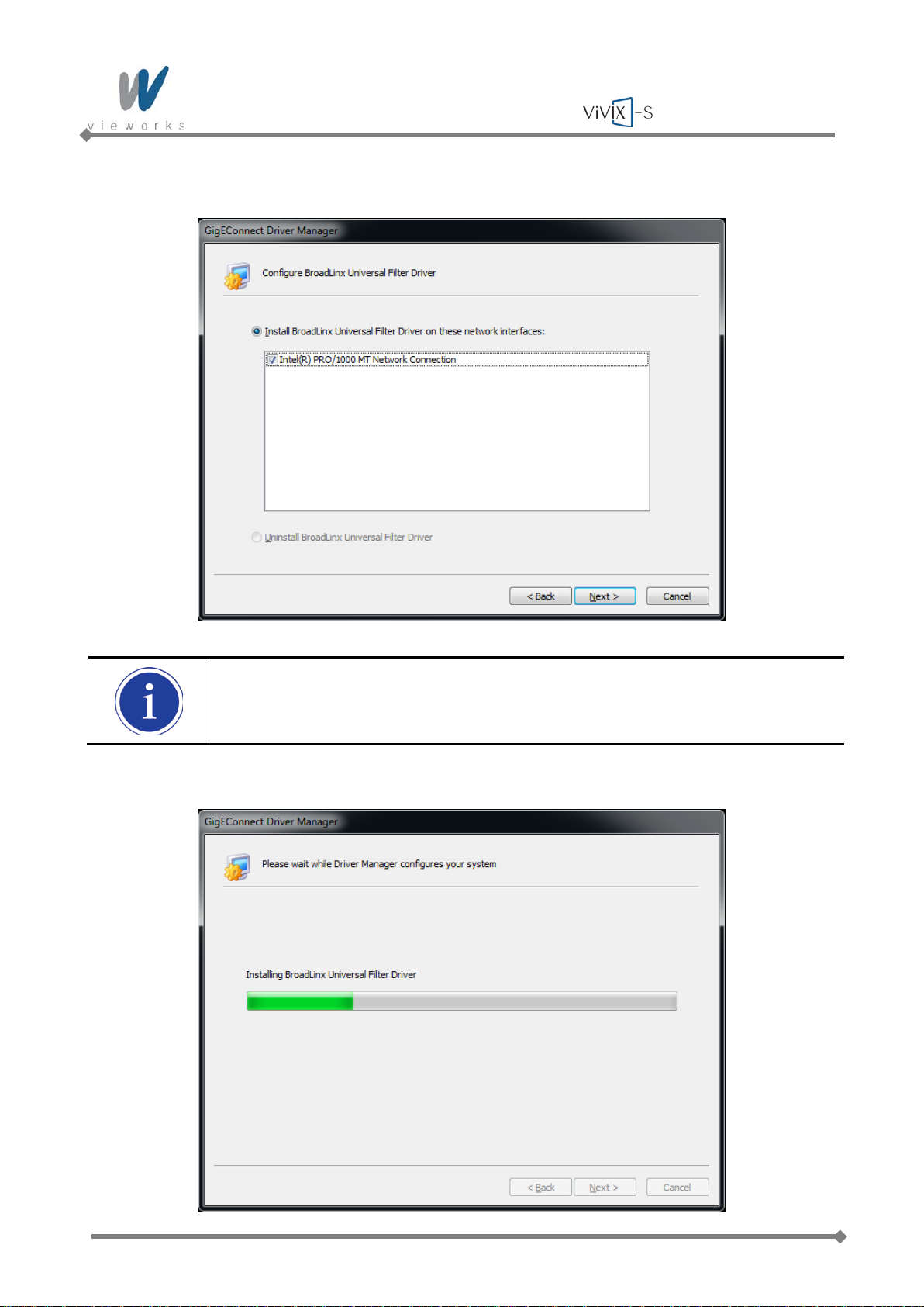
12 When Filter Driver installation dialog appears after installing VXvue, choose BroadLinx Universal Filter
Driver and click the Next button.
Page 69 of 124 RA14-11A-022
Page 70
Wireless Service Manual
13 Select the network interface card connected to SCU and click the Next button.
The above figure may vary depending on your system environment.
14 The progress of Filter Driver installation will be displayed.
Page 70 of 124 RA14-11A-022
Page 71
Wireless Service Manual
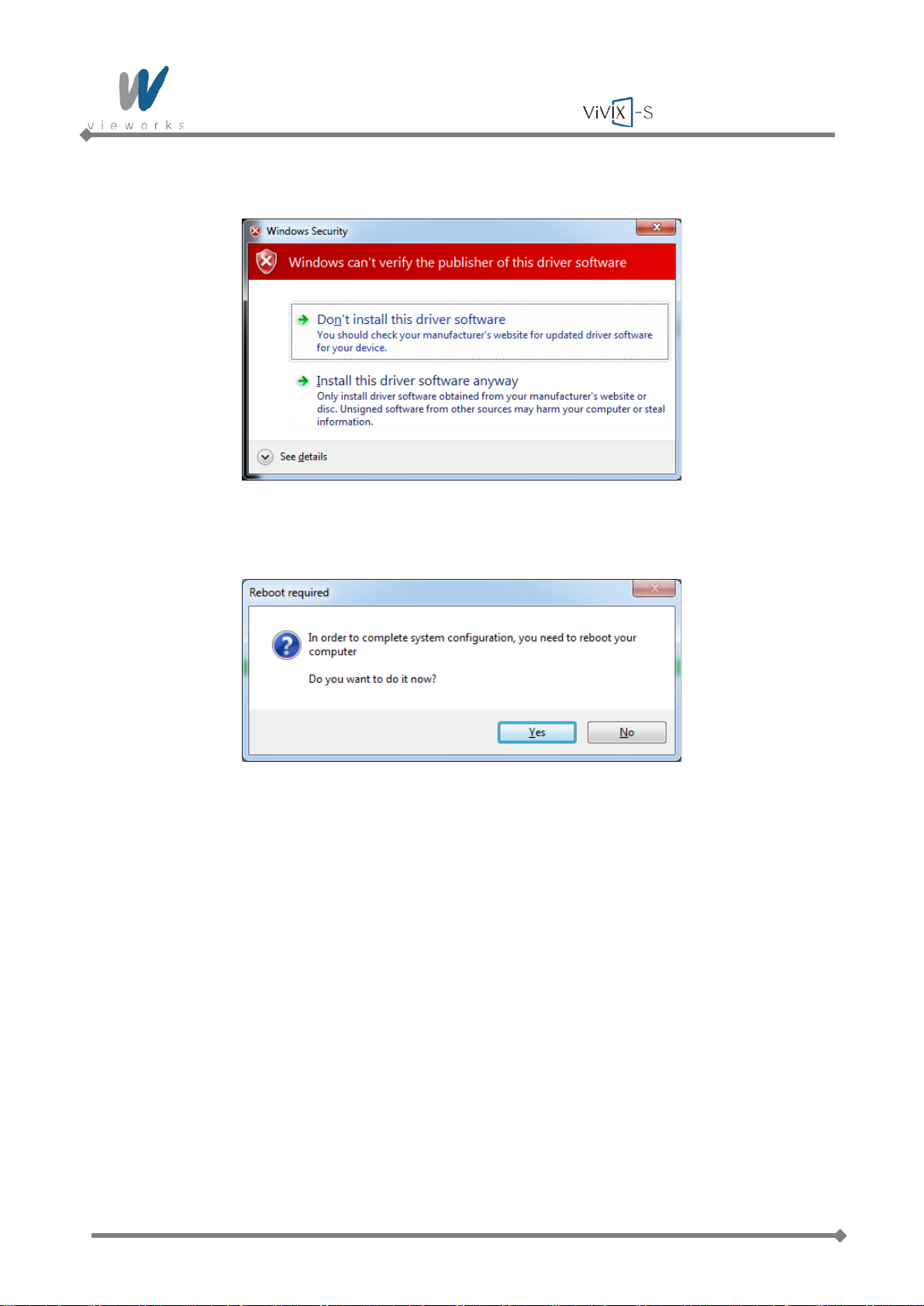
15 Click Install this driver software anyway when the following dialog appears.
16 After completing installation, click the Yes button to restart the computer.
17 Now the VXvue software and data are successfully installed in each directory as shown below.
Software: C:\program files\VXvue
Image and other data: D:\Database or user defined folder
Executable File
- VXvue.exe: Image Viewer
- VXSetup.exe: Calibration Software
Page 71 of 124 RA14-11A-022
Page 72
Wireless Service Manual
4.2.5 Allowing VXvue to communicate through Windows Firewall on
Windows XP
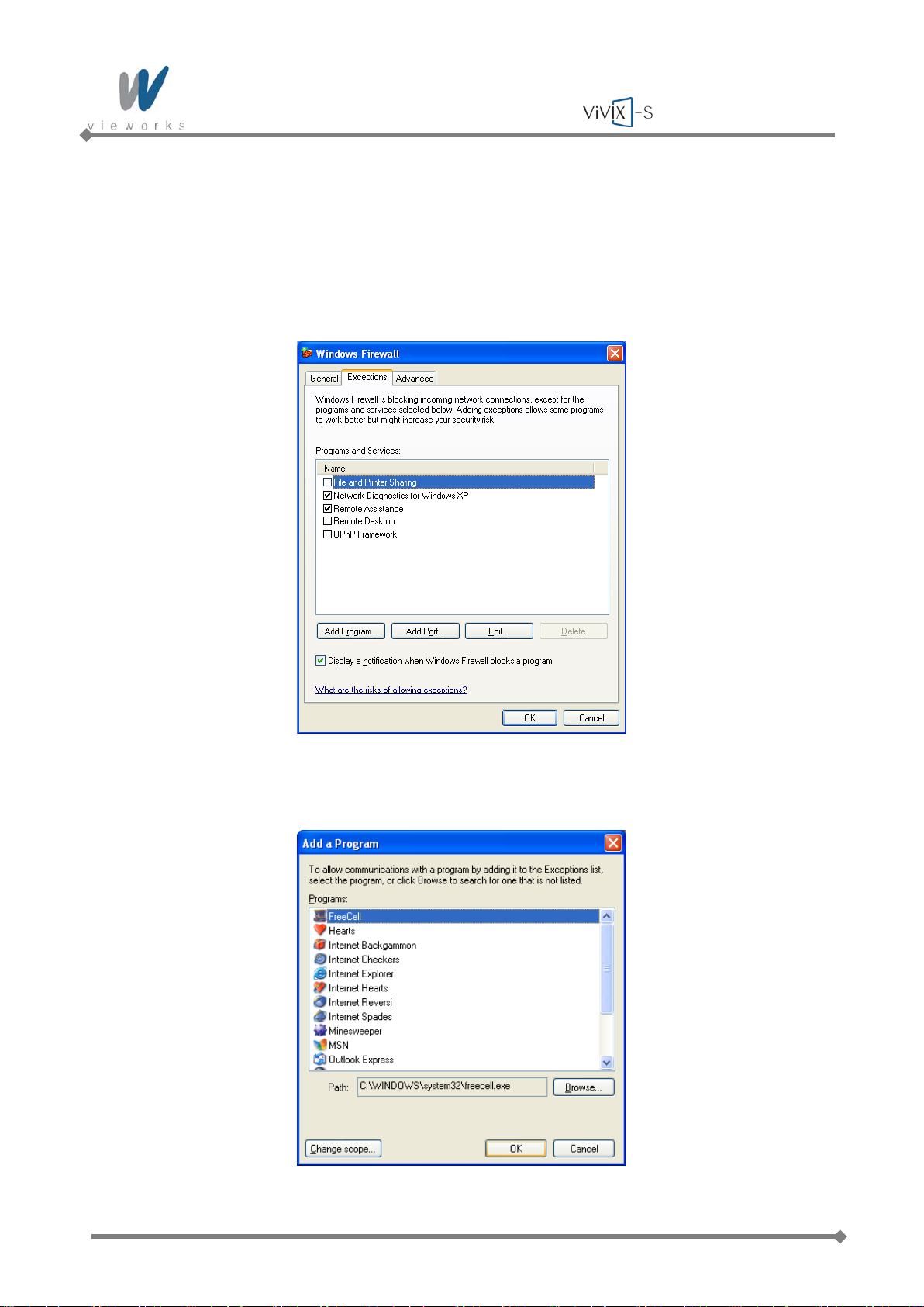
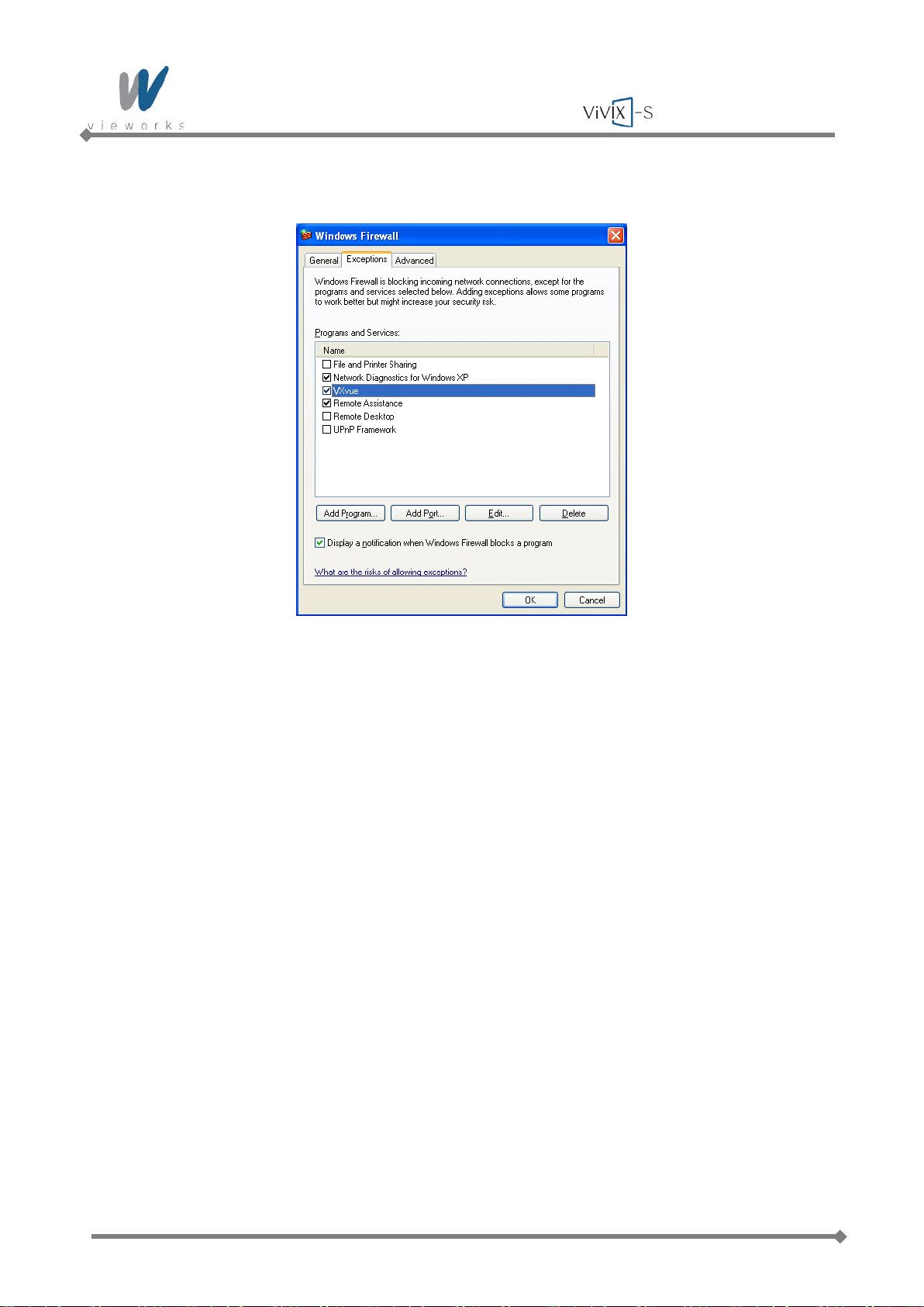
1 Click Start > Setting > Control Panel > Windows Firewall and then click the Exceptions tab.
2 Click the Add Program… button.
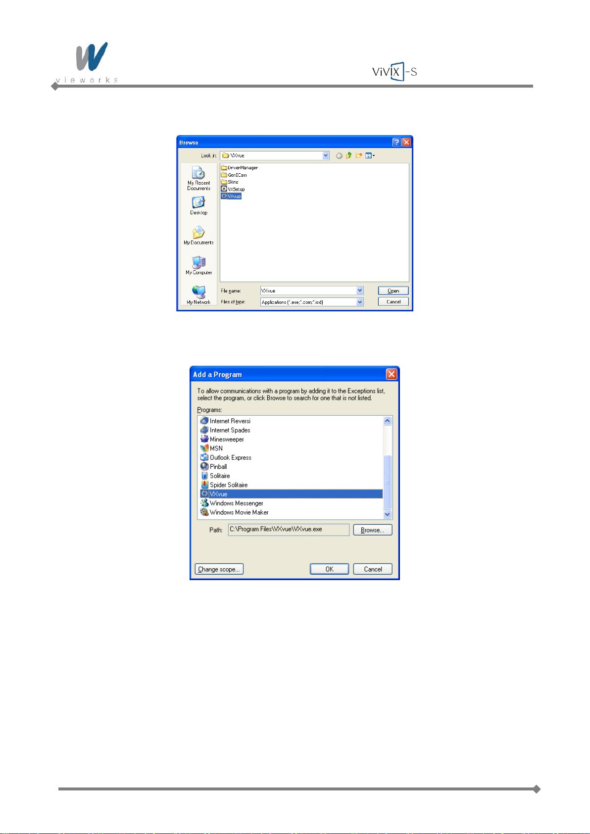
3 Click the Browse button and locate C:\Program files\VXvue\VXvue.
Page 72 of 124 RA14-11A-022
Page 73
Wireless Service Manual
4 Click the Open button.
5 Select the VXvue and then click the OK button.
Page 73 of 124 RA14-11A-022
Page 74
Wireless Service Manual
6 Check the VXvue to select and then click the OK button.
Page 74 of 124 RA14-11A-022
Page 75
Wireless Service Manual
4.2.6 Allowing VXvue to communicate through Windows Firewall on
Windows 7
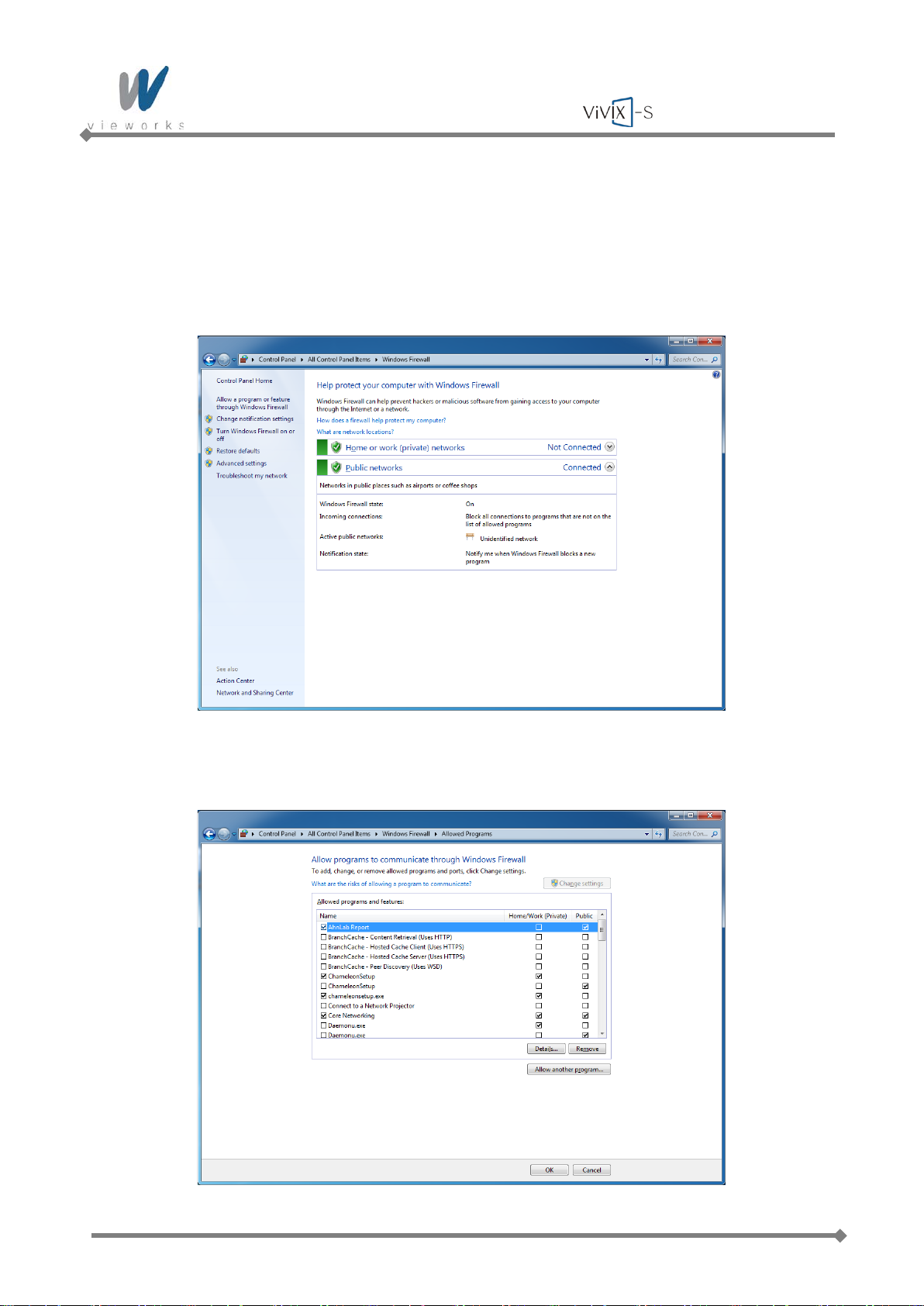
1 Click Start > Control Panel > Windows Firewall.
2 Click Allow a program or feature through Windows Firewall.
3 Click the Change settings button if it is enabled and then click the Allow another program button.
Page 75 of 124 RA14-11A-022
Page 76
Wireless Service Manual
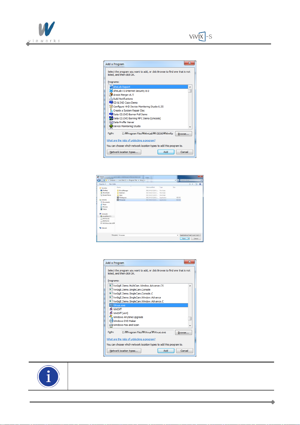
4 Click the Browse button and locate C:\Program files\VXvue\VXvue.exe.
5 Click the Open button.
6 Select the VXvue and then click the Add button.
Add VXSetup (located in C:\Program files\VXvue\VXSetup.exe) in the same manner as
described above.
Page 76 of 124 RA14-11A-022
Page 77
Wireless Service Manual
5. Prerequisite for Operation
5.1 Preparing the SCU
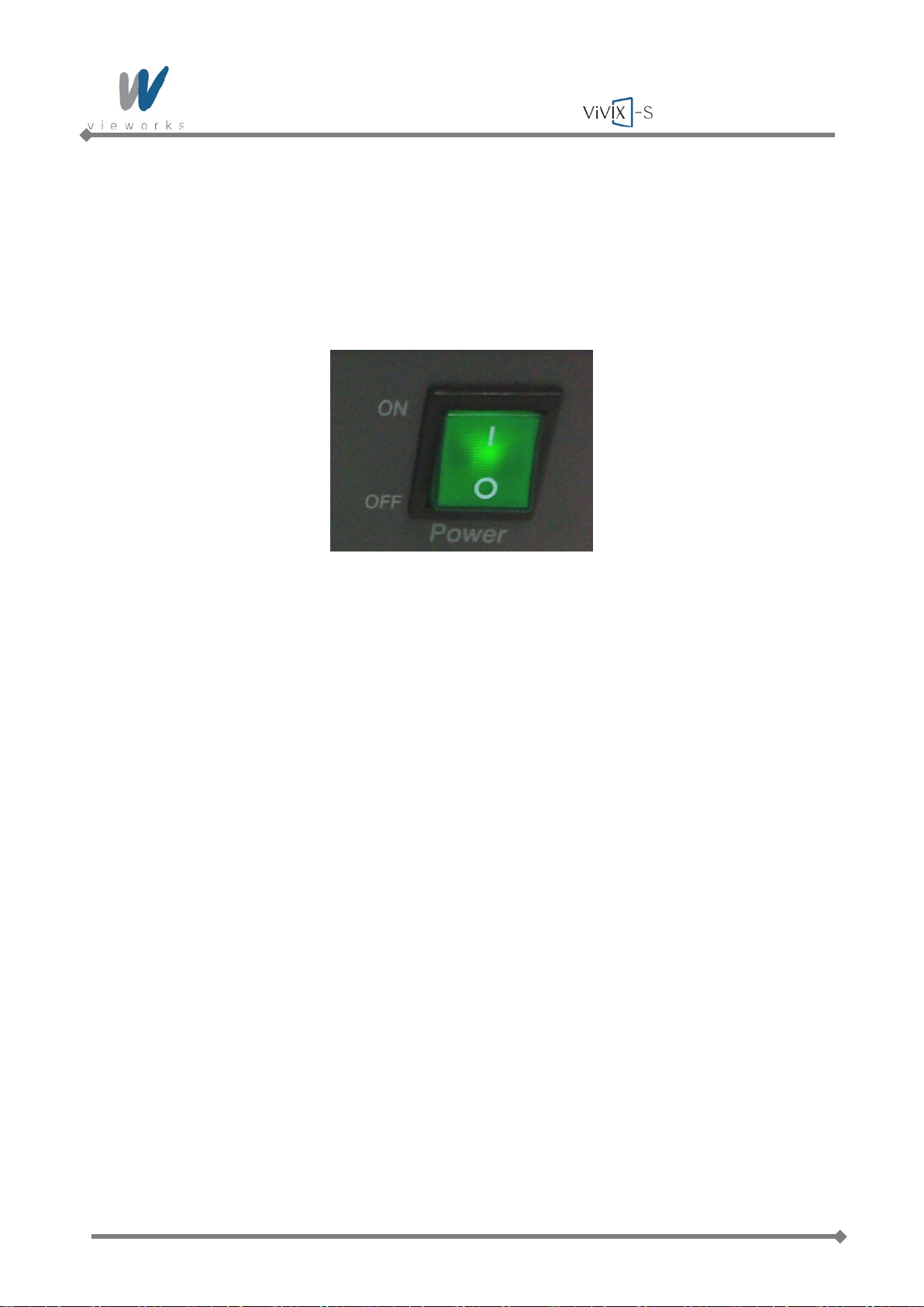
1 Turn on the System Control Unit (SCU).
2 Make sure the LED lamp (power and status) is lit green. It means SCU is ready to work normally.
3 Press and hold the power button of the detector for 3 seconds.
4 The detector Power LED is lit green and Active LED is lit orange simultaneously when the detector is
ready to operate.
5 Blinking green status LED indicates the startup process is in progress. Then status LED turns blue
indicating Wi-Fi network is connected.
Page 77 of 124 RA14-11A-022
Page 78
Wireless Service Manual
5.2 Generator Configur ati on
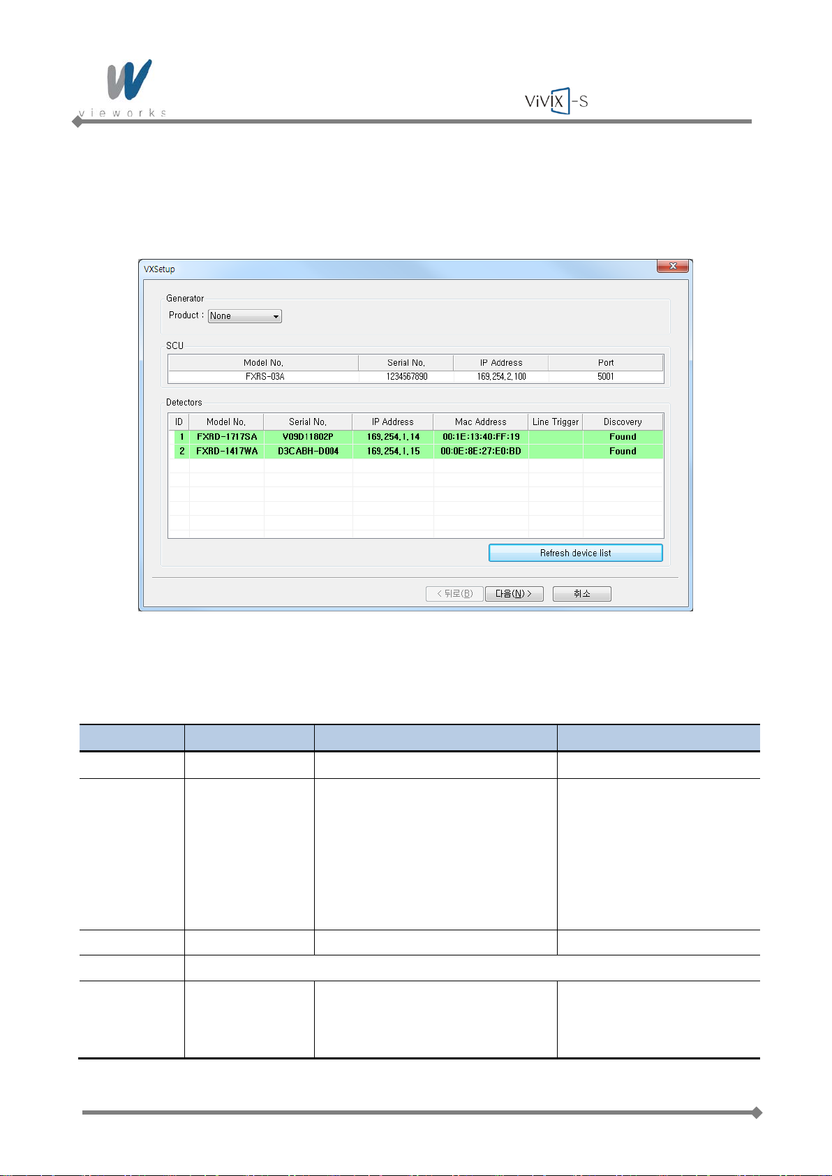
1 Run VXSetup.
2 Select a generator model from the dropdown list located beside Product in the Generator item. Input
proper values into Param1 and Param2 according to the generator model.
Generator Communication Settings Remarks
None No console
LISTEM Serial Param 1: Port
Param 2: ’true’ - Use AEC
‘false’ - No AEC
115200 bps / data 8 / stop 1 /
none / none
GXR UDP packet UDP 5001 Port
POSKOM Will be supported soon.
DK (Accuray) Serial Port COM 1
OCX Control
19200 bps / data 8 / stop 1 /
none / none
Page 78 of 124 RA14-11A-022
Page 79
Wireless Service Manual
Generator Communication Settings Remarks
CPI Serial Port COM 1
19200 bps / data 8 / stop 2 /
none / none
EMD Serial Port COM 3
Set WorkStation 2, 3
19200 bps / data 8 / stop 1 /
none / none
SEDECAL Shared memory Window title: ‘window title’ For Human in DRApp.ini
[SETTINGS]
DRAppName = window title
For Vet in AppName.ini
[CONFIG]
APPNAME= windo w tit le
5.3 Detector Configuration
In this phase, defect pixels are corrected and gained pixels are calibrated using installed x-ray generator and
x-ray tube. The detector needs to warm up at least 30 minutes before performing the calibration.
The calibration should be performed on the following cases.
Detector installation
X-ray generator replacement
X-ray tube replacement
Exposure section Value change
Gain Type change
Page 79 of 124 RA14-11A-022
Page 80
Wireless Service Manual
5.3.1 Detector Setting
1 Run VXSetup.
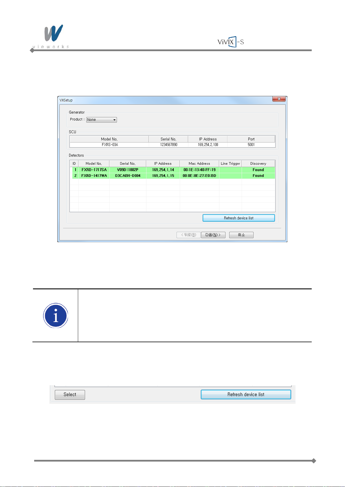
2 The connected detectors will be displayed under Detectors. If all the detectors are not displayed, click
the Refresh device list button to refresh the list.
Color used in indicating status
Green background: Connected normally and selected detectors
White background, black texts: Connected but not selected detectors
White background, gray texts: Recorded in the used history but not connected
detectors
3 To register connected detector to the system, double click the detector or select the detector and then
click the Select button activated on the bottom left.
Page 80 of 124 RA14-11A-022
Page 81
Wireless Service Manual
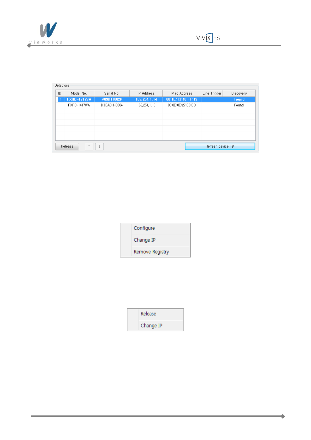
4 To deselect the registered detector, double click the detector or select the detector and then click the
Release button activated on the bottom left.
5 To sort the registered detectors, select the detector and then click the arrow button activated on the
bottom left.
6 To change the settings of connected detector or SCU, select the item and then click the right mouse
button.
SCU
- Configure: Changes the settings related to SCU described in chapter
5.3.2.1.
- Change IP: Changes the SCU IP.
- Remove Registry: Removes the data stored in the registry.
Detector
- Release: Deregisters the selected detector.
- Change IP: Changes the detector IP.
7 After completing configuration of detectors, click the Next button to synchronize the registered detectors
with SCU and proceed to next phase.
Page 81 of 124 RA14-11A-022
Page 82
Wireless Service Manual
5.3.2 Configuring Devices
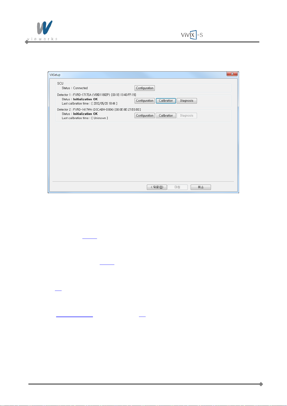
1 The list of connected SCU and registered detectors will be displayed.
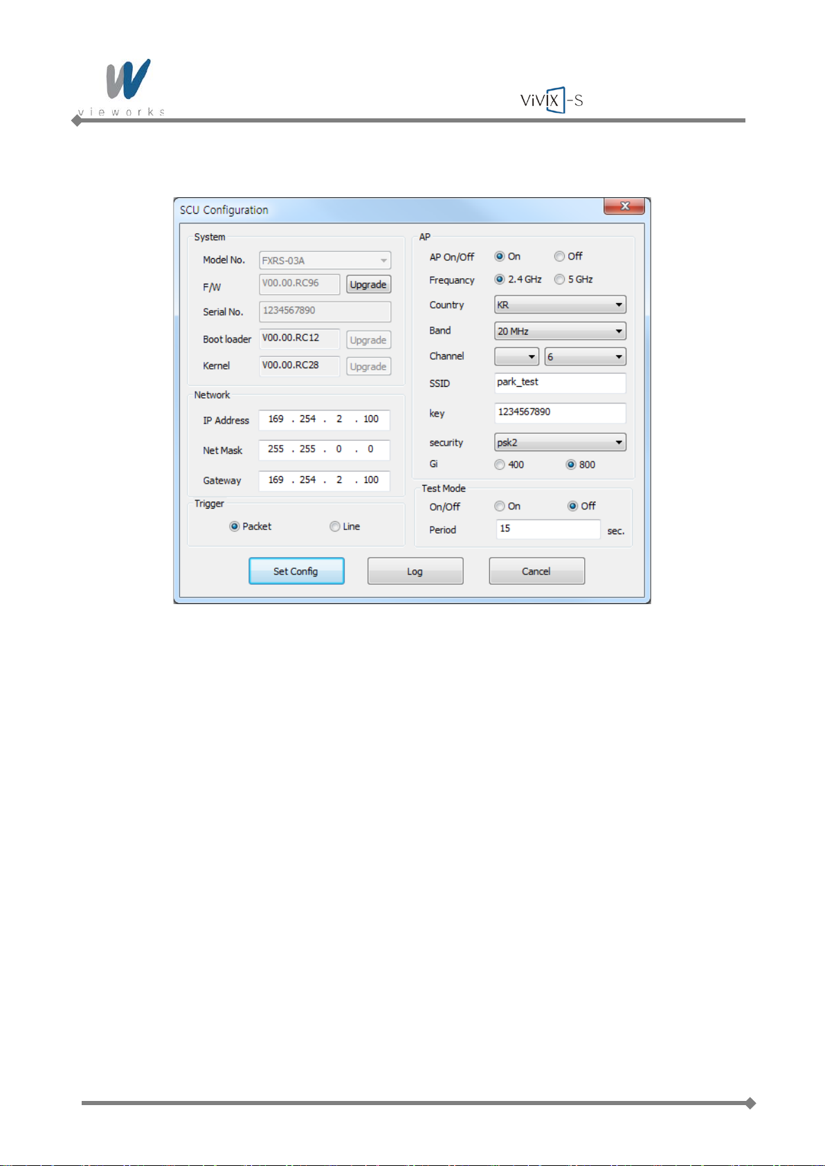
2 Click the Configuration button on the right side of SCU to display the SCU Configuration window
described in chapter
5.3.2.1.
3 Click the Configuration button on the right side of Detector to display the Detector Configuration
window described in chapter
5.3.2.2.
4 Click the Calibrate button on the right side of Detector to display the Calibration window described in
chapter
5.4.
5 After completing calibration of the detector, the Diagnose button will be activated. Click the button to
move to
Diagnosis Mode described in chapter 5.5.
Page 82 of 124 RA14-11A-022
Page 83
Wireless Service Manual
5.3.2.1 Configuring SCU
The SCU Configuration window allows you to configure the following items.
System
Model No.: Model number of SCU
F/W: Version of firmware
Serial No.: Serial number of SCU
Boot loader: Version of Boot loader
Kernel: Version of Kernel
Network
IP Address: IP address of SCU
Net Mask: Netmask of SCU
Gateway: Gateway address of SCU
Trigger
Packet: Use SW Trigger.
Line: Use HW Trigger.
Page 83 of 124 RA14-11A-022
Page 84

Wireless Service Manual
AP
AP On/Off: Configures whether to run SCU as AP mode.
Frequency: Frequency channel of wireless network
Country: Country code of wireless network
Band: Wireless network bandwidth
Channel: Wireless network channel
SSID: Wireless network ID
Key: Wireless network key value
Security: Authentication protocol for wireless network
Gi: Guard Interval of wireless network
Test Mode
On/Off: Configures w het her SCU transmits Trigger Packet within specified period.
Period: Configures the period of transmitting Trigger Packet in a second unit.
Page 84 of 124 RA14-11A-022
Page 85
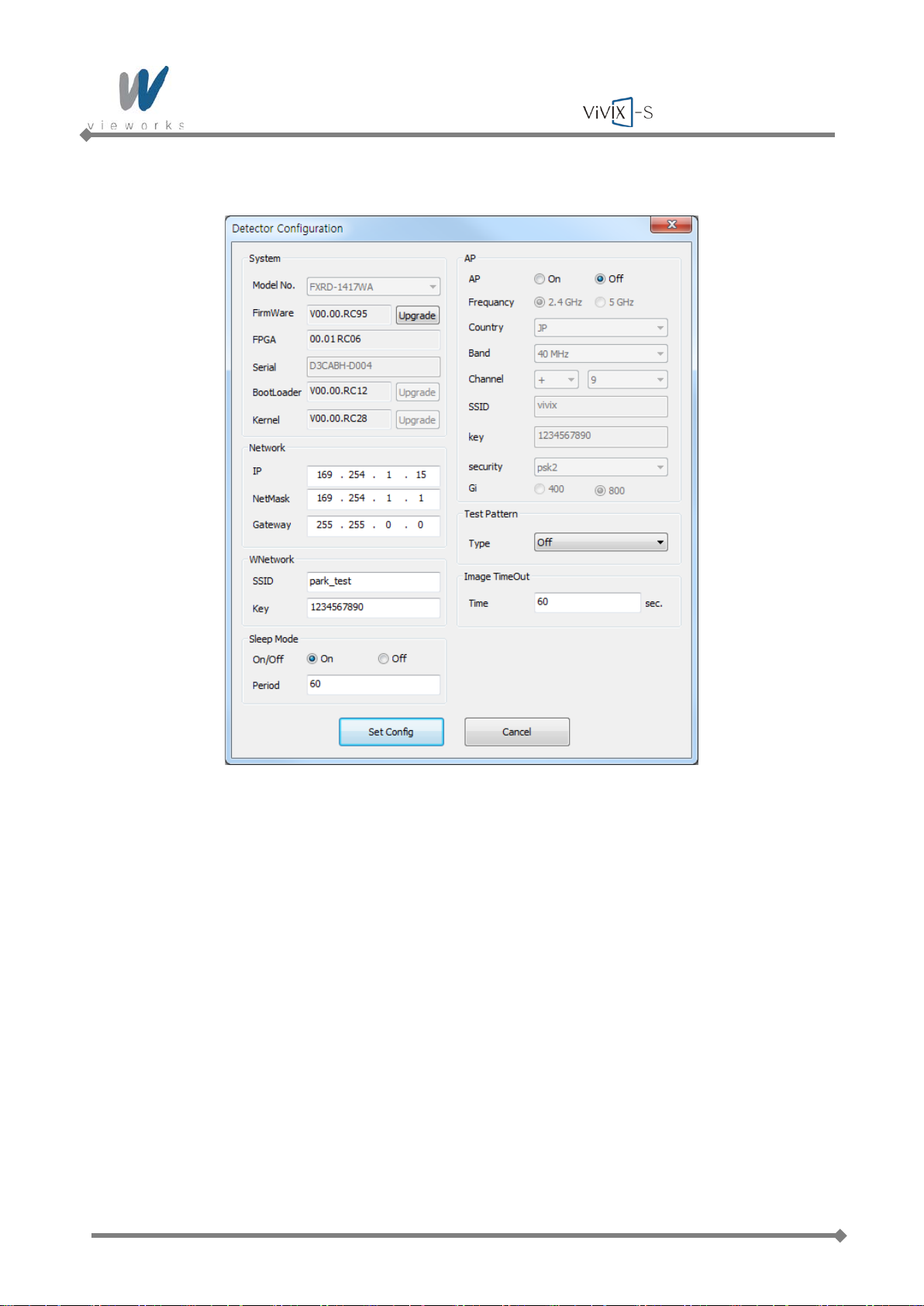
Wireless Service Manual
5.3.2.2 Configuring Detector
The Detector Configuration window allows you to configure the following item s .
System
Model No.: Name of device
FirmWare: Version of detector’s firmware
FPGA: Version of detector’s FPGA
Serial: Serial number of detector
BootLoader: Version of detector’s Boot loader
Kernel: Version of detector’s Kernel
Network
IP: Network IP address of detector
NetMask: Network Netmask of detector
Gateway: Network Gateway address of detector
Page 85 of 124 RA14-11A-022
Page 86

Wireless Service Manual
WNetwork
SSID: Wireless network ID of detector
Key: Wireless network key value of detector
Sle ep Mod e
On/Off: Configures whether the detector uses Sleep Mode.
Period: Configures the time of entering Sleep Mode.
AP
AP On/Off: Configures whether to run Detector as AP mode.
Frequency: Frequency channel of wireless network
Country: Country code of wireless network
Band: Wireless network bandwidth
Channel: Wireless network channel
SSID: Wireless network ID
Key: Wireless network key value
Security: Authentication protocol for wireless network
Gi: Guard Interval of wireless network
Test Pattern
Type: Type of detector’s test pattern image
Image TimeOut
Time Set timeout not to request transmission when acquired image is not transmitted
within specified time.
Page 86 of 124 RA14-11A-022
Page 87
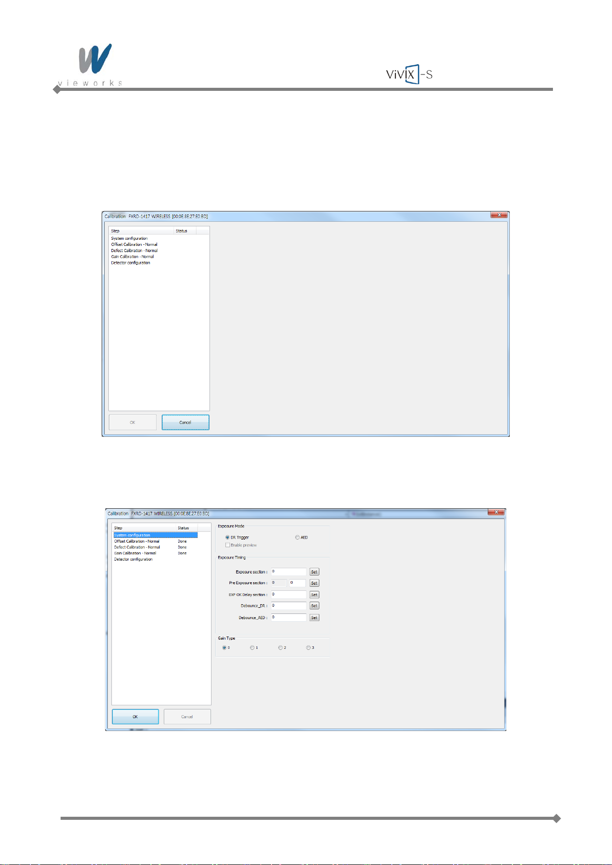
Wireless Service Manual
5.4 Detector Calibration
5.4.1 Configuring the Detector
1 Select System Configuration in the left Step item.
2 The information for the selected detector will be displayed.
Page 87 of 124 RA14-11A-022
Page 88
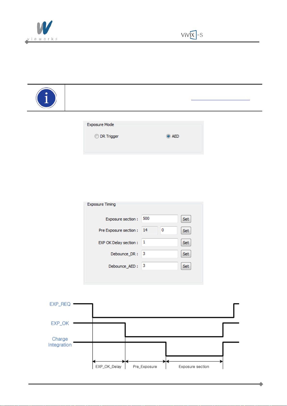
Wireless Service Manual
5.4.1.1 Setting Exposure Mode
User can set the detector to three different exposure modes according to the connection type to the X-ray
generator. Select the desired mode on System configuration.
For detailed information on X-ray exposure mode, refer to
2.6.1 X-ray Exposure Mode.
5.4.1.2 Timing Setting
To acquire correct images, exact timing setting must be made according to the characteristics of the X-ray
generator.
Page 88 of 124 RA14-11A-022
Page 89
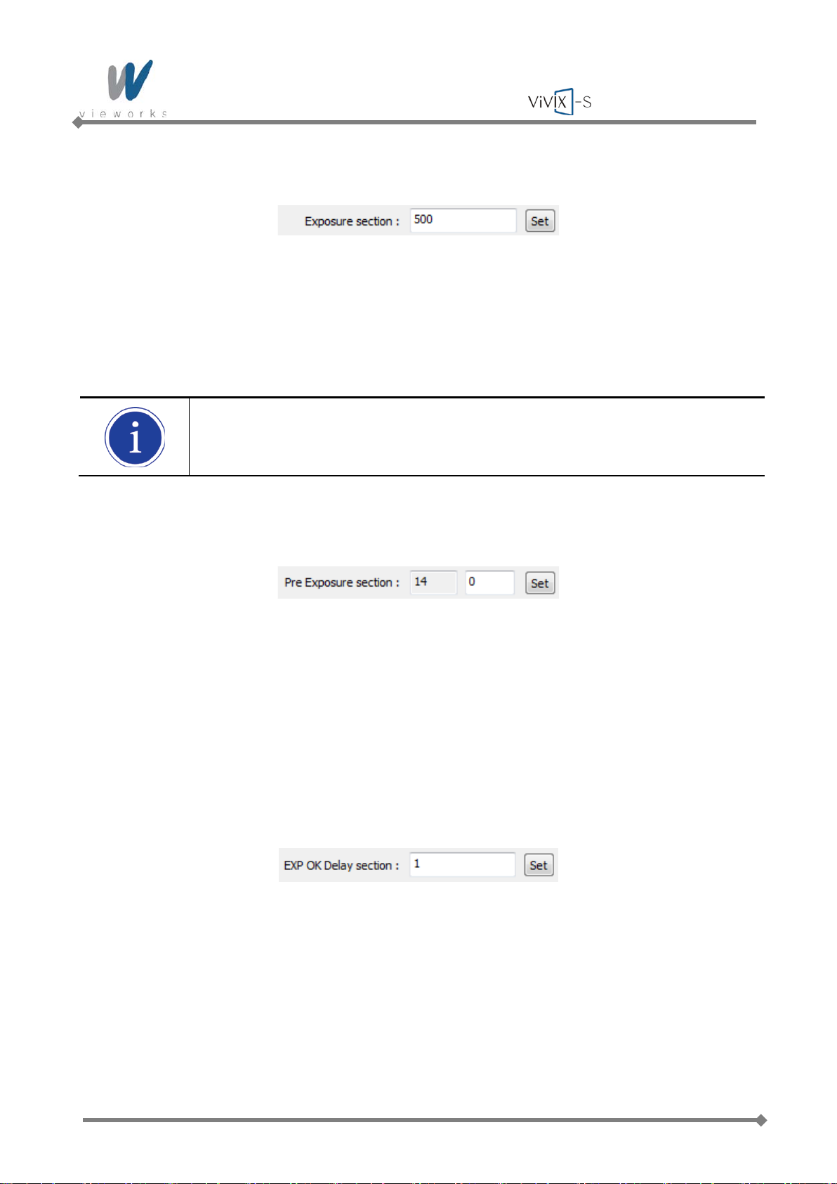
Wireless Service Manual
Exposure section
Exposure section indicates the period (unit: ㎳) that the detector converts X-rays to image signals. This
value needs to be set longer than the exposure time of X-ray generator to prevent X-rays loss while
converting X-rays to image signals. If you change the time settings, refresh the Post-offset data and generate
new GAIN data to acquire optimized images.
The recommended Exposure section value is 500 ㎳ (Standard).
Pre Exposure section
The Pre Exposure section is allowed to use when delay is occurred until the generator receives EXP-OK
signal from the detector and prepares X-ray generation. Pre Exposure section is set as 0 ㎳ normally,
however, it is recommend to set the actual delay time of generator’s X-ray generation with measurements to
achieve the best performance of the detector. The detector sends EXP_OK signal to the generator, then
transforms X-ray into image signal after the time set in the Pre Exposure section.
EXP OK Delay section
EXP OK Delay section is delay time from when the detector detects exposure request signal (EXP_REQ)
from the X-ray generator to when the detector sends exposure respond signal (EXP_OK) to the X-ray
generator. Some X-ray generators need some time to prepare detecting EXP_OK signal after sending
EXP_REQ signal. This value is determined according to the specifications of X-ray gener at or. The default
value is 1 ㎳.
Page 89 of 124 RA14-11A-022
Page 90
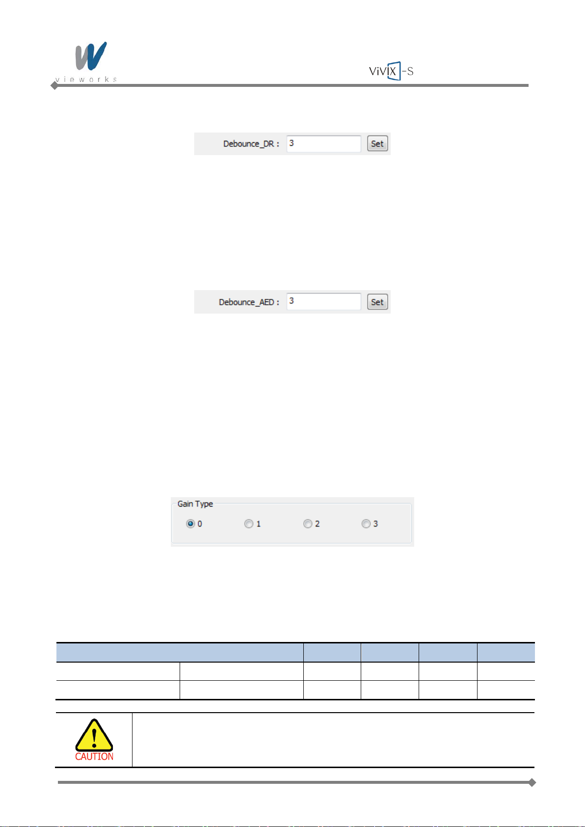
Wireless Service Manual
Debounce_DR
Debounce_DR is used to remove unwanted trigger signal occurred due to external noise when DR Trigger is
set as Exposure Mode. It is recommended to use the Debounce_DR setting value as default 3 ㎳. We
recommend setting the minimum exposure time of X-ray generator to more than 3 ㎳. If the value is set to
less than 3 ㎳, the detector may not acquire images.
Debounce_AED
Debounce_AED is used to prevent unwanted imaging occurred due to external noise when AED is set as
Exposure Mode. It is recommended to use the default values set by manufacturer. We recommend setting
the minimum exposure time of X-ray generator to more than the value set in the Debounce_AED. If the value
is set to less than the settings in the Debounce_AED, the detector may not acquire images.
If unwanted images are acquired without X-ray exposure while operating the equipment, set Debounce_AED
with 1 ㎳ increments. However, make sure not to exceed 5 ㎳ since an image degradation may appear in
the image if Debounce AED exceeds 5 ㎳.
5.4.1.3 Gain Type Setting
To acquire X-ray image with proper brightness, adjust the Gain Type setting. You can select the Gain Type to
adjust the sensitivity of the detector, then you can acquire X-ray images with desired brightness according to
the specifications of X-ray generator or the type of objects. The default gain type is 1.
The following table describes each Gain Type of the sensitivity ratio.
Gain Type 0 1 2 3
Gadox Detector Sensitivity ratio 0.86
CsI Detector Sensitivity ratio 0.62
1
1
1.2 1.5
1.14 1.33
The owner is responsible for ensuring that the Gain Pixel Correction is performed after
adjusting the Gain Type.
Page 90 of 124 RA14-11A-022
Page 91
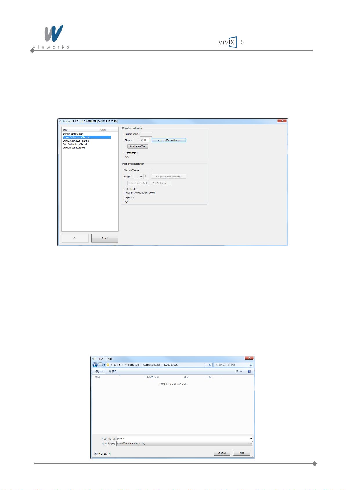
Wireless Service Manual
5.4.2 Offset Calibration
5.4.2.1 Pre-offset Calibratio n
1 Select Dark acquisitio n –Normal and click the Load pre-offset button to apply pre-offset data which is
provided with the flat panel detector.
2 When you create new pre-offset data, input the number of images to be acquired to Stage in the Pre-
offset calibration item and then click the Run pre-offset calibration button.
3 Acquiring image process will be proceeded automatically, then the average value of acquired images
will be displayed in Current Value and the current status will be displayed in Stage.
4 After acquiring images, a window for saving created pre-offset data appears, then specify a directory to
save the data.
Page 91 of 124 RA14-11A-022
Page 92
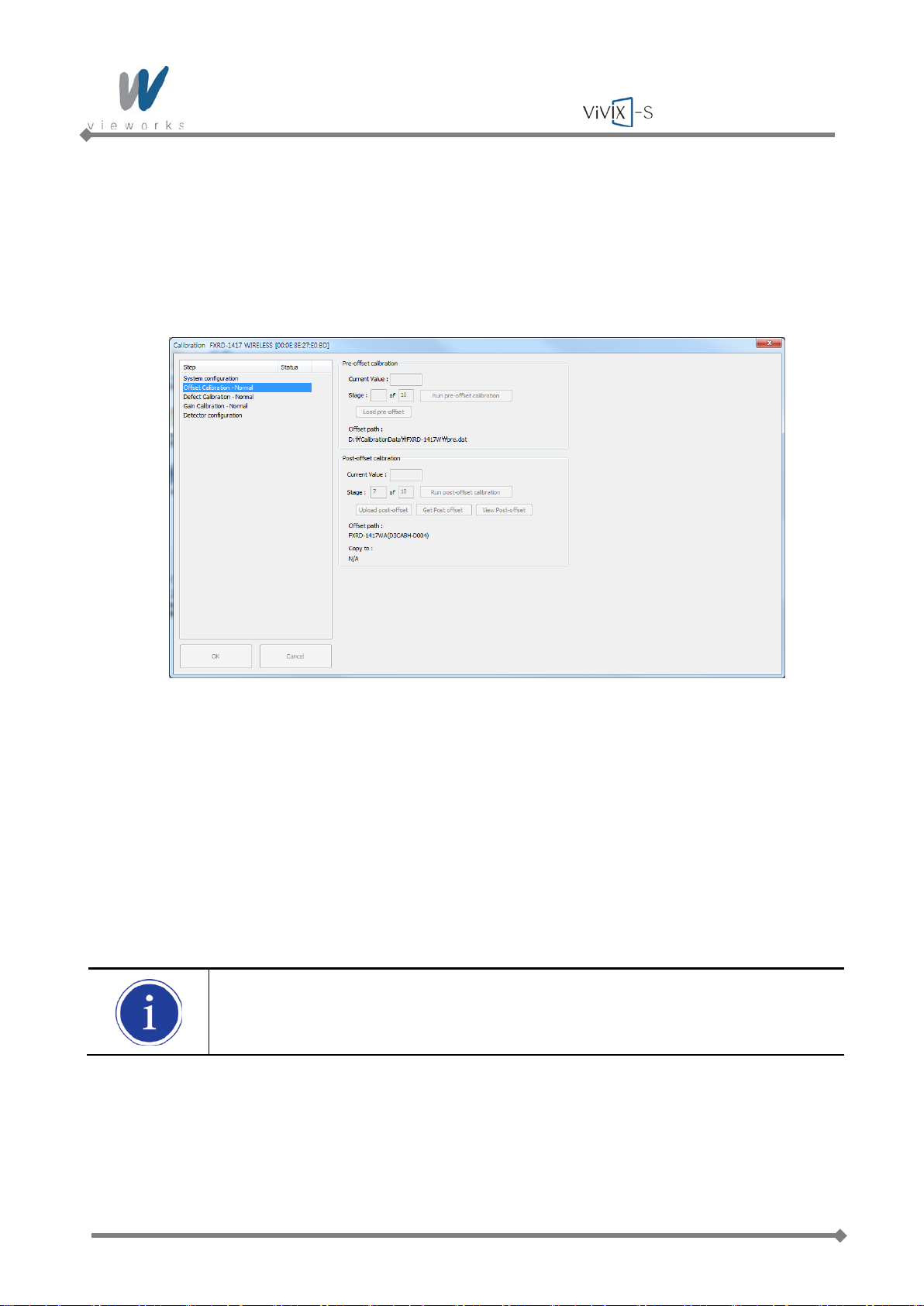
Wireless Service Manual
5.4.2.2 Post-offset Calibrati on
1 Click the Get Post offset button to locally save the offset file that is backed up on the detector.
2 When you create new post-offset data, input the number of images to be acquired to Stage in the Post-
offset calibration and click the Run post-offset calibration button.
3 Acquiring image process will be proceeded automatically, then the average value of acquired images
will be displayed in Current Value and the current status will be displayed in Stage.
4 After acquiring images, a window for saving created post-offset data appears, then specify a directory to
save the data.
5 To save the previously created post-offset file to the detector, click the Upload post offset button and
then select the file to upload.
The offset data that is already uploaded to the detector will be used for acquiring images
with wireless detector instead of the data stored in the local.
Page 92 of 124 RA14-11A-022
Page 93

Wireless Service Manual
5.4.3 Defect Correction
5.4.3.1 Load defect map
1 Select Defect detection – Normal in the left Step item.
2 Click the Load defect map button to apply the defect data which is provided with the flat panel detector.
Page 93 of 124 RA14-11A-022
Page 94
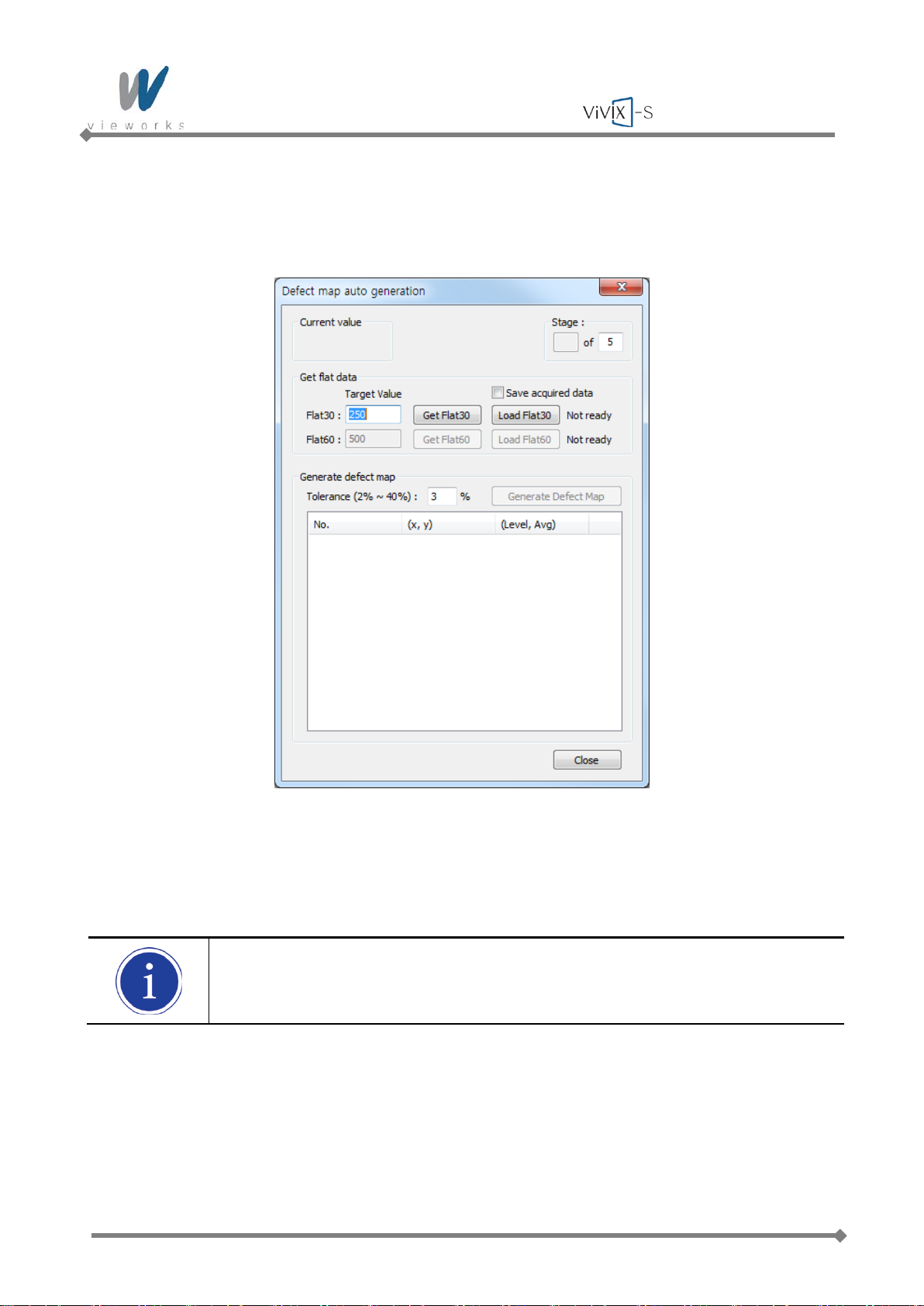
Wireless Service Manual
5.4.3.2 Auto defect detection
1 To create new defect map, apply the Defect data which is provided with the flat panel detector and then
click the Auto defect detection button.
2 Acquire X-ra y images and adjust the doses of radiation to match the Current value to the Target Value of
Flat30. When the Current value reaches within 10% of Target Value, keep the doses of radiation at that
point.
For Flat30 and Flat60 the recommended Target Values are respectively 250 and 500.
3 To save the collected image data, check the Save acquired data checkbox. Once the images of Flat30
and Flat 60 are acquired, it is allowed to save as a file.
4 Click the Get Flat30 button to acquire as many images as the number set at the top of the Stage. Or,
load the Flat30 image which is previously saved by clicking the Load Flat30 button.
Page 94 of 124 RA14-11A-022
Page 95
Wireless Service Manual
5 Acquire X-ray images and adjust the doses of radiation to match the Current Value to the Target Value
of Flat60. When the Current value reaches within 10% of Target Value, keep the doses of radiation at
that point.
6 Click the Get Flat60 button and acquire as many images as the number set at the top of the Stage. Or,
load the Flat60 image which is previously saved by clicking the Load Flat60 button.
7 Enter the detection range of Defect data into the Tolerance field based on the acquired images.
The recommended Tolerance value is 3%.
8 Click the Generate Defect Map button, create the new Defect Map Data file, and then save it.
No need to click the Load defect map button since the Defect Map file is automatically
created and loaded.
Page 95 of 124 RA14-11A-022
Page 96
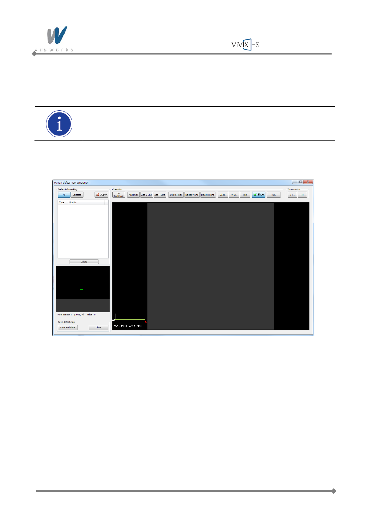
Wireless Service Manual
5.4.3.3 Manual defect detection
1 To create the new defect map manually, click the Manual defect detection button after applying Defect
data provided accordingly.
To use the Manual defect detection feature, the previously acquired dark image is needed.
The dark image can be acquired in the Diagn osis Mod e.
2 Select the original image file of the detector to find the defect data.
Page 96 of 124 RA14-11A-022
Page 97
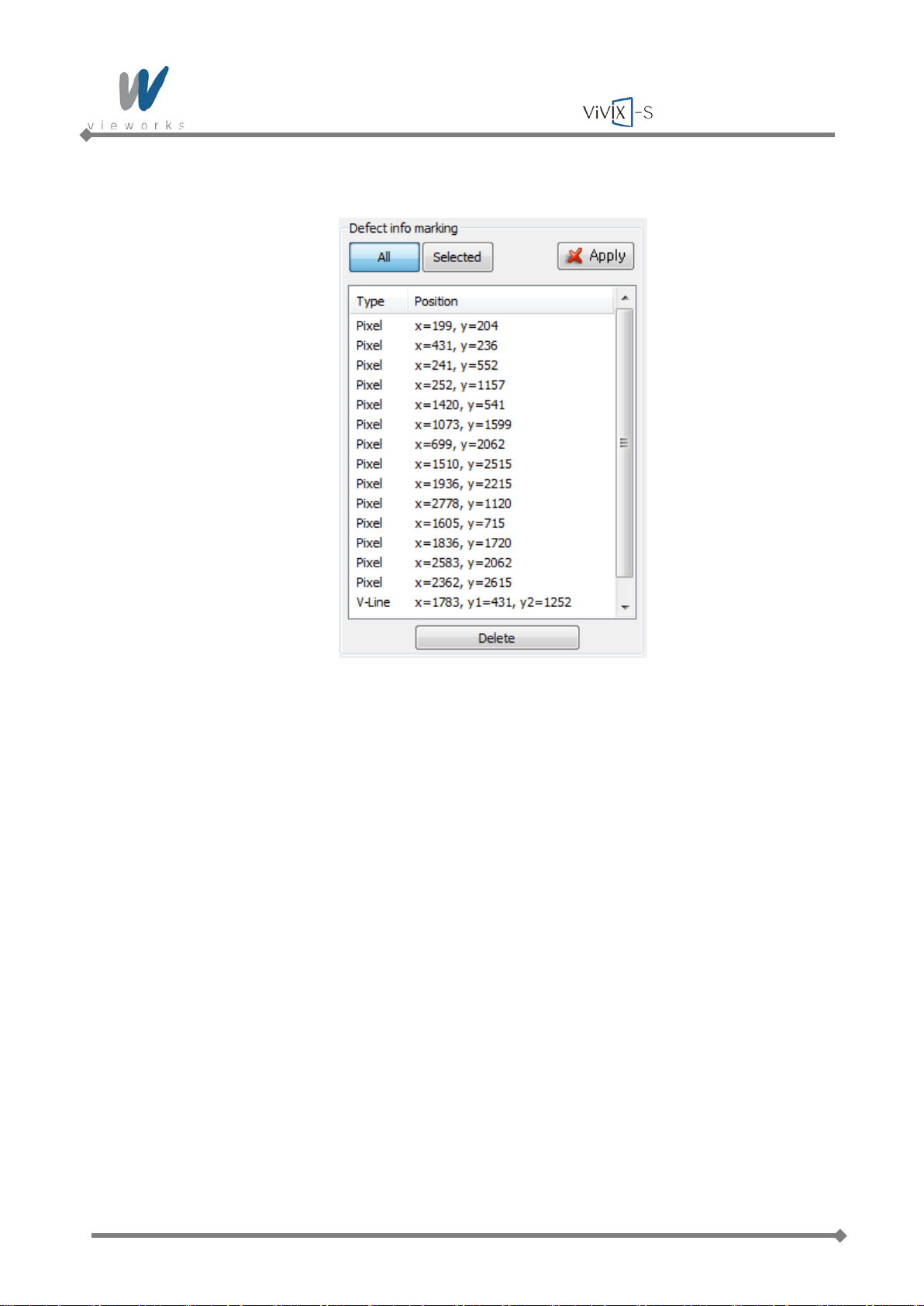
Wireless Service Manual
Defect info marking
Apply: Apply Defect information of selected items from the list to image.
All: Apply all items from the list.
Selected: Apply the only selected items from the list.
Delete: Delete the selected items from the list.
Page 97 of 124 RA14-11A-022
Page 98
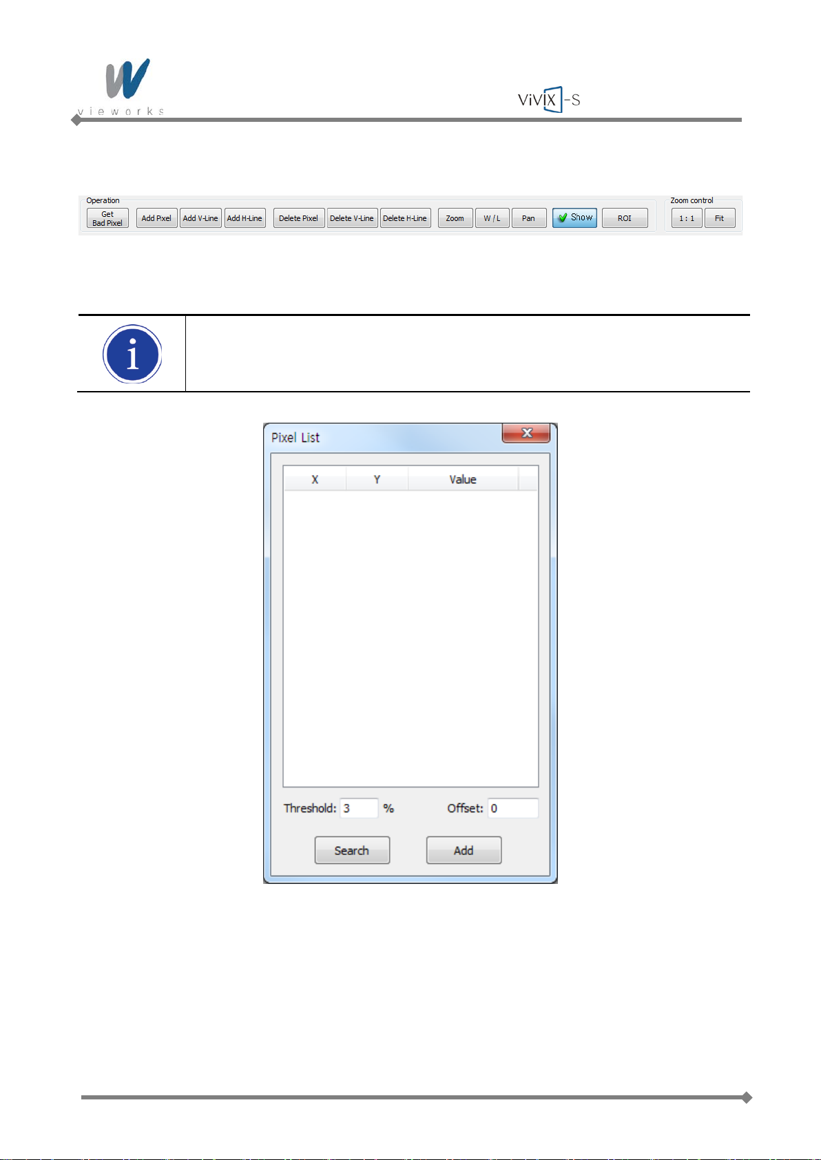
Wireless Service Manual
Operation / Zoom control
Get Bad Pixel: Automatically detect the defect pixel from the currently displayed image.
When you select the Get Bad Pixel feature, all items of the Defect info marking list are
automatically applied to the image.
1 Enter the value of threshold and offset to detect the defect pixel.
2 Click the Search button to search the automatically detected list.
Page 98 of 124 RA14-11A-022
Page 99

Wireless Service Manual
3 Select an item to add to the Defect list, and then click the Add button.
Add Pixel: Add one pixel unit of defect pixel.
Add V-Line: Add line type of defect pixels vertically.
Add H-Line: Add line type of defect pixels horizontally.
Delete Pix el: Delete one pixel unit of defect pixel.
Delete V-Line: Delete line type of defect pixels vertically.
Delete H-Line: Delete line type of defect pixels horizontally.
Zoom: Zoom in or out the image.
W/L: Adjust the window level of the image.
Pan: Move the image.
Show: Determine whether to display the selected defect pixel on the image.
ROI: Automatically adjust the window level based on the Min. and Max. value of the
selected area.
1:1: Display the image at one to one ratio.
Fit: Display the image to fit into the screen.
4 Once it is finished to display the defect pixels in the image, save the newly created defect map file and
complete the process by clicking the Save and close button. To cancel it, click the Close button.
Page 99 of 124 RA14-11A-022
Page 100
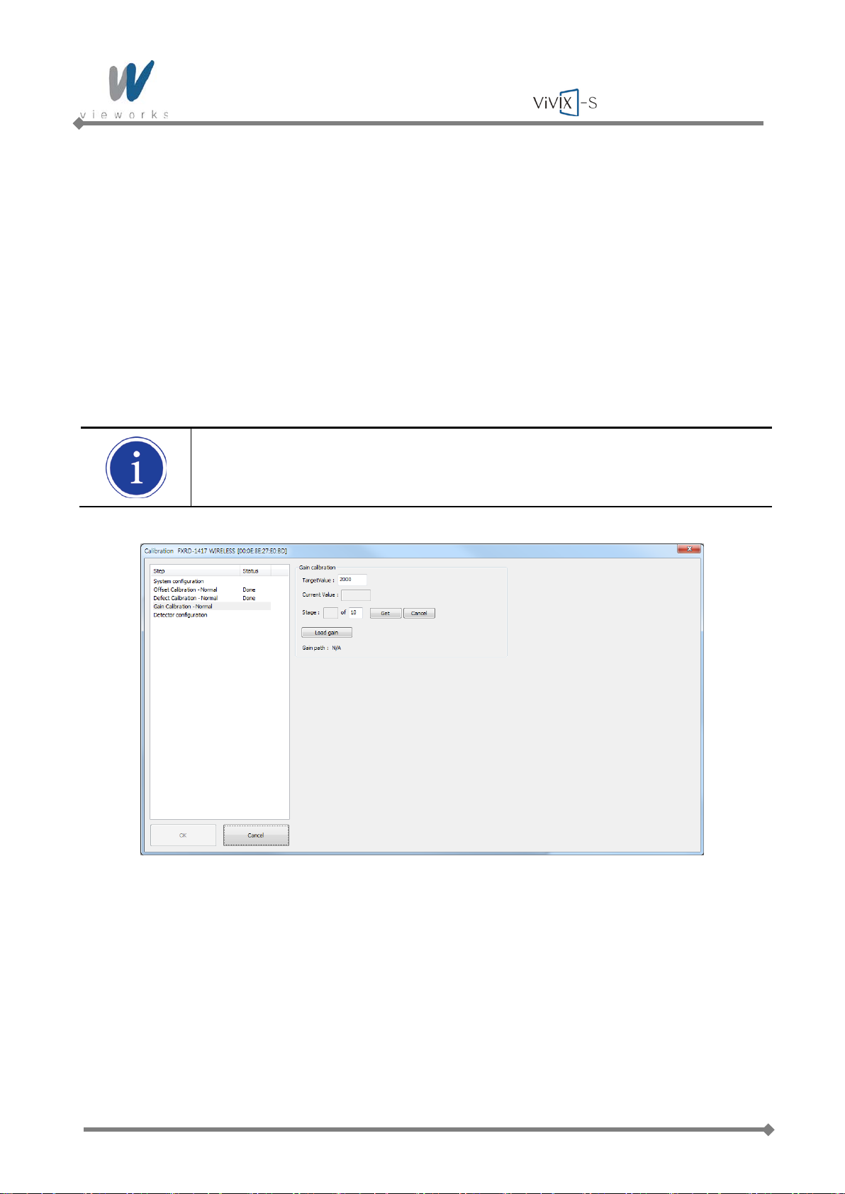
Wireless Service Manual
5.4.4 Gain Pixel Correction
Before performing Gain Pixel Correction, consider followings:
Recommended SID is 150 ㎝ (distance between X-ray tube and Detector).
Open the collimator of X-ray tube completely.
Align the center of the detector with the center of collimator.
Keep everything away from the detector surface.
1 Select Gain acquisition – Normal in the left Step item. Expose X-rays and adjust dose of X-rays so
that Current Value reaches TargetValue. Keep the quantity of X-rays when Current Value remains within
10% difference of TargetValue.
Recommended TargetValue is 2000.
2 Click the Get button and expose X-rays ten times.
3 Save the Gain data to the desired folder.
4 Once all the procedures are completed, the OK button will be activated. Click the OK button to close the
dialog box.
Page 100 of 124 RA14-11A-022
 Loading...