

Page 1
Technical Data Manual
VITOTRONIC 300
Weather-responsive indoor/outdoor, digital boiler control
for heating systems with one or more heating circuits
Vitotronic 300
Model KW3, Part No. Z001 231
For operation with modulating boiler water temperatures
and single-stage, two-stage or modulating burners
For heating systems with one heating circuit without mixing
valve and up to two heating circuits with mixing valves
With DHW tank temperature sensor and integrated
diagnostic system
Operating module with clear text LCD display
Remote control interface with or without room temperature
sensing
Viessmann quick-connect plug-in system
5265 533 v1.4 09/2011
Certified as a component part
of Viessmann boilers only
Page 2
Product Information/Standard Equipment/
Application
Product Information
The benefits at a glance:
H Easy and uniform operation:
-- Different programming levels for
system user and heating contractor
-- Large, clear text LCD display format
facilitates legibility of all data
-- Illuminated operating mode and
heating circuit keys
-- Easy-to-program switching times
-- Digital tracking of day and week.
Programmed times for domestic hot
water production and recirculation
pump is adjusted automatically when
heating program is altered.
-- Plug & Work quick-connect system for
automatic sensor/system recognition
and adaptation
-- Automatic resetting to daylight
savings time
-- Service interval display for
demand-related maintenance
-- Fuel consumption display
H Program selection for controlled drying
of concrete floor in radiant floor heating
application
H Short installation time, start-up and
maintenance due to Rast-5 connector
system, plug-in function modules and
integrated diagnostic system
Vitotronic 300, Model KW3
OTS
STS STS
H Weather-responsive indoor/outdoor,
digital boiler and heating system
control:
-- for heating systems with one boiler
-- for heating systems with one
direct-connected heating circuit and
up to two mixing valve circuits
-- for single-stage, two-stage and
modulating burners
-- with DHW tank temperature sensor
-- with digital tracking of day and week
-- with separate switching times for
space heating, domestic hot water
heating and recirculation pump
-- with integrated diagnostic system
Standard Equipment
Vitotronic 300, Model KW3
(Part No. Z001 231)
with
H operating module with clear text LCD
display
H outdoor temperature sensor
H boiler water temperature sensor
H DHW tank temperature sensor
H Power/Pump Module
For a heating circuit with a mixing valve,
a mixing valve actuator accessory kit is
required. Due to the low return water
temperature of condensing boilers only
3-way mixing valves should be installed.
For non-condensing boilers, such as
Vitogas 100, Vitorond 200 and Vitola
200, a 4-way mixing valve may be used.
The circulation pump with a flow check
valve for DHW tank temperature control
must be ordered separately.
Heating system with underfloor heating
The underfloor heating circuit requires an
accessory kit for operation with a mixing
valve.
A temperature control with high limit
must be installed into the flow of the
radiant floor heating application.
The underfloor heating circuit must not
be controlled by a remote control with
room temperature sensor.
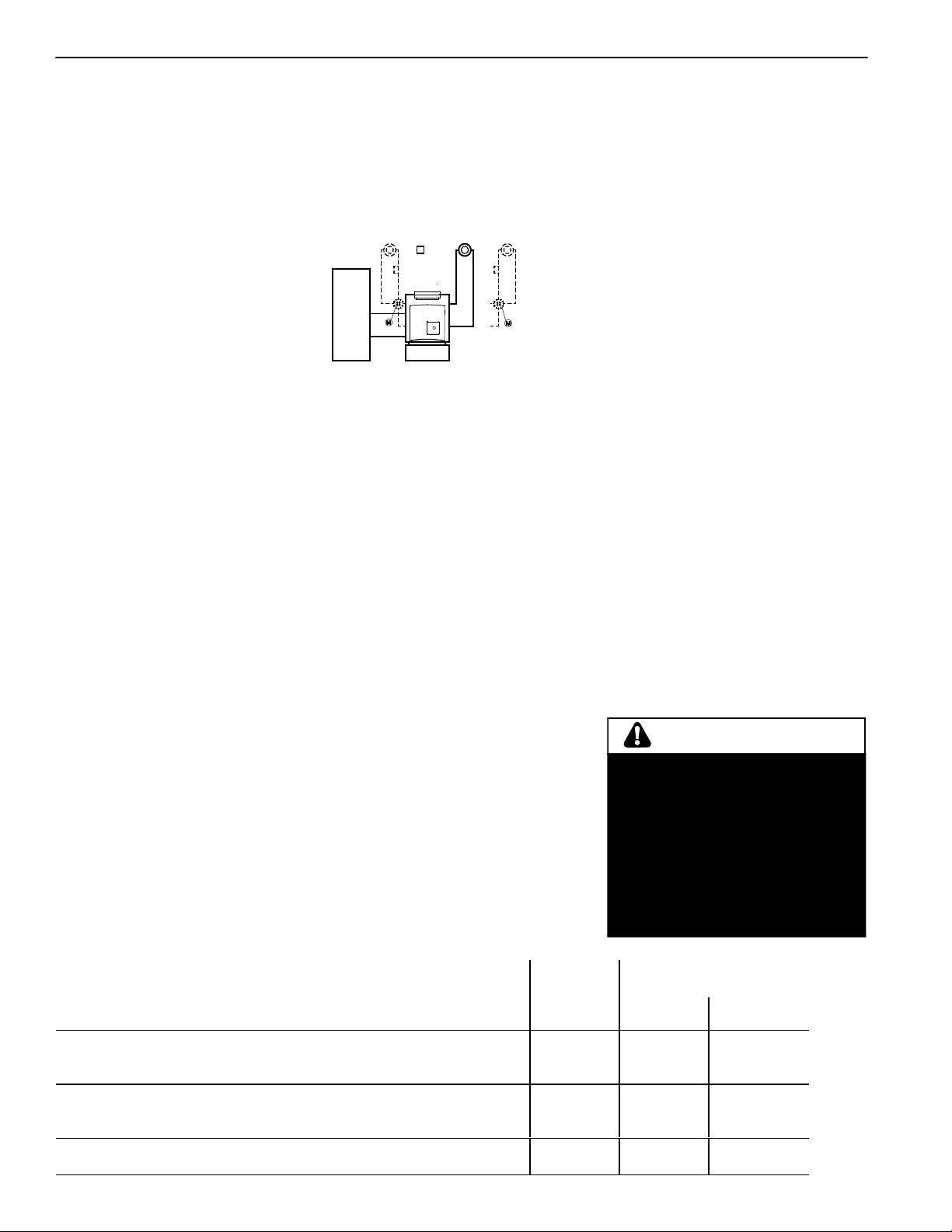
Application
In conjunction with the following Viessmann boilers
Boiler Model and Series
Oil-/gas-fired hot water
heating boiler with power
burner
Atmospheric
gas-/propane-fired hot
water heating boiler
Atmospheric gas-fired
hot water heating boiler
Vitola 200
Vitogas 050, RS Series
Vitogas 100, GS1 up to 240 MBH / 70 kW
Vitogas 100, GS10 up to 380 MBH / 111 kW
Fuel
Oil/Gas
Gas
Gas
Gas
WARNING
When extending wire, there is the
possibility of exposure to
electromagnetic interference.
Avoid running wires beside or near
high voltage 120/240 VAC
conductors. If proximity to high
voltage conductors cannot be
avoided, use stranded, twisted pair
or shield design wire. Ensure that
only one end of the shielding is
grounded.
Minimum boiler water
temperature
without low
limit
x
with low limit
(average temp.)
120 ºF / 49 ºC
104 ºF / 40 ºC
120 ºF / 49 ºC
5265 533 v1.4
2
Page 3

Structure and Operation
Structure and Operation
Modular structure
The complete control consists of a
control base, control unit (electronic
operating modules), and a Power/Pump
Module.
The control unit comprises:
Power on/off switch, an electronic high
limit, a temperature gage and a low
temperature control
-- adjustable high limit
-- fixed high limit
TUV test switch, override switch,
buttons for:
-- holiday program
-- party and economy modes
-- reduced operating mode temperatures
-- domestic hot water temperature
-- programming of heating curves for
boiler water temperature, mixing valve
circuit temperature
-- heating circuit selection,
a selector knob for normal operating
temperatures and a digital timer.
Heat-demand-controlled circuit pump and
burner activation, adjustment option for
variable temperature limit, pump cycling,
integrated diagnostic system and flue gas
monitoring in connection with the flue
gas temperature sensor (optional) and
maintenance display.
Boiler-specific functions
The Vitotronic control modulates the
boiler water temperature.
It gradually regulates the boiler water
temperature (= the supply water
temperature of the direct-connected
heating circuit) as well as the supply
water temperature of a mixing valve
circuit. The control contains an adaptive
tank temperature control logic with
priority switching (heat pump off, mixing
valve closed).
An additional function for domestic hot
water heating (short-term heating to an
increased temperature) can be selected.
5265 533 v1.4
The Vitotronic 300 is an ideal control
option for your heating system with
mixing valve circuit. It is the perfect
solution for your underfloor heating
circuit with supply and return water
temperature sensor or for controlled
drying of a concrete floor.
Control characteristics
-- Boiler circuit control unit (high
temperature)
-- Heating circuit control with mixing
valve
-- Dead band: ±1.80 ºF / 1 ºC
-- Adjustable high limit factory default
setting: 167 ºF / 75 ºC
adjustable to
205 ºF / 96 ºC
-- Fixed high limit:
230 ºF / 110 ºC
adjustable to
212 ºF / 100 ºC
-- Adjustment range of heating curve:
Slope: 0.2 to 3.5
Shift: – 23 ºF to +72 ºF
– 13 ºC to +40 ºC
High limit: 68 to 266 ºF
20 to 130 ºC
Low limit: 34 to 261 ºF
1 to 127 ºC
Differential temperature for heating
circuit with mixing valve:
0 to 72 ºF
0 to 40 ºC
-- Adjustment range for domestic hot
water setpoint temperature:
50 to 140 ºF
10 to 60 ºC,
adjustable to
50 to 203 ºF
10 to 95 ºC
Technical data
Rated voltage: 120 VAC
Rated frequency: 60 Hz
Rated current: 6 A
Power consumption: 5 W
Maximum ambient
temperature
-- at operation: 32 to 104 ºF
0 to 40 ºC
(in rooms and
installation sites
with normal
ambient
conditions)
-- when storing or transporting:
–4 to +149 ºF
–20 to +65 ºC
Relay output rating in conjunction with a
Power/Pump Module:
-- Heating circuit
pump : 3 FLA / 120 VAC
-- Circulation pump
for DHW tank
heating
-- DHW recirculation
: 3 FLA / 120 VAC
pump : 3 FLA / 120 VAC
-- Compiled fault
indicator : 3 FLA / 120 VAC
-- Burner plug : 2 FLA / 120 VAC
Two-stage burner
*2
plug
-- Power supply to
: 0.5 FLA / 120 VAC
Power/Pump
Module: max. 12 A /
120 VAC
*1
Total 9 A / 120 VAC
*2
Available only with extension module
for two-stage burner (included in boiler
package).
Boiler coding card
For adapting the control to the heating
boiler and the respective heating system
characteristics (included in boiler
package).
Connections
-- Sensors, burner and Power/Pump
Module are connected to the back of
the control unit via system plugs.
-- Pumps and power supply are connected
to the Power/Pump Module via screw
terminals or system plugs.
-- Mixing valve pumps and mixing valve
supply sensors are connected to the
mixing valve controller. The mixing
valve controller receives power from a
separate power source and
communicates with the Vitotronic via
the 2-wire KM-BUS.
Operating unit
-- With digital timer
-- Clear text LCD display
-- Temperature and error message display
-- Coding via display of operating unit
-- All adjustments and basic coding
information in clear text
*1
*1
*1
*1
3
Page 4

Structure and Operation
Digital timer of operating unit
A digital timer with day and week
feature, calendar, automatic resetting to
daylight savings time and automatic
functions for domestic hot water heating
and recirculation pump.
Time, day and standard switching times
for space heating, domestic hot water
heating and the domestic hot water
recirculation pump are factory preset
(individually programmable), max. four
time switch intervals programmable per
day
Shortest interval: 10 minutes
Power reserve: 5 years
Adjusting the operating mode
All operating modes provide freeze-up
protection
*1
for the heating system.
With the program selector buttons the
following can be selected:
-- heating and domestic hot water
-- domestic hot water only
-- standby operation
*1
see “Freeze-up protection function”
below.
Freeze-up protection function
The freeze-up protection function is
-- activated when the outdoor
temperature drops to +34 ºF / 1ºC.
Freeze-up protection activates the
circulation pumps and keeps the boiler
water temperature at the reduced
operation setpoint level, at a minimum
temperature of approx. 68 ºF / 20 ºC
(for heating boilers with low limit the
respective temperature will be
maintained).
-- deactivated when the outdoor
temperature exceeds 37 ºF / 3 ºC.
When the freeze-up protection function
is deactivated, heating boiler and
circulation pumps are turned off.
Heating curve adjustment
The weather-responsive Vitotronic 300
regulates the boiler water temperature
(= supply temperature of the heating
circuit without a mixing valve) and the
supply temperature of the heating circuit
with mixing valves.
Boiler water temperature is maintained
from 0 to 72 ºF / 0 to 40 ºC above the
calculated supply temperature of either
mixing valve circuit (factory default
setting 5 ºF / 8 ºC).
The required boiler supply temperature
for a certain room temperature depends
on the heating system and the insulation
of the building in question. The
adjustment of each heating curve allows
for the boiler water temperature and the
supply water temperature of the mixing
valve circuits to adjust to these
conditions.
Heating curves:
Low temperature heating system,
e.g. radiant floor heating
Medium temperature heating system,
e.g. cast iron radiation, staple-up
radiant floor heating
High temperature heating system,
e.g. fintube radiation, fan coils
Boiler water temperature sensor
Cable length 5.2 ft./1.6 m,
ready to plug in.
Maximum ambient temperature
– at operation: 32 to 266 ºF
0 to 130 ºC
– when storing or transporting:
–4 to +158 ºF
–20 to +70 ºC
Outdoor temperature sensor
Installation site:
-- North or northwest side of building
-- 6.6 to 8.2 ft. / 2 to 2.5 m above
ground, for multi-storey buildings mount
sensor on upper half of second floor.
Connection:
-- 2-wire cable, cable length 115 ft. /
35 m with a wire size of min. AWG 16
copper.
-- the cable to the outdoor sensor must
not be laid near line voltage wiring
(120 / 240 V).
Maximum ambient temperature at
operation,
when storing or
transporting: – 40 to +158 ºF
– 40 to +70 ºC
Domestic hot water tank temperature
sensor
Summer economy mode
(Domestic hot water heating only,
program selector switch ” ”)
The burner only activates if domestic hot
water needs to be produced (as required
by DHW setpoint).
4
The maximum boiler water temperature is
restricted by both the adjustable high
limit and the electronic maximum
temperature limit.
The supply water temperature cannot
exceed the boiler water temperature.
Cable length 19 ft. / 5.8 m,
ready to plug in.
Maximum ambient
temperature:
– at operation: 32 to 194 ºF
0 to 90 ºC
– when storing or transporting:
–4 to +158 ºF
–20 to +70 ºC
5265 533 v1.4
Page 5

Accessories
Accessories
Note on the room temperature sensing
function (RS function)*1when using a
remote control
Due to the slow response of underfloor
heating systems, the RS function must
not influence an underfloor heating
circuit.
For heating boilers with a low limit, the
RS function must not influence the
heating circuit without a mixing valve.
*1
RS function = remote control with
room sensor function
*2
WS function = remote control only, no
room sensor function
5265 533 v1.4
Vitotrol 200,
Part No. 7133 378
The Vitotrol 200 remote control takes
care of room temperature setpoint
adjustment at normal operation and
determines the heating program from any
given room.
The Vitotrol 200 features illuminated
heating program selector buttons as well
as a party and an economy button.
Error messages are displayed on the
boiler control.
A remote control can be connected for
each heating circuit.
WS function*2: Installation at any given
place in the building.
RS function*1: The remote control must
be installed on an inside wall of the main
living area, across from radiators, but not
on shelves, in niches, in the close vicinity
of doors or heat sources of any kind (e.g.
direct sunlight, fireplace, TV etc.).
The installed sensor measures room
temperature and, if necessary, takes
corrective action and initiates fast
heat-up at the outset of heating operation
(if coded).
Connection:
-- 2-wire cable, cable length
max. 164 ft. / 50 m (also for the
connection of several remote controls).
-- The cable must not be laid near line
voltage wiring.
-- Low voltage connector is included.
Rated voltage: 33 VAC
Rated current: 10 mA
Power consumption: 3.3 W
Maximum ambient
temperature
– at operation: 32 to 104 ºF
0 to 40 ºC
– when storing
or transporting: –4 to +149 ºF
–20 to +65 ºC
Adjustment range of
room temperature
setpoint: 50 to 86 ºF
10 to 30 ºC,
adjustable to
37 to 73 ºF
3 to 23 ºC
or
63 to 99 ºF
17 to 37 ºC
Adjustment of the room temperature
setpoint at reduced operation takes place
at the Vitotronic 300.
Vitotrol 300,
Part No. 7133 382
The Vitotrol 300 remote control takes
care of room temperature setpoint
adjustment for one heating circuit at
normal and reduced operation, switching
times for space heating, domestic hot
water heating and the domestic hot
water recirculation pump.
The Vitotrol 300 features illuminated
heating program selector buttons, a party
and an economy button, an automatic
reset function to daylight savings time,
buttons for the holiday program, day of
the week and time.
WS function
*2
: Installation at any given
place in the building.
RS function*1: The remote control must
be installed on an inside wall of your
main living area, across from radiators,
but not on shelves, in niches, in the close
vicinity of doors or heat sources of any
kind (e.g. direct sunlight, fireplace, TV
etc.).
The installed sensor measures room
temperature and, if necessary, takes
corrective action and initiates fast
heat-up at the outset of heating operation
(if coded).
Connection:
-- 2-wire cable, cable length
max. 164 ft. / 50 m (also for the
connection of several remote controls).
-- The cable must not be laid near line
voltage wiring.
-- Low voltage connector is included.
Rated voltage: 33 VAC
Rated current: 10 mA
Power consumption: 3.3 W
Maximum ambient
temperature
– at operation: 32 to 104 ºF
0 to 40 ºC
– when storing
or transporting: –4 to +149 ºF
–20 to +65 ºC
Adjustment range of
room temp. setpoint:
– at normal operation: 50 to 86 ºF
10 to 30 ºC,
adjustable to
37 to 73 ºF
3 to 23 ºC
or
63 to 99 ºF
17 to 37 ºC
– at reduced operation: 37 to 99 ºF
3 to 37 ºC
5
Page 6

Control Accessories
Vitotronic Control Accessories
Mixing Valve Actuator Accessory Kit,
Par
t No. 7133 392 (old version)
Fig. 1 (dimensions in mm)
Rated voltage: 120 VAC
Rated frequency: 60 Hz
Rated current: 4 (2) A
Power consumption: 4 W
Max. ambient temperature
H at operation: 32 to 104ºF
H when storing
H or transporting: –4 to +149ºF
Relay output for
heating circuit pump: 4 (2) A, 120 VAC
Actuator torque: 3 Nm
Time of 90 ºí: 2 minutes
0 to 40ºC
to +65ºC
–20
Supply Temperature Sensor
(strap-on sensor, included with mixing
lve actuator accessory kit),
va
Part No. 7133 895 (old version)
H when storing or transporting:
–20 to+70ºC
Mixing Valve Actuator Accessory Kit,
Par
t No. 7837 524 (new version)
Fig. 3 (mm)
The mixing valve actuator is mounted directly
the Viessmann ¾ to 2½“ mixing valve.
on
The mixing valve actuator is a motor-driven
control unit. The rotational direction is
reversible.
The mixing valve actuator comes with a
plug-in connector for a heating circuit pump,
supply temperature sensor (strap-on sensor
with 7 ft. / 2.1 m connecting cable),
supply connecting cable (9 ft. / 2.7 m)
connecting cable (
KM-BUS Expansion Module.
Rated voltage: 120 VAC
Rated frequency: 60 Hz
Rated current: 4 A
Power consumption: 5W max. ambient
temperature
- at operation: 32ºF to 104ºF (0ºC to 40ºC)
application in living areas and installation
sites (normal ambient conditions)
-storage & shipping: -4ºF to
to 65ºC)
Max. relay outputs at 120VAC for:
- Heating circuit 1.0 A
- Mixing valve 0.2 A
9 ft. / 2.7
m) for the
149ºF (-20ºC
power
and a
Room temperature sensor,
Part No. 7133 379
A separate room temperature sensor as
an addition to the Vitotrol 200 or 300
remote control; to be used when the
Vitotrol 200 or 300 cannot be placed in
the main living area or in a position
suitable for monitoring the room
temperature.
The room temperature sensor must be
installed on an inside wall of the main
living area, across from radiators, but not
on shelves, in niches or in the close
vicinity of doors or heat sources of any
kind (e.g. direct sunlight, fireplace, TV
etc.).
The room temperature sensor is to be
connected with the Vitotrol 200 or 300.
Connection:
- 2-wire cable with a wire diameter of
AWG 16 copper.Cable length between
control unit, remote control and room
temperature sensor must not exceed
115 ft. / 35 m.
- Cable must not be laid near line voltage
wiring.
Maximum ambient
temperature
–at operation: 32 to 104 ºF
0 to 40 ºC
–when storing
or transporting: –4 to +149 ºF
–20 to +65 ºC
Fig. 2 (dimensions in mm)
Installed with a strapping band.
Cable length 19.7 ft. / 6 m, ready to plug
in.
Max. ambient temperature
H at operation: 32 to 212ºF
H when storing or transporting:
–4 to+149ºF (–20 to+70ºC)
6
0 to 100ºC
Supply Temperature Sensor
Part No. 7183 288 (new version)
Fig. 4 (mm)
5265 533 v1.4
Page 7

Accessories
KM-BUS Expansion Module,
Part No. 7133 393
With cable (10 ft. / 3 m long) and low
voltage connectors.
To connect up to 6 devices to the single
KM-BUS connection of the boiler control
(Vitotrol, Switching Module-V, mixing
valve etc.).
Switching Module-V,
Part No. 7133 387
With cable (10 ft. / 3 m long) and low
voltage connectors.
With the Switching Module-V the
following additional functions are
feasible:
-- external burner activation for heat
demand (influences burner as well as
pumps and mixing valves, if installed),
e.g. pool heating, ventilation equipment
etc.
-- external disabling of burner
-- remote switching of heating/operating
program, separate for each heating
circuit
-- external error message input
-- output of error message (SPDT contact)
-- connection for short-term operation of
domestic hot water circulation pump
(e.g. by external button).
Flue gas temperature sensor,
Part No. 7133 389
For the flue gas temperature readout, flue
gas temperature monitoring and
maintenance display when exceeding a
programmed temperature.
Cable length 8 ft. / 2.5 m,
ready to plug in,
with threaded cone.
The flue gas temperature sensor must be
installed on the vent pipe. The distance
must be approx. 1.5 times the flue gas
pipe diameter from the flue gas collar of
the boiler.
For condensing boilers:
The opening required for installation on
the vent pipe must be provided for and
checked by the manufacturer.
The flue gas temperature sensor must be
installed (on site) into a stainless steel
sensor well.
Maximum ambient
temperature:
– at operation: 32 to 1112 ºF
0 to 600 ºC
– when storing
or transporting: –4 to +158 ºF
–20 to +70 ºC
5265 533 v1.4
7
Page 8

P
r
i
n
t
e
d
o
n
e
n
v
i
r
o
n
m
e
n
t
a
l
l
y
f
r
i
e
n
d
(recycled and recyclable) paper.
Viessmann Manufacturing Company (U.S.) Inc.
45 Access Road
Warwick, Rhode Island • 02886 • USA
Tel. (401) 732-0667 • Fax (401) 732-0590
www.viessmann-us.com • info@viessmann-us.com
8
Viessmann Manufacturing Company Inc.
750 McMurray Road
Waterloo, Ontario • N2V 2G5 • Canada
Tel. (519) 885-6300 • Fax (519) 885-0887
www.viessmann.ca • info@viessmann.ca
Technical information subject to change without notice.
5265 533 v1.4
 Loading...