

Page 1
Technical Data Manual
Model Nos. and pricing: see Price List
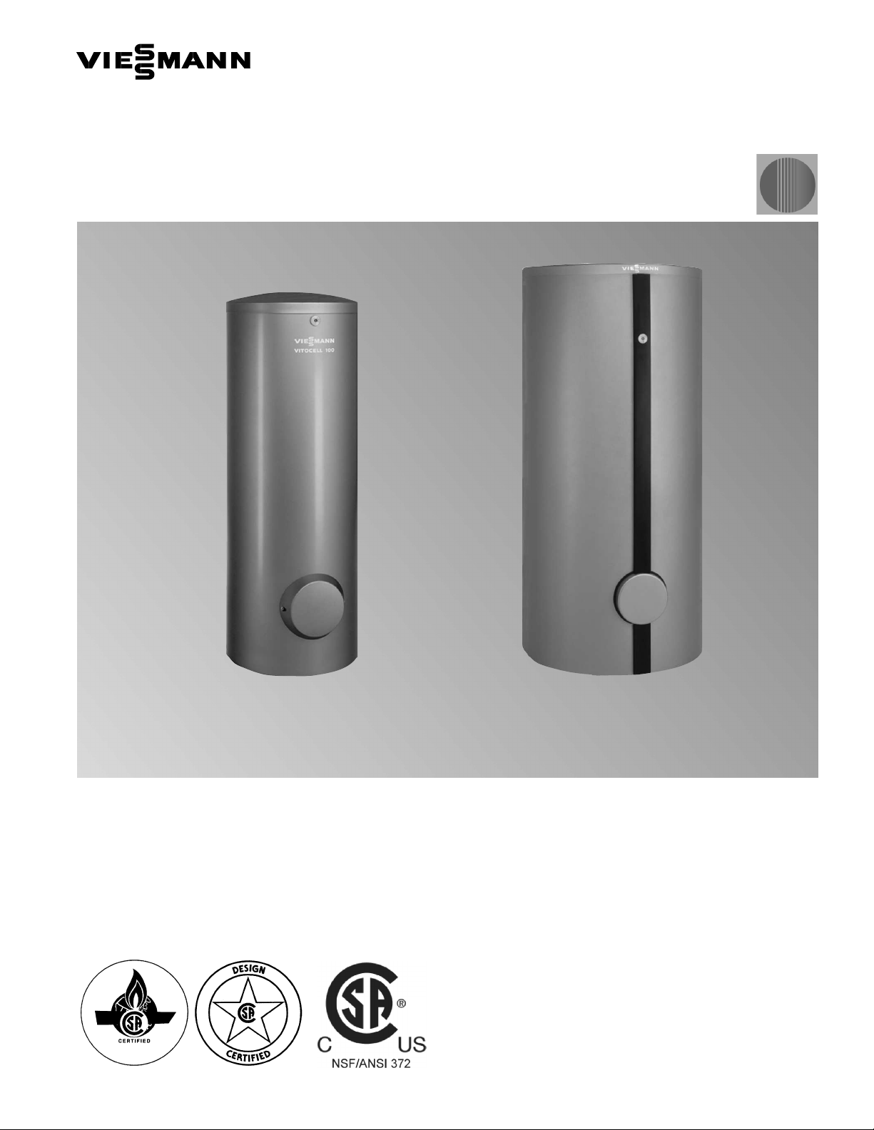
VVVVIIIITTTTOOOOCCCCEEEELLLLLLLL111100000000----VVVV
Indirect-fired domestic hot water storage tank
42 to 119 USG / 160 to 450 ltr
Vitocell-V 100
42 to 79 USG / 160 to 300 ltr
Product may not be exactly as shown
Vitocell 100-V
CVA Series
Indirect-fired domestic hot water storage tank
steel construction, with Ceraprotect two-coat enamel finish
5167 518 - 01 03/2014
Vitocell-V 100
119 USG / 450 ltr
Page 2

Product Information
5
1
6
7
5
1
8
-
0
1
VVVVIIIITTTTOOOOCCCCEEEELLLLLLLL 111100000000----VVVV
The vertical tank solution for cost-efficient
domestic hot water supply. The
Vitocell 100-V DHW tank offers storage
capacities of up to 119 USG / 450 ltrs.
The benefits at a glance:
H Corrosion-protected steel tank shell with
Ceraprotect two-coat enamel finish.
Magnesium anode provides additional
cathodic tank protection.
H Heat exchanger coil extends to the bottom
of the tank, thereby heating the entire
water content.
H Extremely convenient domestic hot water
supply assured by fast, uniform heating
via generously sized heat exchanger
surfaces.
H Certified to CSA Low Lead Content
Certification Program;
including US Safe Drinking Water Act,
NSF/ANSI 372 as well as other applicable
US State requirements.
H Universally suitable - for applications
requiring larger quantities of hot water,
multiple Vitocell 100-V tanks may be
connected to a header to form a tank
battery.
H Increased energy savings thanks to highly
effective, foamed-in-place HCFC-free
insulation keeping standby losses at a
minimum.
H The vitocell-V 100 119 USG / 450 L
capacity tank is supplied with removable
soft PET insulation for easier handling.
2 VITOCELL 100-V
2
Page 3
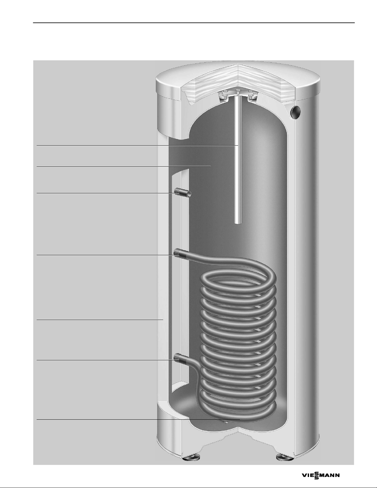
Magnesium anode
5
1
6
7
5
1
8
-
0
1
Steel domestic hot water storage tank,
with Ceraprotect two-coat enamel finish
Recirculation tapping
Product Information
Cross-Section
Boiler water supply
2¼”/58 mm PUR Foam or 4”/100 mm
wrap-around PET insulation (HCFC-free)
Boiler water return
Non-finned tubular steel heat exchanger coil with
Ceraprotect finish extends to tank bottom the entire water volume is heated, preventing
cold spots where bacteria growth could occur
Product may not be exactly as illustrated.
VITOCELL 100-V
3
Page 4
Technical Data
ofthedomesticho
t
andboilerwatersuppl
y
below
ofthedomesticho
t
andboilerwatersuppl
y
Domesticcold/hotwater
T&Pvalv
e
”(malethread)¾¾¾1¾1
¼
¾
T&Pvalv
e
∅
”(femalethread)
¾
¾¾¾1¾
5
1
6
7
5
1
8
-
0
1
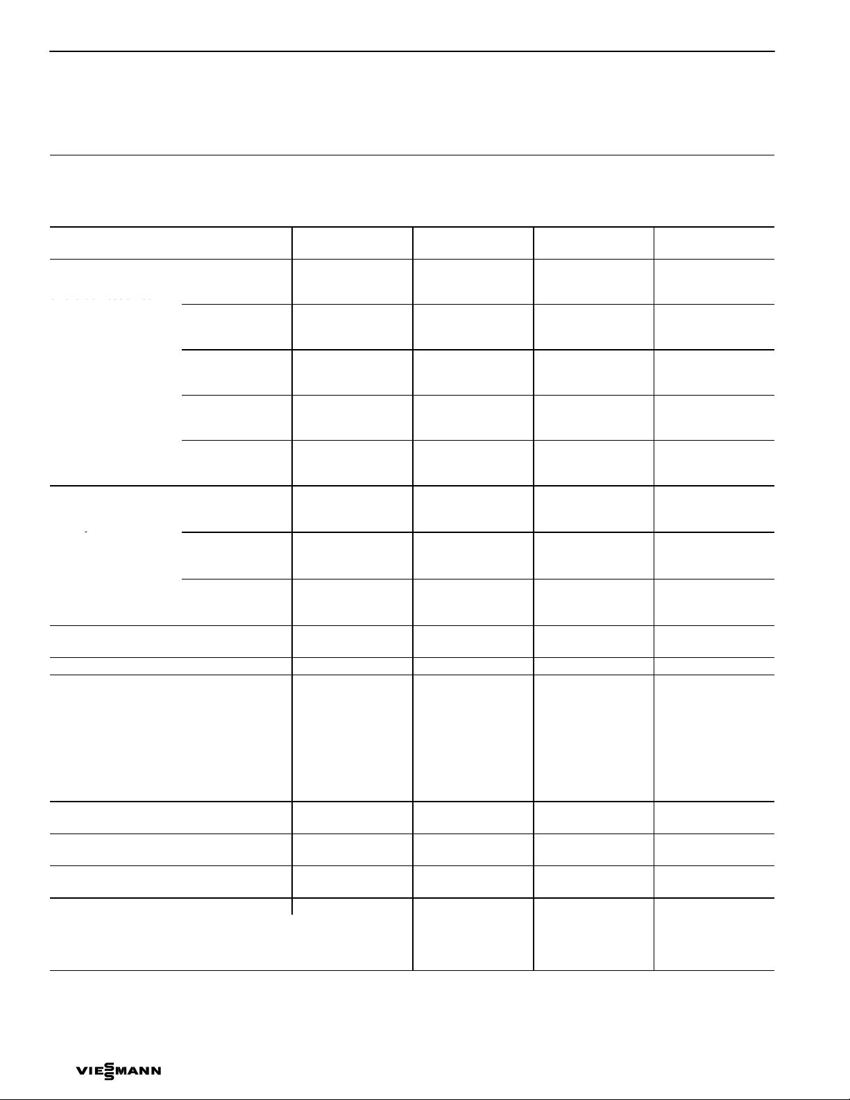
Technical Data
For domestic hot water heating applications in Suitable for heating systems with
conjunction with hot water heating boilers H max. working pressure on the heat exchanger side of up to 150 psig / 10 bar
Storage Capacity USG
ltr
Recovery rate
*1
with a temperature rise
of the domestic hot
water from
50 to 113 °F /
10 to 45 °C
temperature of.... at the
supply flow rate stated
Recovery rate
*1
with a temperature rise
of the domestic hot
water from
50 to 140 °F /
10 to 60 °C
temperature of.... at the
supply flow rate stated
below
Supply flow rate for the
recovery rates stated
Standby losses
*2
194 °F
176 °F
158 °F
140 °F
122 °F
194 °F
176 °F
158 °F
MBH
GPM
90 °C
ltr/h
MBH
GPM
80 °C
ltr/h
MBH
GPM
70 °C
ltr/h
MBH
GPM
60 °C
ltr/h
MBH
GPM
50 °C
ltr/h
MBH
GPM
90 °C
ltr/h
MBH
GPM
80 °C
ltr/h
MBH
GPM
70 °C
ltr/h
GPM
m3/h
MBH/24 h 5.1 5.8 7.5 9.6
Overall dimensions with insulation
Width (∅) inches
mm
Depth inches
mm
Height inches
mm
Tilt height inches
mm
Weight
Tank with insulation
lbs
kg
Heating water content USG
ltr
Heat exchanger surface area ft.
2
2
m
Connections
Heating water supply/return
∅” (male thread) 1
∅
H max. working pressure on DHW side of up to 150 psig / 10 bar
H max. supply temperature on the heat exchanger side of up to 230 °F / 110 °C
H max. DHW supply temperature of up to 150 °F / 65.6 °C
42
160
136
4.3
982
109
3.5
786
85
2.7
614
58
1.8
417
31
1
221
123
2.7
619
95
2
482
65
1.4
327
13.2
3.0
23
581
24
608
47
1189
50
1260
190
86
1.45
5.5
10.8
1
53
200
136
4.3
982
109
3.5
786
85
2.7
614
58
1.8
417
31
221
123
2.7
619
95
482
65
1.4
327
13.2
3.0
23
581
24
608
55½
1409
57½
1460
214
97
1.45
5.5
10.8
79
300
180
5.7
1302
1720
150
4.8
1081
1425
113
3.6
811
1106
78
0.3
565
61
1
1.9
442
153
3.4
774
116
2
2.6
584
78
1.7
395
13.2
3.0
25
633
27¾
705
68¾
1746
1955
70½
1792
1860
333
151
2.6
10
16.1
1
1
1.5
1
119
450
238
7.6
198
6.3
153
4.9
109
3.5
786
82
2.6
589
181
4
911
150
3.3
756
113
2.5
567
13.2
3.0
33½
850
35¼
898
77
73¼
399
181
3.3
12.5
20.5
1.9
1
Recirculation
*1
When planning for the recovery rate as stated or calculated, allow for the corresponding circulation pump. The stated recovery rate is
∅” (male thread) ¾
only achieved when the rated output of the boiler is equal to or greater than that stated under “Recovery rate”.
Please also refer to the corresponding sizing chart at the end of this manual.
*2
Measured values are based on a room temp. of 68°F / 20 ºC and a domestic hot water temp. of 149°F / 65 ºC and can vary by 5%.
4 VITOCELL 100-V
4
1
Page 5
Technical Data
5
1
6
7
5
1
8
-
0
1
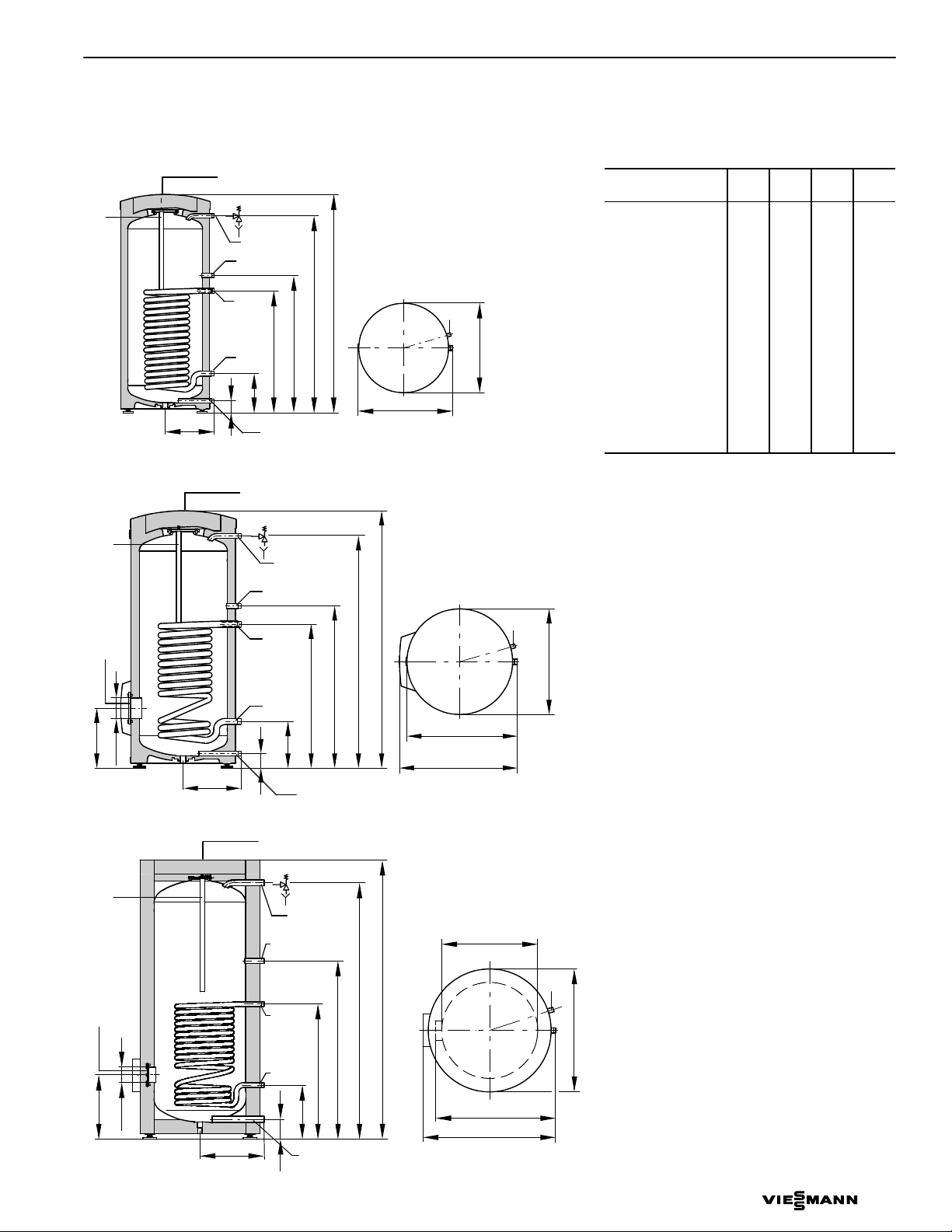
Vitocel 100l-V (42 and 53 USG / 160 and 200 ltr)
IO
MA
h
BWS
b
TPV
DHW
RT
BWR
c
e
d
DCW/D
f
Overall height
Overall depth
Vitocell 100-V (79 USG / 300 ltr)
IO
TPV
MA
DHW
RT
IO
a
j
h
BWS
BWR
b
c
DCW/D
f
Overall height
e
d
Overall depth
AQ
Dimensions
Storage
capacity
a
b
c
d
e
f
Overall width
AQ
Overall width
g
g
h
j Ø
Legend
IO Inspection and clean-out opening
D Drain
BWR Boiler water return
BWS Boiler water supply
DCW Domestic cold water
AQ Aquastat well
MA Magnesium anode
DHW Domestic hot water
RT Recirculation tapping
TPV Temperature and pressure relief
USG
ltr
inches
mm
inches
mm
inches
mm
inches
mm
inches
mm
inches
mm
inches
mm
inches
mm
inches
mm
(at same height as boiler water
supply connection)
valve
42
1605320079300
––
––
––
––
2¾
2¾
72
72
9¾
9¾
249
249
25
35
41
––
––
––
––
25
634
35
884
41
1270
––
––
12½
317
––
––
634
884
1050
12½
317
13
336
76
10
260
34½
875
44
1115
63
1600
26
660
13½
343
4½
114
119
450
16½
422
3
4
107
13¾
349
36¼
924
48½
1230
70¼
1784
33
837
18
455
4½
114
Vitocell 100-V (119 USG / 450 ltr)
IO
MA
DHW
RT
IO
a
j
VITOCELL 100-V
BWS
BWR
c
b
h
DCW/D
f
Overall height
e
d
Ø 25½” / 650 mm
AQ
Overall width
g
Overall depth
5
Page 6

Technical Data
5
1
6
7
5
1
8
-
0
1
Domestic hot water draw rate
Storage tank contents heated to 140 °F / 60 °C, boiler not reheating
Storage capacity USG
ltr
DHW draw rate GPM
ltr/min
Domestic hot water draw
Water with t = 140 °F /
USG
ltr
60 °C (constant)
Percentage tank volume 75% 73% 80% 93%
Heat-up time
The stated heating times are achieved when the maximum recovery rate of the domestic hot water tank is made available at the respective
supply temperature and with a domestic hot water rise from 50 to 140 °F / 10 to 60 °C.
Storage capacity USG
Heating water supply temperature Heat-up time (minutes)
194 °F / 90 °C
176 °F / 80 °C
158 °F / 70 °C
ltr
42
160
2.6
10
32
120
42
160
19
24
34
53
200
2.6
10
38
145
53
200
19
24
37
79
300
4.0
15
63
240
79
300
23
31
45
119
450
4.0
15
111
420
119
450
28
36
50
Pressure drop on heating water side (primary circuit) Pressure drop on domestic hot water side
(secondary circuit)
“w.c.
80 200
40 100
32 80
24 60
20 50
16 40
12 30
8 20
4 10
mbar
“ w.c.
mbar
40 100
32 80
24 60
20 50
16 40
12 30
8 20
4 10
3.2 8
2.4 6
2 5
1.6 4
1.2 3
0.8 2
200 500
160 400
120 300
3.2 8
2.4 6
2 5
1.6 4
Pressure drop
9 2 000
13 3 000
18 4 000
22 5 000
26 6 000
2.2 500
2.6 600
3.5 800
4.4 1 000
Flow rate
6 VITOCELL 100-V
6
31 7 000
ltr/h
GPM
0.4 1
Pressure drop
8
10
2.2133.5174.4
2.6
Flow rate
33
8.8
50
13
67
18
83
22
42 USG / 160 ltr and 53 USG / 200 ltr storage capacities
79 USG / 300 ltr storage capacity
119 USG / 450 ltr storage capacity
100
26
ltr/min
GPM
Page 7

Multiple Tank Installation (79 and 119 USG / 300 and 450 ltr only)
ofthedomesticho
t
andboilerwatersuppl
y
statedbelow
ofthedomesticho
t
andboilerwatersuppl
y
5
1
6
7
5
1
8
-
0
1
Technical Data
The 79 and 119 USG / 300 and 450 ltr tank sizes may be combined into a battery consisting of between 2 and 4 tanks.
Tank batteries consisting of more than 4 tanks can be installed by creating up to 4 batteries, each consisting of 4 tanks. The heating
contractor is responsible to ensure proper piping on both the primary and secondary circuits.
Tank storage capacity USG
ltr
Total capacity of tank battery USG
ltr
Number of storage tanks 2
Recovery rate
*1
with a temperature rise
of the domestic hot
water from
50 to 113 °F /
10 to 45 °C
temperature of .....
at the supply flow rate
Recovery rate
*1
with a temperature rise
of the domestic hot
water from
50 to 140 °F /
10 to 60 °C
temperature of .....
at the supply flow rate
stated below
Supply flow rate
for the recovery rates
194 °F
176 °F
158 °F
140 °F
122 °F
194 °F
176 °F
158 °F
90 °C
80 °C
70 °C
60 °C
50 °C
90 °C
80 °C
70 °C
MBH
GPM
ltr/h
MBH
GPM
ltr/h
MBH
GPM
ltr/h
MBH
GPM
ltr/h
MBH
GPM
ltr/h
MBH
GPM
ltr/h
MBH
GPM
ltr/h
MBH
GPM
ltr/h
GPM
m3/h
stated
Standby losses
*2
MBH/24 h 15 19.2 28.8 38.4
Overall dimensions with insulation
Overall width inches
mm
Overall depth inches
mm
Overall height inches
mm
Weight
Tank with insulation
Heating water content
(heat exchanger pipe coil)
Heat exchanger surface area ft.
*1
When planning for the recovery rate as stated or calculated, allow for the corresponding circulation pump. The stated recovery rate is
lbs
kg
USG
ltr
2
2
m
only achieved when the rated output of the boiler is equal to or greater than that stated under “Recovery rate”.
Please also refer to the corresponding sizing chart at the end of this manual.
*2
Measured values are based on a room temperature of 68°F / 20 ºC and a domestic hot water temperature of 149°F / 65 ºC and can
vary by 5%.
79
300
159
600
FF
361
11.5
2604
300
9.5
2162
225
7.1
1622
157
1130
123
3.9
884
307
6.8
1548
232
5.1
1168
157
3.5
790
26.4
57½
1461
43½
1109
69
1752
736¼
334
6½
25
32¼
3.0
119
450
238
900
2
FF
477
15.1
3440
396
12.5
2850
307
9.7
2212
218
5
6.9
1572
164
5.2
1178
361
8.0
1822
300
6.7
1512
225
5.0
1134
26.4
6
6
72½
1838
48
1218
77
1955
932
423
8½
32
42
3.9
357
1350
3
FFF
716
22.7
5160
593
18.8
4275
460
14.6
3318
327
10.4
2358
246
7.8
1767
542
12.0
2733
450
10.0
2268
338
7.5
1701
39.6
9
111¼
2826
48
1218
77
1955
1409
639
13¾
50
62½
5.8
476
1800
4
FFFF
955
30.3
6880
791
25.1
5700
614
19.5
4424
436
13.8
3144
327
10.4
2356
723
16.0
3644
600
13.3
3024
450
10.0
2268
50.8
12
150
3814
48¾
1237
77
1955
1913
868
20¾
79
84
7.8
VITOCELL 100-V
7
Page 8

Multiple Tank Installation (79 and 119 USG / 300 and 450 ltr only)
5
1
6
7
5
1
8
-
0
1
For domestic hot water applications which
utilize modulating and low temperature hot water
heating boilers or remote heating plants
Qty 2 Qty 3 Qty 4
IO
DHW
TPV
RT
A
BWS
IO
e
Side view Top view
Legend
IO Inspection and clean-out opening
D Drain
A Air vent
Dimensions
Storage capacity USG
Total capacity of battery
Number of storage tanks
a
b
c
d
e
h
BWR
DHW/
D
ltr
USG
ltr
inches
mm
inches
mm
inches
mm
inches
mm
inches
mm
inches
mm
a
d
c
Width
b
BWR Boiler water return
BWS Boiler water supply
DCW Domestic cold water
79
300
159
600
76
10¼
260
34½
875
63
1600
16½
343
206
Depth
2
3
8
h h
BWR
BWS
Width
238
900
4¼
107
13¾
349
36¼
924
70¼
1784
455
12½
315
BWR
A
BWS
h h
Depth
DHW Domestic hot water
RT Recirculation tapping
TPV T&P valve
2
18
Width
119
450
357
1350
4¼
107
13¾
349
36¼
924
70¼
1784
18
455
12½
315
hh
BWR
AA
BWS
Depth
476
3
1800
4
4¼
107
13¾
349
36¼
924
70¼
1784
18
455
12½
315
8 VITOCELL 100-V
8
Page 9

Multilple Tank Installation (79 and 119 USG / 300 and 450 ltr only)
5
1
6
7
5
1
8
-
0
1
Domestic hot water draw rate
Storage tank content heated to 140 °F / 60 °C
Storage capacity USG
Battery storage capacity
Number of tanks
DHW draw rate GPM
Domestic hot water draw
Water with t = 140 °F /
60 °C (constant)
Percentage of battery volume 80% 84% 84% 84%
ltr
USG
ltr
ltr/min
USG
ltr
Quick recovery (over 10-minute period)
Domestic hot water rise from 50 to 113 °F / 10 to 45 °C
Storage capacity USG
Battery storage capacity
Number of tanks
Heating water supply temperature Quick DHW recovery (over 10-minute period)
194 °F / 90 °C
176 °F / 80 °C
158 °F / 70 °C
ltr
USG
ltr
USG/10 min
ltr/10 min
USG/10 min
ltr/10 min
USG/10 min
ltr/10 min
79
300
159
600
7.9
30
127
480
2
79
300
159
600
201
759
197
745
192
728
119
450
238
900
2
7.9
30
222
840
238
2
900
2
317
1200
310
1175
284
1075
357
1350
7.9
30
333
1260
119
450
357
1350
441
1670
431
1630
396
1498
476
1800
3
11.9
45
444
1680
476
1800
3
540
2045
502
1900
478
1810
4
4
Max. domestic hot water draw rate (over 10-minute period)
Domestic hot water rise from 50 to 113 °F / 10 to 45 °C
Storage capacity USG
Battery storage capacity
Number of tanks
Heating water supply temperature Max. DHW draw rate (over 10-minute period)
194 °F / 90 °C
176 °F / 80 °C
158 °F / 70 °C
ltr
USG
ltr
GPM
ltr/min
GPM
ltr/min
GPM
ltr/min
79
300
159
600
20.1
76
20
74
19.3
73
119
450
238
2
900
2
32
120
31.3
118
28.4
107
357
1350
44.1
167
43.2
163
150
40
476
3
1800
4
54
204
50.4
190
48
181
VITOCELL 100-V
9
Page 10

Standard Equipment
5
1
6
7
5
1
8
-
0
1
Product Installation
Standard Equipment
Vitocell 100-V
42 to 79 USG / 160 to 300 ltr capacity
Domestic hot water storage tank of
high-grade steel with PUR Foam insulation
(HCFC-free) and Ceraprotect two-coat
enamel finish with:
H thermometer
H adjustable leveling feet
H built-in aquastat well
H Magnesium anode
The following is packed separately and
attached to the crate:
H installation fittings package: with the
necessary brass adaptors, other necessary
hardware, and hemp
H temperature and pressure relief valve.
Electrostatically powder-coated sheet metal
enclosure panel in a Vitosilver finish.
Domestic hot water connections
Vitocell 100-V
119 USG / 450 ltr capacity
Domestic hot water storage tank of
high-grade steel with wrap-around soft PET
insulation (HCFC-free) and Ceraprotect
two-coat enamel finish with:
H thermometer
H adjustable leveling feet
H built-in aquastat well
H Magnesium anode
The following is packed separately and
attached to the crate:
H installation fittings package: with the
necessary brass adaptors, other necessary
hardware, and hemp
H temperature and pressure relief valve.
Synthetic wrap-around enclosure panel in a
Vitosilver finish.
IMPORTANT
This is a simplified conceptual drawing
only! Piping and necessary componentry
must be field verified. Proper installation
and functionality in the field is the
responsibility of the heating contractor.
Domestic hot water supply
DHW recirculation line
DHW recirculation pump
Spring-loaded flow check valve
Discharge pipe
Temperature and pressure relief valve
(TPV)
Shut-off valve
Drain
Domestic cold water supply lines
Backflow preventer
Domestic cold water inlet
Precharged expansion tank
(required where backflow preventer
is installed; check local plumbing
codes and requirements)
Thermostatic mixing valve/anti-scald
valve for solar applications
(field
supplied)
10 VITOCELL 100-V
10
Page 11

Product Installation
5
1
6
7
5
1
8
-
0
1
Backflow preventers
Where backflow preventers are required, a
domestic water expansion tank installation
is recommended in the cold water inlet
piping before the cold water enters the
Vitocell. For the backflow device, observe
local plumbing codes and regulations.
Temperature and pressure
relief valve
A temperature and pressure relief valve
(T&P relief valve) is supplied with the tank.
The heating contractor must install the
valve on each tank in a method meeting
code requirements. If local codes require a
different relief valve, substitute the
manufacturer’s supplied valve. The tank is
approved for 150 psig. Maximum operating
pressure is 150 psig.
The T&P relief valve supplied with the tank
is tested under ANSI Z21.22 Code for Relief
Valves and Automatic Gas Shut-off Devices
for Hot Water Supply Systems.
IMPORTANT
Since the heat exchanger coil allows for
high MBH input (see Vitocell flow charts),
confirmation that the appropriate and
correct size pressure and temperature relief
valve is used and installed, is necessary.
Warranty
Our warranty for domestic hot water tanks
states that the water heated must be of
drinking (potable) water quality and that any
water treatment equipment in use must
function correctly.
Viessmann accepts no responsibility for
damage howsoever caused and reserves the
right to withdraw the product warranty if the
product has been improperly installed or
misapplied by the installer, contractor or final
user. In order to qualify for product warranty,
strict adherence to the installation and
service manuals must be assured. In the
event that Viessmann non-approved
components are utilized, Viessmann reserves
the right to withdraw all expressed or implied
warranties without written notice.
The water to be heated with the Vitocell
must be drinking (potable) water quality. If
the tank is used to heat other media, the
warranty will be null and void. Damage
resulting from excessive pressure or
temperature is clearly not the responsibility
of Viessmann.
The amount of chloride and sulfate
acceptable to the tank is limited. In areas
where high concentrations of chloride and
sulfate are present in drinking water, please
consult Viessmann for directions.
Sensor Well
Vitocell 100-V
42 to 119 USG / 160 to 450 ltr capacity
The sensor well is welded into the domestic
hot water storage tank.
Ø ½”/
14.9 mm
21.3 mm
Ø ¾”/
8” / 200 mm
Watts Model
40XL-8
ASME pressure
steam rating
CSA temperature
steam rating
Relief
temperature
Inlet thread
Outlet thread
VITOCELL 100-V
150 psig
(US and Canada)
1438 MBH
205 MBH
210ºF (99ºC)
¾” male
¾” female
11
Page 12

Vitocell 100-V Sizing
5
1
6
7
5
1
8
-
0
1
Continuous Flow Capacity Chart
Vitocell 100-V,
42 and 53 USG / 160 and 200 ltr capacities
Curve
Domestic hot water 40 to 113°F / 4 to 45°C
Curve
Domestic hot water 40 to 140°F / 4 to 60°C
12 VITOCELL 100-V
12
Page 13

Vitocell 100-V,
5
1
6
7
5
1
8
-
0
1
79 USG / 300 ltr capacity
Curve
Domestic hot water 40 to 113°F / 4 to 45°C
Curve
Domestic hot water 40 to 140°F / 4 to 60°C
Vitocell 100-V Sizing
Continuous Flow Capacity Chart
VITOCELL 100-V
13
Page 14

Vitocell 100-V Sizing
5
1
6
7
5
1
8
-
0
1
Continuous Flow Capacity Chart
Vitocell 100-V,
119 USG / 450 ltr capacity
Curve
Domestic hot water 40 to 113°F / 4 to 45°C
Curve
Domestic hot water 40 to 140°F / 4 to 60°C
14 VITOCELL 100-V
14
Page 15

Vitocell 100-V Sizing
5
1
6
7
5
1
8
-
0
1
Continuous Flow Capacity Chart
Example: Vitocell 100-V, 119 USG / 450 ltr capacity
Assume boiler output to tank is 170 MBH. Enter chart at left and draw horizontal line across to recovery rate of 203 GPH / 3.4 GPM for
140°F / 60°C domestic hot water under column B. Where the horizontal line intersects the 194°F / 90°C curve is the point of intersection
for the diagonal line used to size the pump. The diagonal line begins at the origin and goes through the point of intersection extending up
to the top of the chart. Read between the reference diagonal lines to get a pump specification of 11.9 GPM at 5 ft. To summarize: For a
Vitocell-V 100 with 119 USG / 450 ltr capacity and 170 MBH input, the boiler water temperature is 194°F / 90°C, difference between
boiler return and supply water temperature is 31°F / 17°C, recovery rate is 3.4 GPM of 140°F / 60°C DHW, and the pump required is
11.9 GPM, 5.0 ft. plus pressure drop in piping and boiler.
VITOCELL 100-V
15
Page 16

Printed on environmentally friendly
5
1
6
7
5
1
8
-
0
1
(recycled and recyclable) paper.
16 VITOCELL 100-V
16
Technical information subject to change without notice.
 Loading...