

Page 1
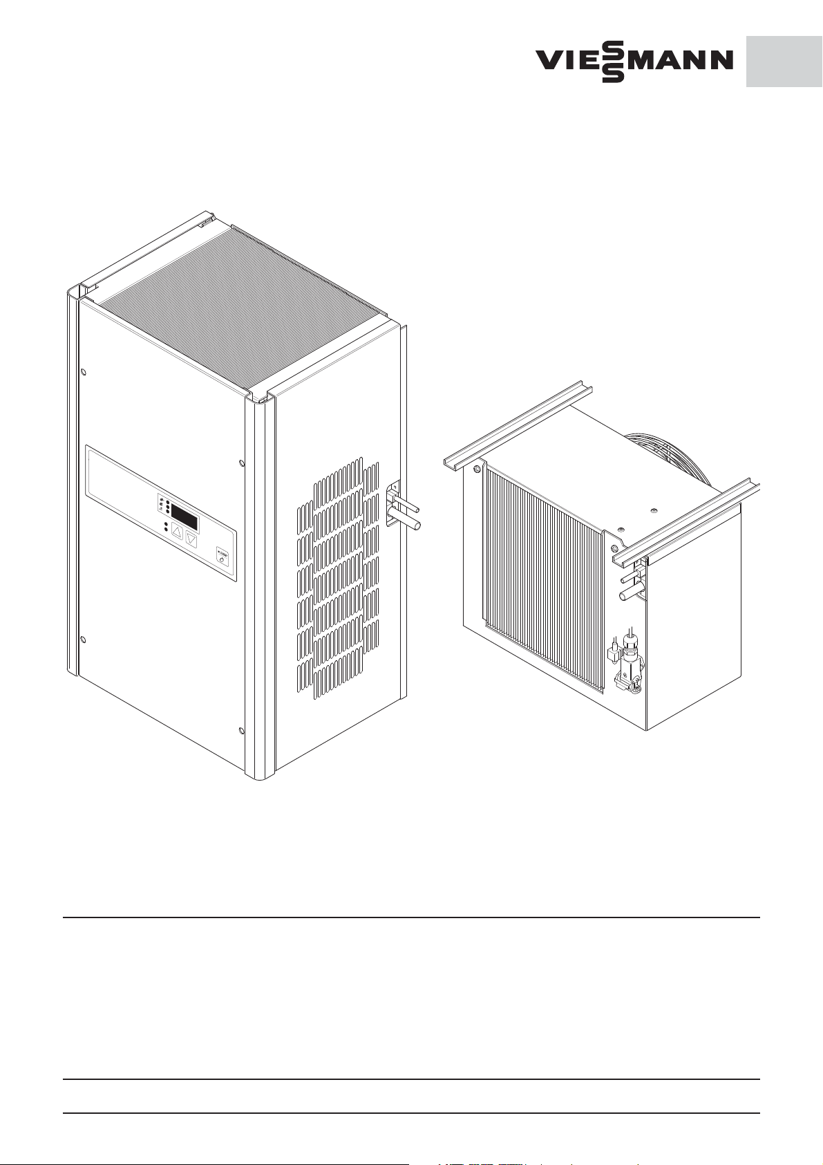
Split refrigeration units
GB
Assembly manual
5237211-09 GB
Please read carefully the following prior to beginning work on the refrigeration unit:
Assembly, maintenance, cleaning and repair may only be Work on the refrigeration unit may only be carried out if the
done by companies specialising in cooling technology. plug is removed from the power supply. Suitable warnings
Technical changes and manipulation are prohibited. must be posted to prevent the refrigeration unit from being
restarted while work is in progress. The regulations of VDE
In case of non-compliance our guarantees are void. 0105 Part 1 - for work on electrical equipment must be
obser ved.
General notice (liability): the details of this technical documents serve for description. Consents regarding the availability of certain features or
regarding a certain purpose always require a special written agreement.
Page No. 5237320-09 GB Right reserved to make technical changes! Version 02.14
Page 2

GB
Table of contents
1. General notes
1.1 Extract from the conditions of guarantee
1.2 Requirements for installation area
1.3 Transport
1.4 Supplied condition
1.5 Unpacking and handling
1.6 Cleaning and maintenance of the refrigeration unit
2. Installation of the refrigeration unit in a Viessmann coldroom
2.1 Assembly of the condensation unit
2.1.1 Drilling diagram for fastening the large condensation unit
2.1.2 Drilling diagram for fastening the small condensation unit
2.2 Assembly of the evaporation unit
2.2.1 Drilling diagram for fastening the large evaporation unit
2.2.2 Drilling diagram for fastening the small evaporation unit
2.3 Installation of pipes
2.4 Installation of electrical cables
2.5 Assembly of the condensate run-off tubing
3. Electrical power supply to the coldroom
3.1 Power supply
3.2 Pre installed socket (Only refrigeration units FS 1800 and FS 2400)
3.3 Connecting the door contact switch
3.3.1 Electronic control SE
3.4 Connecting the alarm
3.5 Connecting remote and central controls
3.6 Connector diagram for electronic control SE
General notice (liability): the details of this technical documents serve for description. Consents regarding the availability of certain features or
regarding a certain purpose always require a special written agreement.
Page No. 5237321-07 GB Contents Right reserved to make technical changes!
Page 3

1. General notes
GB
1.1 Extract from the conditions of guarantee
No guarantee is assumed for damage resulting from
improper use, improper assembly or operation by the
buyer or other parties, natural wear, improper or negligent
handling, or chemical/electro chemical influence, insofar as
this is not our fault, or resulting from in attention to the
assembly, operating and maintenance instructions,
improper alterations or maintenance done by the buyer or
third parties, or as a result of use of parts supplied by other
manufacturers.
1.2 Requirements for installation area / Intended use
For economical operation of the refrigeration unit, the
ambient temperature should be between +5°C to +25°C.
The room must be well ventilated to remove heat
generated. Direct heat radiation on the refrigeration unit
must be avoided. Heating the room must also be avoided,
otherwise the comsumption of electrical power will
increase.
lf installed outdoors, a roof must be provided.
lf ambient temperature is below 10°C an oil heating is to be
installed. Viessmann can supply this as an optional
accessory.
The refrigeration unit is designed to provide free access in
regard to suction and release of air. lf air ducts are required,
these must be designed and installed by a cooling
specialist company.
There must be enough space in front of the suction and air
release vents of the refrigeration unit to guarantee proper
ventilation:
- at least 250 mm in front of all suction and air release
vents
Do not install units in plants where there is a danger
of fire.
According to DIN VDE 0100-482 (VDE 0100 Part 482):
1997-08 these are rooms or places in rooms or out doors
where there is a danger that, depending on the local and
plant conditions, esily flammable materials in dangerous
quantities could be close enough to the electrical
equipment such that higher temperatures or electrical
sparks could cause fire. These could be: work or drying
areas, storerooms, or parts of room, as well as such areas
outdoors, e.g. paper, wood, textile or wood working plants,
hay, straw, jute, and flax storing areas.
- According to BGR 500, chapter 2.35 or local regulations
for operation and maintenance. (qualified staff)
1.3 Transport
Because of the oil in the condenser, the refrigeration
unit may only be transported in a standing position. lf
the unit is to be transported further, only the original
packing may be used.
1.4 Supplied condition
The refrigeration unit is delivered ready for operation,
with wire and plug, packed in a carton.
1.5 Unpacking and handling
- Prior to and during unpacking of the refrigeration
unit, visual inspection must be carried out to check
if any damage occurred during transportation.
- Please inspect for loose parts, dents, scratches,
visible loss of oil, etc.
- During handling, the unit should be gripped only
on the housing or on the frame.
- Prior to disposing of the packing, it should be
inspected for presence of loose parts.
- To process any claims, we require an exact
description of the problem (with picture), as well as
the designation and serial number of the unit.
- To prevent damaging of the unit, it may only be
transported and stored in the position of use. Non
compliance will cause loss of guarantee protection.
General notice (liability): the details of this technical documents serve for description. Consents regarding the availability of certain features or
regarding a certain purpose always require a special written agreement.
Page No. 5237322-06 GB 1 - 1.5 Right reserved to make technical changes!
Page 4

GB
1.6 Cleaning and maintenance of the refrigeration unit
During cleaning the refrigeration unit and the coldroom
should be cut off from the power supply.
Remove the plug from the power supply during such
work and secure against the plug being reinserted, or
switch off the power supply at source and secure
against switching on.
- The cooling unit should be inspected periodically after
beginning operation and, if necessary, cleaned.
Depending on requirements, the intervals between
inspection and cleaning have to be determined.The
cleaning intervals depend on the condition of the
surroundings.
- The condenser and evaporator can be cleaned with a
soft brush, compressed air or, in case of oil residues,
with a high pressure cleaner. Do not use any sharp or
pointed objects. The fins should not be bent or
damaged during cleaning.
By courtesy of intensive contamination with solvents or
outgasing synthetics natural discolorations can appear
on the SilverProtec surface. These are unproblematicly
removable with common purifiers based on oxygen or
with bleaching agents with a reaction time conforming
to the gravity of discoloration. The purifiers Vanish
Oxiaction from Hoffmanns or Sil OXIperfect from Henkel
perform well. Both products are available in trade. For
the cleaning of vertical areas on which the sprayed
purifier would slide down without a reaction time, we
recommend to spray the purifier on a cleaning rag and
then press it slightly on the discoloured spot so that the
rag doesn‘t slip off. Remove the rag after the reaction
time and wipe the treated spot again.
Pay attention to the product information!
General notice (liability): the details of this technical documents serve for description. Consents regarding the availability of certain features or
regarding a certain purpose always require a special written agreement.
Page No. 5237313-01 GB 1.6 Right reserved to make technical changes!
Page 5

2. Installation of a refrigeration unit
in a Viessmann coldroom
2.1 Assembly of the condenser unit
The condenser unit is assembled outside of the coldroom.
The length of the electric cable on the evaporation unit is
15 m, including plug. This is also the maximum distance
between condenser and evaporator.
The minimum distance to the ceiling must be 250 mm to
guarantee proper ventilation
Attention!
This minimum distance must be checked prior to
assembly of the evaporator!
GB
Attention!
The assembly and installation of a split unit must be
done by an approved specialist!
Release the locking screws on the front panel (4).
Remove front panel.
Anchor the evaporation unit on the drill holes provides at
the back of the unit on the wall using the anchoring
material provided.
General notice (liability): the details of this technical documents serve for description. Consents regarding the availability of certain features or
regarding a certain purpose always require a special written agreement.
Page No. 5237323-06 GB 2 - 2.1 Right reserved to make technical changes!
Page 6

GB
2.1.1 Drilling diagram for fastening the large condensation unit
(CS 2000, CS 2800, FS 1400, FS 1800, FS 2400)
Ceiling
Distance to wall 60 mm.
2.1.2 Drilling diagram for fastening the small condensation unit
(CS 0900, CS 1300, FS 0900)
Distance to wall 60 mm
240 mm
Wall
Conections for
refrigerant and electro
min. 60 mm
220 mm
600 mm
420 mm
12 mm
Two drill holes
with 12 mm
lines to the evaporator
Ceiling
427 mm
Two drill holes
with 12 mm
240 mm
12 mm
min.
390 mm
94 mm
250 mm
850 mm
290 mm
min.
250 mm
Wall
Conections for
refrigerant and electro
lines to the evaporator
min. 60 mm
700 mm
94 mm
General notice (liability): the details of this technical documents serve for description. Consents regarding the availability of certain features or
regarding a certain purpose always require a special written agreement.
Page No. 5237334-05 GB 2.1.1 - 2.1.2 Right reserved to make technical changes!
Page 7

2.2 Assembly of the evaporation unit
The evaporator is assembled within the coldroom on the
ceiling.
Using the two drawings 2.2.1 and 2.2.2 four holes are drilled
on the ceiling.
Cut edges should be rust proofed.
Anchor evaporation unit with enclosed plastic scres on the
U-profiles on the coldroom ceiling.
2.2.1 Drilling diagram for large evaporation unit
(CS 2000, CS 2800, FS 1400, FS 1800, FS 2400)
GB
min. 35 min. 80
Distance to wall 140 mm for wall thickness 150 mm.
Distance to wall 230 mm for wall thickness 60 mm.
2.2.2 Drilling diagram for small evaporation unit
(CS 0900, CS 1300, FS 0900)
Distance to wall 165 mm for wall thickness 150 mm.
Distance to wall 255 mm for wall thickness 60 mm.
Exhaust vent
Ceiling
Wall
295 mm
Suction vent
475 mm
Distance to wall 140 - 230 mm
min. 15 min. 15
Exhaust vent
Ceiling
Wall
255 mm
Wall
ø 11 mm
Wall
Suctionvent
381 mm
Distance to wall 165 - 255 mm
General notice (liability): the details of this technical documents serve for description. Consents regarding the availability of certain features or
regarding a certain purpose always require a special written agreement.
Page No. 5237324-06 GB 2.2 - 2.2.2 Right reserved to make technical changes!
ø 11 mm
Page 8

GB
2.3 Installation of conduits
Solder the evaporator to the refrigeration unit at the points
(P and Q) on the refrigeration unit using a suitable copper
pipe with the soldering points on the evaporator.
Test all soldering points for sealing.
The length of the conduit may not exceed 15 m!
Pipe diameter in mm
Unit CS 900 CS 1300 CS 2000 CS 2800
Fluid Conduit (P) 6 6 6 10
Suction Pipe (Q) 10 12 12 16
Unit FS 900 FS 1400 FS 1800 FS 2400
Fluid Conduit (P) 6 10 10 10
Suction Pipe (Q) 12 16 16 16
P
Q
2.4 Laying electrical cables
The electrical cables should be laid along the pipes.
Insert the electrical plug into the proper socket on the
refrigeration unit template.
Attention!
Do not connect electrical power supply until beginning
of operation - Danger!
General notice (liability): the details of this technical documents serve for description. Consents regarding the availability of certain features or
regarding a certain purpose always require a special written agreement.
Page No. 5237325-06 GB 2.3 - 2.4 Right reserved to make technical changes!
Page 9

2.5 Assembly of the condensate run-off tubing
Place plastic ring (D) over the condensate run-off tubing (B).
Insert heating (A) in the condensate run-off tubing (B) which
should be straightened for easier insertion.
GB
D
B
Condensate run-off tubing (B) from inside through hole
(G, ø 31 mm) in the coldroom wall (F). If necessary, a
lubricant can be used.
Condensate run-off tubing (B) on the drain plug (E) of the
evaporation plate.
Cover hole (G) for condensate run-off tubing (B) with the
plastic ring (D).
See separate assembly notes for all split units regarding
pipe drain (H).
D
A
G
B
E
D
B
FH
General notice (liability): the details of this technical documents serve for description. Consents regarding the availability of certain features or
regarding a certain purpose always require a special written agreement.
Page No. 5237326-06 GB 2.5 Right reserved to make technical changes!
Page 10

GB
3. Electrical power supply to coldroom
The refrigeration unit has a pre installed multiple pole socket
for electrical power supply in the coldroom for other
purposes (e.g. lighting, max. 250 Watt).
Attention!
Do not turn on electrical power until operation begins
danger to life!
3.1 Connection
Work on the electrical connections and protective devices
may only be undertaken by a specialist company according
to IEC 364, local regulations and the conditions of the
respective energy supply companies!
Insert plug only in a properly grounded socket.
(AC 230 V ~ 50 Hz)
Connector L1-4 must be removed over 0°C
Power supply
230 V ~, 50 Hz
L1
N
Multiple-pole
plug
Door switch
Pressure
compensator
with heating
(optional)
2
3
1
Distribut
A*
B*
C*
Door frame
heating
optional
2
4
L1
N
3
BK1
BK2
BK3
BK4
5
6
Coldroom
light
max.
60 W
1
Cable foamed into
door frame
BK5
Controls
Switch (2-polig)
with light display
for coldroom
light
Connection diagram for multiple-pole plug electrical power supply for coldroom (Viessmann freezer)
with door contact switch
Connector L1-4 must be removed over 0°C
Power supply
230 V ~, 50 Hz
L1
N
Multiple-pole
plug
Distribut
2
3
1
Door frame
heating
optional
4
2
A*
B*
C*
L1
N
3
BK1
BK2
BK3
BK4
Coldroom
light
1
Cable foamed into
door frame
BK5
max.
60 W
Controls
Pressure
compensator
with heating
(optional)
5
6
Switch (2-polig)
with light display
for Coldroom
light
Connection diagram for multiple-pole plug -
electrical power supply for coldroom (Viessmann freezer)
without door contact switch
Multiple-pole
plug
Connection diagramm for multiple-pole plug - door
contact switch (without electrical power supply for
Door switch
General notice (liability): the details of this technical documents serve for description. Consents regarding the availability of certain features or
regarding a certain purpose always require a special written agreement.
Page No. 5237307-06 GB 3 - 3.1 Right reserved to make technical changes!
Page 11

3.2 Installed plug
(Only refrigeration units FS 1800 and FS 2400)
Release the inside right hand screws on the right side section
(Y), push side section up and remove. Fix CEE plug (Q) on the
reverse side of the floor plate (Z) of the refrigeration unit
with the enclosed screws (J). Insert side section (Y) again,
push down and secure with screws.
Insert CEE coupling ( 5x16 A, AC 400 V 3 ~ 50 Hz) in CEE plug.
GB
Y
T
3.3 Connecting door contact switch
With coldroom door open, the evaporation ventilator should
be switched off. We recommend the installation of a switch
free of potential electricity.
Connection is made via the multiple pole socket on the
refrigeration unit.
In the condition supplied, the unit functions properly
without an external door contact switch.
3.3.1 Electronic control SE
lf a doorswitch is connected to the unit, the sliding switch
on the control must be moved to the position with
doorswitch).The switch can be reached after removing
the front panel.
J
Q
Z
General notice (liability): the details of this technical documents serve for description. Consents regarding the availability of certain features or
regarding a certain purpose always require a special written agreement.
Page No. 5237308-05 GB 3.2 - 3.3.1 Right reserved to make technical changes!
Page 12

GB
3.4 Connecting the alarm contact
The electronic control SE has a potential free alarm contact
to connect to an appropriate alarm (max. 10 A, AC 230 V ~).
The connection is on the back of the plate.
A3
CNCNO
A3
Plate
Contact plan:
Contacts CNC = Opener
Contacts CNO = Close
potential-free
Alarm
AC 10A/230 V
3.5 Connecting remote and central controls
The electronic control SE has a nine pole D Sub plug on the
back of the plate. The serial interface is the connection for
the remote control and can be connected to a central
controlsystem.
General notice (liability): the details of this technical documents serve for description. Consents regarding the availability of certain features or
regarding a certain purpose always require a special written agreement.
Page No. 5237329-05 GB 3.4 - 3.5 Right reserved to make technical changes!
Page 13

Liquely
Vent 1
A8
Condens
A6
Evaproate
Vent
A4
Defro
haeting
A2
Heating
230V / 50 Hz
E1
5 x 1
9 - pol.
D - Sub
ext.
Alarm
A3
Temp.sensor
GB
E2
A8
L1PEN
BN
GNYE
A8
M
~
1
BU
A9
A7
L1PEN
BN
GNYE
A7
BU
Oil
heating
A7
A6
L1PEN
BN
GNYE
A6
M
~
1
BU
P
Multi-Pole
lead
230V / 50 Hz
A5
321
BNBKBU
A5
214
A5
L1PEN
BN
A4
A4
M
1
GNYE
~
BU
A2
L1PEN
BN
GNYE
A2
Pressostat
BU
A1
A1
L1PEN
BK
GNYE
BU
T
BN
A1
Output 230 V/50 Hz
and door contact
E1
L1PEN
BN
GNYE
E1
BU
5 x 1
D - Sub
Socket
Net filter
9 - pol
Serial
interface
A3
CNCNO
A3
Potential-free
Alarm
AC 10A/230 V
E2
2
BN
E2
1
BU
Fuse Box
for FS 1800 SE
and FS 2400 SE
M
For FS 1800 SE and
FS 2400 SE CEE-
pre-installed plug
~
3
3.6 Plus connecting diagram for electronic regulator SE
A1 Plug 230 V / 50 Hz and door contact
A2 defroster heating
A3 Potencial-free alarm contact (s. Ch. 3.4)
A4 Evaporation ventilator
A5 Pressostat
A6 Condenser
A7 Oil heater (Option)
A8 Condenser ventilator
E1 Power supply 230 V / 50 Hz
DIN/
IEC
BK black
BN brown
BU blue
GNYE green/yellow
GB
E2 Coldroom temperature sensor
5 x 1 Option Interface
General notice (liability): the details of this technical documents serve for description. Consents regarding the availability of certain features or
regarding a certain purpose always require a special written agreement.
Page No. 5237330-05 GB 3.6 Right reserved to make technical changes!
and fuse box
Page 14

GB
Viessmann Kältetechnik GmbH
Schleizer Straße 100
95030 Hof/Saale
Germany
Phone +49 (0) 92 81/ 81 4 - 0
Fax +49 (0) 92 81/ 81 4 - 2 69
kaeltetechnik@viessmann.de
www.viessmann-kaeltetechnik.de
Your responsible refrigeration service:
General notice (liability): the details of this technical documents serve for description. Consents regarding the availability of certain features or
regarding a certain purpose always require a special written agreement.
Page No. 00044224-07 GB
 Loading...