

Page 1

technique & price
simply ingenious
technique & price
Quick Start
Commander
5300
Learning-DVD
included
Page 2

2 Quick Start
!
i
Preface
Dear model railroader,
congratulations on the purchase of the
Viessmann Commander! With the Commander you can easily and comfortab-
ly control your locomotives and also the
whole range of operations on your layout. The unique track diagram of the Com-
mander allows you a quick and intuitive
access to all operations on your complete layout.
Choosing the Commander you purchased
a device which is perfectly prepared for
the future. The existing infrastructure
of your layout can be integrated. Userfriendliness avoiding all indications by
bits and bytes and t avoiding any use of
an soldering device is featuring the Commander. Experience unexpected possibilities of control. You can completely concentrate upon the operations on your
layout.
By the way, for actual information and
software updates we have a special Com-
mander-Homepage
www.viessmann-commander.de
We wish you much fun and success !
Your Viessmann-Team
Symbol key
Attention!
To follow absolutely!
Info, advice, tip
Not allowed!
Contents of delivery
Please, check the following list. If something is missing, please contact the specialist dealer where you purchased this
device.
• this Quick Start guide
• DVD „Commander-attachments“
• Viessmann Commander
• power supply, mains connection
cable included
• connection plugs for track and booster
• electronic pen
Page 3

Table of content
Important information 4
Possibilities of use 4
Correct use of the product 4
Safety instructions 4
Intention of the operating instruction 5
Explication of the symbols 5
Survey of the Commander 7
Schematic overview 7
On/Off and Emergency Stop 7
Switching the Commander on and off 7
Control panels 8
Touchscreen 9
Connection 10
Connection jacks of the device 10
Wiring diagram 11
Display modes
on the Commander 12
Mode track diagram & loco 12
Mode locomotives 12
Mode track diagram 13
Direct mode 13
Running the system /
Quick start in 5 steps 14
1. Taking out of the packaging 14
2. Connections 14
3. Switching On 14
4. Put the locomotive on the track 14
5. Running a train! 15
Basic functions 15
Running a locomotive 15
Switching turnouts and signals 17
Feedback 18
Editors 20
Locomotive editor 20
Turnout- and signal editor 23
Track diagram editor 25
Route editor 27
System set-up 31
Language 31
Display-brightness 31
Starting mode 31
Protocols 31
Model-time 31
Software-update 31
Information 33
Technical specications 33
Conformity declaration 33
Pollution control / disposal 33
Warranty information 34
Further informations 34
Appendix 35
Overview of the menues 35
Overview of touch elds 36
Viessmann Commander
3
Page 4

4 Quick Start
Important information
This product is not a toy. Not suitable for
children under 14 years!
Please, read this operating instructing
completely and with attention before using
the product for the rst time or installing it.
Please keep this operating instruction, it is
part of the product.
Possibilities of use
With the Commander you can control your
whole layout. The Commander is s designed for the comfortable control of your
locomotives as well as for the switching of
turnouts, signals and other functional
devices. The Commander can be used for
the data formats Märklin-Motorola old and
new and for the format of NMRA/ DCC.
The Commander ts for all scales.
Correct use of the product
The Commander has to be used strictly in
conformity with this operating instruction.
This product is intended:
• For connection to a model railroad
layout in conformity with this operating
instruction
• For connection to the included
power supply
• For operation in dry areas
• For use in compliance with the safety
instructions below.
Using the product for any other purpose is
not approved and is considered as incorrect. The manufacturer cannot be held responsible for any damage resulting from
the improper use of this product; liability in
such case rests with the user.
There are no parts inside the cabinet to
be maintained or cleaned.
Never try to open the Commander.
In this case the guaranty will expire.
Incorrect use of the Commander can
destroy the device.
Safety instructions
• Newer use the Commander unatten-
ded. The Commander must not be
used for the control of any device
driving or carrying persons.
• The Commander is not a toy. Please
make sure that it is used by children
only under supervision.
• For the power supply of the
Commander only use the included
power supply.
Page 5

5
Viessmann Commander
• Please check regularly if there are
any damages to the cabinet or to the
cables. Newer use obviously
damaged parts and never try to
repair them yourself.
• The display is a very sensitive component. Never rest on it. Don’t touch
it with any hard or sharp pointer.
• If necessary clean up the
Commander only with a soft cloth
wet with folk and without uffs.
Never use household cleaners, they
may corrode the surface.
• Please ensure that there is enough
ventilation for the power supply and
the Commander. The installation in
a closed compartment or drawer will
lead to a dangerous overheating
and re risk.
• The environment of the
Commander must be rain proofed,
dry, dust-free and not exposed to
direct solar radiation. Please avoid
any great variations in temperature
• Taking the Commander from cold to
warm rooms, the device needs at
least 1 hour of acclimatisation.
Intention of the
operating instruction
The Commander is intended for an
intuitive operating. To allow a quick start
we intentionally made this operating
instruction short. But the digital model railway is a complex theme. For detailed information please look at the included DVD.
The DVD contains a multimedia
instruction. You can play it on a DVDplayer or on your PC. Choose the terms of
reference you want (e. g. drawing a track
diagram). Step by step a movie will show
you what to do. Additionally the DVD
includes this short operating instruction as
a PDF-document and software programs
(computer programs) for the Commander.
Explication of the symbols
Most of the control commands of the
Commander are entered by touch elds on
the display. You will nd the most important
touch eld symbols and a schematic over-
view of the menus on the inside of the
folding backside-cover from this booklet.
Page 6

6 Quick Start
Speed-Control Knob
Colour Display
Display
mode menu
Navigator Direction-Buttons
Zoom-menu
System-menu
On / Off and Emergency Stop
Operating
mode
Speed-Control Knob
Page 7

7
Viessmann Commander
Survey of the Commander
Schematic overview of the
Commander and the touch elds
To start with, you will nd a schematic
overview of the Commander and the touch
elds on the left side.
On/Off and Emergency Stop
You switch the Commander on and off with
this pushbutton. Additionally you can
activate two different emergency stop
functions. The operating status of the
device is indicated by the illumination of
the pushbutton
Button Function (explication)
Off Device is off
blinking
green
green Device switched on,
blinking
red-green
red Device switched on, emer-
blinking
red
Device is starting
normal operating mode
Device switched on, emer-
gency stop, track power on
gency stop, track power off
Shutdown
Switching the Commander
on and off
Switching on:
Push the pushbutton until it´s blinking
green (approx. 1-2 seconds).
Switching off:
Hold down the pushbutton until the illumination is switched off (> 3 seconds).
The display gets darker until it goes completely out.
Emergency stop 1:
This emergency status stops automatically
all trains. The track power is still on.
• To activate the emergency stop 1, press
shortly the on/off emergency-pushbutton. To deactivate the emergency
stop press the pushbutton shortly.
• Letting loose the pushbutton the emergency stop is deactivated and the
illumination is green again.
Emergency stop 2:
This emergency status stops automatically
all trains and cuts off the track power.
• To activate the emergency stop 2, press
the on/off emergency-pushbutton till the
illumination is permanently red.
• To deactivate the emergency stop press
the pushbutton shortly again.
Page 8

8 Quick Start
Control panels
The 2 control panels of the Commander
are equivalent one to another. They are on
the right and on the left side of the
display and composed of the following
components:
Speed- control knob with intelligent turn
stop. Turning clockwise the train runs
quicker. You slow down the train by
turning anti-clockwise. Just press the
speed-control knob and the actually
controlled locomotive will stop immediately (emergency stop).
Two direction-buttons in order to
change the direction of travel.
Function-touch elds in order to choose
the additional functions of the
locomotive by a ngertip.
Locomotive-selection- eld to call up
the list of locomotives. The Commander shows a locomotive icon of your
free choice in this eld as well as the
address and the name of the
locomotive.
Speed indication eld: The Commander
indicates the actual speed of the locomotive (speedometer and speed step).
Page 9

9
Viessmann Commander
!
Touchscreen
The colour display of the Commander is a
touch screen. The input can be done with
your ngers ( ngertip) or with the
electronic pen included.
Please don’t touch the display with any
hard or sharp pointer like a ballpoint,
pencil or needles.
This may scratch the display.
All touch elds of the display are sensitive. Additionally, switching- elds are set
off specially. The Commander opens either
another menu or carries out an operation
just by a simple ngertip on a touch eld.
Maintenance service of the
touchscreen
Please avoid to scratch the sensitive
surface of the display.
The Commander is to clean up only with a
soft cloth without uffs and wet with folk or
with a throw away cloth for glasses.
Take care that no drops of water are left on
the touch screen. This may cause a discoloration of the surface of the touch screen.
Never expose the touch screen to very
bright sunlight or to ultraviolet radiation.
Page 10

10 Quick Start
USB 2.0
HighSpeedBus
HighSpeedBus
LowSpeedBus
s88-Bus
Märklin-Booster
DCC-Booster
Programming track
Main track
Power supply
+
-
Connection
Connecting the Commander please
respect the following advices.
Apply them also in case of modi cation of
the wiring e. g. if you change or add
signals or tracks.
All connection and installation work has
to be performed with the operating
voltage switched off, except when
connecting new devices to the Viess-
mann SpeedBus connection jacks!
They should be connected during the
running system in order to make
possible the autocon guration.
The power source must be protected so
that no cable re can occur in case of
a short circuit. Use only model railway
transformers build in compliance with
VDE/ EN!
Make sure that the cross section of the
cable is large enough when performing
electrical connections.
Connection jacks of the device
Page 11

11
Viessmann Commander
viessmann
5224
Steuermodul für
Lichtsignale
Signal(e)
Sh1 Hp2
Hp1 Hp0
┴
Brem-
sen
Signal-
Bus
Signal-
Bus
rt bn
16 V ~/
Digital
16 V ~/
Digital
rt bn
┴
┴
▼
▼
Hp Vr
1
2
1
2
1
2
Commander
rt bn rt 1 gn rt 2 gn
ON
1
2
3
4
5
6
7
8
WP
Viessmann
5211
Magnetartikeldecoder
rt bn E gn 4 rt gn 3 rt
brown
e. g. 5211
red
e. g. 5211
Power supply
230 V ~
to main track plug
Programming track
Main track
to programming track plug
Third-rail-tracks:
red = center rail
B = red = J
0 = brown = K
Wiring diagram
Notice: the polarity of the track connections is irrelevant for DCC- systems.
Using the Märklin Motorola format, please
be mindful of the right polarity, otherwise
older decoders may not work correctly.
Page 12

12 Quick Start
Displaying modes
on the Commander
The Commander can display four
different operating modes. You can individually control the different operations this
way. You make your choice in the menu
“displaying mode”.
Mode track diagram & loco
This mode is the standard displaying
mode. It represents the track diagram and
to control panels for the locomotives.
Mode locomotives
You have immediate access to 8 trains.
The actually controlled locomotives have
a black background. You activate them by
a ngertip on the respective speedometer.
You can choose your locomotive out of the
list by a ngertip on the respective icon.
Page 13

13
Viessmann Commander
Mode track diagram
The control panels are reduced in favour
of a full-screen representation of the track
diagram.
This mode is just right if you want to
switch mainly and don‘t need the detailed
loco control panels.
Direct mode
This mode imitates the keyboard of classic
digital command stations.
You see rst the feedback information
from the left to the right. Next to it you can
access the locomotives by a direct input of
the addresses or you can switch
accessories by the push buttons arranged
in groups on the right side.
Page 14

14 Quick Start
i
Running the system /
Quick start in 5 steps
The intuitive operational-concept makes
it really easy to work with the Comman-
der. The following ve steps show you how
quickly you will be enabled to control your
trains with the Commander. We wish you
much fun and success with the new
Commander!
1. Taking out of the packaging
Be careful while taking out the Commander
of the packaging. Acquaint yourself with
the elements of the control panel
illustrated on page 6.
2. Connections
Notice:
the polarity of the track connections is
irrelevant for DCC-systems.
Using the Märklin Motorola format,
please be mindful of the right polarity,
otherwise older decoders may not work
correctly. Follow the illustration.
• Connect the track output of the
Commander to the track connection of
your layout.
• Connect the programming track output
of the Commander to the programming
track connection of your layout.
• Connect the power supply to the
Commander and then to a proper
plug socket.
3. Switching On
You must press the on / off pushbutton on
the top right of the device till it is illuminated green to switch on the Commander.
This will take approx. 1-2 seconds.
The Commander boots up now.
After that, the Commander is in the mode
”locomotive and track diagram” and the
display shows an exemplary track
diagram. As standard displaying mode a
locomotive is already assigned to each of
the two control panels.
4. Put the locomotive
on the track
Put a digital locomotive on the programming track. The Commander will
automatically identify the engine.
A window “train identifi cation” opens up
and the digital address of the locomotive
standing on the programming track is indicated. (see illustration on the right side).
Page 15

15
Viessmann Commander
i
You can assign the locomotive to the right
(right ash) or to the left control panel
(left ash) by a ngertip on the touch eld
“Handing over to control panel”.
Another option is to edit the data record
(see chapter “locomotive–editor”).
Selection of a locomotive
• Touch the locomotive icon of one of
the two control panels. A loco-list will
pop up. The navigator enables you to
have a look at the list and to select a
locomotive:
• Move the navigator to the left or to
the right in order to see the
complete list.
• Move the navigator in the respective
direction in order to scroll up or down
the sub lists.
• Touch the appropriate icon in order
to select a locomotive. The background of the selected locomotive
will get red.
• You only have to touch the
description- eld of the selected loco-
motive in order to hand her over to
the chosen control panel.
5. Running a train!
You can run the locomotive with the
chosen control panel now. But you can
also run her on the programming track
and activate the additional functions (light,
sound etc.) Put the locomotive on any
place you want on the main track and try
out the driving behaviour and the additional functions of the locomotive.
Basic functions
The following passages acquaint you with
the basic functions of the Commander. The
best way is to read the passages with attention and to try out the functions with the
Commander immediately. This way you
learn how to operate the Commander very
quickly and you can put aside the operating instruction. But, please keep the operating instruction in order to consult it.
Running a locomotive
You can easily run your locomotives with
the two control panels of the Commander.
The Commander is equipped with an internal locomotive data base where you can
set up your locomotives including icons
and further features like name, icon,
driving behaviour etc. But, you can control
a locomotive with the Commander only if
you have entered it in the data base
before. The Commander shows the loco
data-records assorted in several sub lists
(steam locomotives, diesel locomotives,
train identifi cation
Page 16

16 Quick Start
electrical locomotives etc.). Thus you have
a clear arrangement.
loco-lists
You have also the option to run the locomotive in the direct-mode. At the touch of
one of the locomotive icons in the directmode, the icon will disappear and be re-
placed by an address eld. You dene the
digital format and you enter the address
of the locomotive by the central keyboard.
You can control this locomotive now with
the respective control panel as usual.
Setting up a locomotive:
Put a new loco on the programming track.
The Commander will automatically identify
the locomotive and a window “train identication” pops up. Here you can set up,
respectively edit a new loco data-record.
You can open a menu where you can set
up all specications of the loco and the decoder (address, digital format, name, icon,
driving behaviour…) by a ngertip on the
appropriate touch eld. You will nd more
information in the chapter “locomotive editor” on page 20.
Selection of a locomotive:
Touch the loco icon of the control panel
you want to operate with. A list of saved
locos opens up. The navigator enables
you to select and to scroll the respective
sub list. The locomotive you just have
selected has now a red background.
Page 17
17
Viessmann Commander
!
To hand over this locomotive to the
corresponding control panel you touch the
speci cation eld of the loco.
You have immediate access to up to 8
trains if you are in the displaying mode
“locos”. Just a ngertip on the speedo-
meter and you can switch over between
the locomotives.
Notice:
A locomotive controlled by a control
panel continuous to run with the
adjusted speed, even if it is no longer
shown on the display.
The new selected locomotive is taken
over with the previously adjusted speed.
The Commander adapts the neutral position of the speed control knob. So you
can turn back into the neutral position of
the speed control knob individually for
each locomotive.
Running a train:
If you have assigned a loco to one of the
control panels, you can run it immediately
including the access to all functions.
• Select the driving direction by pushing
the respective direction-pushbutton
• Turn the speed control knob slowly to
the right, till the trains reaches the predetermined speed. By turning the knob
to the left you reduce the speed.
• Press the knob and the just controlled
train will stop immediately (emergency
stop)
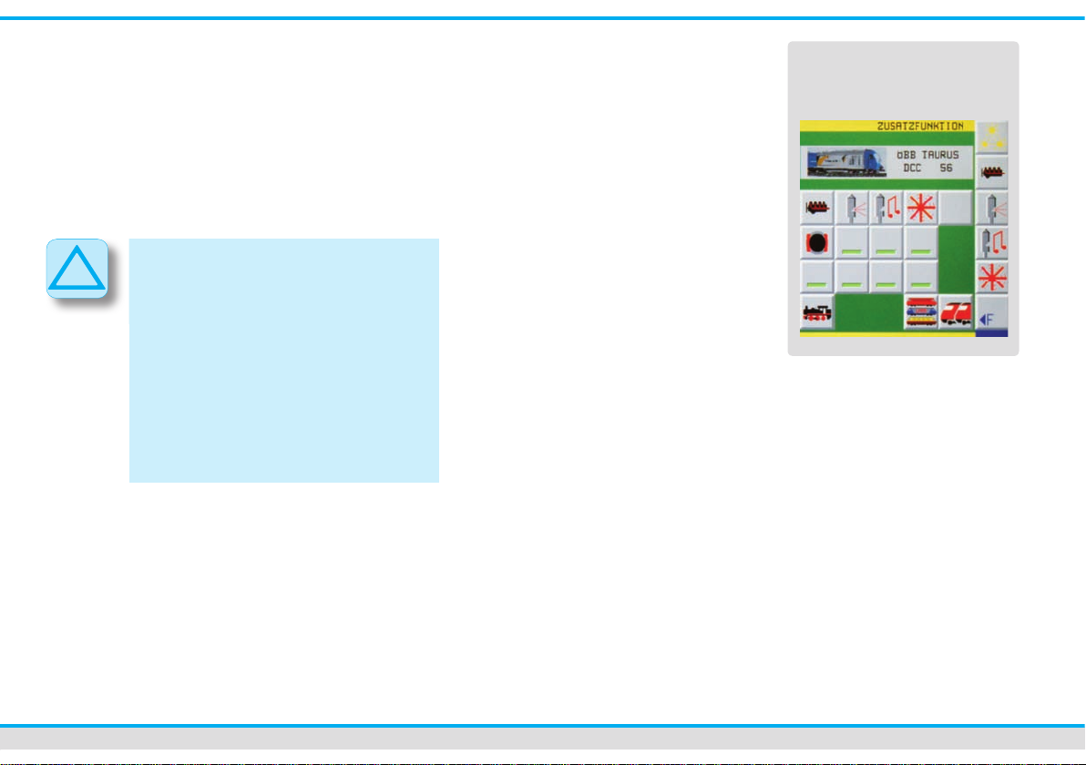
• You switch on or off the additional func-
tions like light, sound etc. by a touch of
the additional function-touch elds.
• Further additional functions are called
up by the touch eld “F►”.
To close the menu “additional functions”
you only have to touch any free place
on the track diagram.
Switching turnouts and signals
The track diagram offers you the most
comfortable possibility of switching turnouts and signals. Therefore you must draw
up the track diagram of your layout rst
(see chapter editors). Alternatively you can
use the direct mode to switch turnouts and
signals.
Switching functional models
on the track diagram:
• Touch the symbol of the functional
model you want to switch with your n-
ger. A choice of different options (turnout positions and signal aspects) will be
displayed on touch elds appearing bet-
ween the two locomotive control panels.
• You switch the turnout or signal directly
by a ngertip on the respective symbol.
The new position is displayed on the
track diagram.
additional functions
of a locomotive
Page 18

18 Quick Start
Switching in the direct mode:
The direct mode of the Commander imitates the keyboard of classic digital command stations. A switching-group consists
of 16 touch elds at the time. In all, you
have 64 groups to your disposal.
• By touching either the eld marked with
“GRP – “ or the eld marked with
“GRP + “ you select the group you want.
Two different switching positions can be
determined for one accessory (e. g. turnout
or signal) by a single touch eld.
• Press shortly once on the respective
touch eld to switch over the
accessory. The illuminated indication
eld shows you the switching status by
changing between red and green.
Assignment of addresses to the
switching elds:
You assign the addresses of the switching
decoders to the respective touch elds of
the track diagram in the turnout- and signal
editor. For further information please refer
to the corresponding chapter on page 23.
Feedback
The Commander can receive feed back information by the s88-Bus or by the Viess-
mann SpeedBus. The Roco Feedback-
Module 10787 can be connected to the
Viessmann LowSpeedBus too.
You should have drawn up the track
diagram of your layout, in order to visualize and to use the feed back in a practical
way. For further information please refer
to the chapter “Track diagram editor” from
page 25 on.
The feed back is also displayed in the
direct mode. In this mode the feed back
information is indicated by red or green
illuminated elds on the left third of the
screen. You select the respective feed
back-module by a touch on the symbol
“MOD - “ or “MOD + “.
From the basic of the feed back information the Commander can carry out many
standard functions and indicate occupied
track sections. Red illuminated elds on
the track diagram show occupied track
sections. Please note that not all eld
types of the track diagram can be illuminated.
Setting up the feed back function:
Press the system-touch eld (left down
below) and then the symbol next to the
label “feedback” in order to call up the
“feedback”-menu.
The set up window opens. A schematic
diagram shows the surface of a
Page 19

19
Viessmann Commander
feedback module (a feedback module
seen from above). Touch the address- eld
and enter the address of the feedback
module. Touch the decoder-symbol and
select a decoder type. The top eld of the
selection list is designated for s88 feedback modules.
You can see the schematic diagram of
your selected decoder at the top edge and
the edge down below. Touch slightly the
decoder input you want. The respective
input will be illuminated in red. Assign now
the corresponding elds on the track dia-
gram to the activated input.
Assign track diagram elds:
• Press the touch eld
“fade out feedback decoder”.
• Touch the elds of the track diagram
you want to be indicated as occupied
track section by illumination in colour,
one after the other. The progress-bar
at the top in the middle of the picture
gures the enumeration of selected
elds.
• You can annul your last inputs with the
arrow key showing to the left, in case
that any input error occurred.
• Delete the respective elds by pressing
the “delete”-key.
• You can simulate the feedback with the
two switching elds on the right of the
counter bar.
• To nish, you press the key “fade in
feedback decoder”. The Commander
saves the entered elds and shows the
feedback menu again. Now, you can
assign the corresponding elds to the
next input of the feedback module.
• When all feedback sections are assi-
gned to the corresponding feedback
module inputs, don’t forget to save the
entered sections de nitely by pressing
the key “Save”.
• In order to close the menu, touch the
“Exit”-key in the bottom right-hand
corner.
Fade out feedback decoder Fade in feedback decoder
counter bar
annul
delete
Page 20

20 Quick Start
Editors
The Commander offers several different
editors in order to visualize your layout and
to control the locomotives.
Locomotive editor
You can enter and change the locomotives’
data with this editor. You can modify a data
record at any time. Select the respective
locomotive and hand her over to a control
panel.
• Touch the speedometer of the control
panel with your nger or an electronic
pen until the locomotive window opens
(approx. 1-2 seconds).
• Carry out the desired modi cations and
save them as well in the locomotive decoder as in the locomotives’ data record
of the Commander.
The menu consists of several index cards
you can choose to edit them:
1. locomotive icon, address,
text eld for remarks
2. additional functions
3. locomotive driving behaviour
4. decoder setup
5. speed step ramp
6. programming the CV
(variable coef cient)
7. speed step preselection
8. editing of the locomotive list
• Touch the different setting keys (e. g.
address, name etc.) in order to make
the adjustment.
• You have either elds with numbers or
elds with letters, elds to click on or
slide controls to your disposal to enter
the data, in dependence on the context.
• Con rm the input you made by the
number-or character- elds with “OK”.
• Register the CV-data for each CV apart
in the locomotive decoder.
Page 21

21
Viessmann Commander
i
Märklin-Motorola-Decoder:
The address of older locomotive decoder with the Märklin-Motorola format is
adjusted by Dual Inline switches (DIPswitches). The Commander shows you
graphically how to adjust the switches
for the respective address, in the
Märklin-Motorola-protocol.
• Press the key “Save” in order to save
the complete new data-record of the
locomotive and to charge it in the locomotive-data record of the Commander.
• Don’t forget to register the adjusted
data in the locomotive decoder too.
• You close the menu by a touch on the
“Exit”-key in the bottom right-hand
corner.
Touch elds:
Read selected data of the
locomotive decoder
Transmit selected data to
the locomotive decoder
Entering-mode of a text
Entering-mode of numbers
and special characters
Delete entry
Finish, con rm input
Save complete data record
in the Commander
Exit menu
Remark on the additional
functions:
You have different additional functions to
your disposal, as light, sound, movement
etc, depending on the locomotive model or
the decoder type. The ve priority-function
keys are always displayed and thus immediately accessible.
All other additional functions are selected
by the “F►” touch eld.
You can edit the additional functions with
the index card 2 of the locomotive editor.
The index card has three sections. On the
left you see a list of all possible additional functions. With the navigator you scroll
through the list.
All available function keys are listed in the
middle part.
The ve priority-function keys that are al-
ways displayed on the control panel in
order to have an immediate access are
shown on the right hand side.
OK
ABC
123
CL
Page 22

22 Quick Start
• Touch the respective function-key
(F01 – F12). It begins to twinkle. With
the navigator you scroll through the list
of the additional-function-symbols.
• Press the symbol you want and it will be
transferred to the selected function key.
How to edit the priority function keys
(VT1 – VT5):
• Touch the respective function-key
(F01 – F12). It begins to twinkle.
• After that, press the priority-function key
you want. The symbol will be transferred
to this selected priority-function key.
the correct value of the CV.
Please refer to the operating instruction
of the decoder.
Remark on the speed step ramp:
You can easily dene a separate speed
for each speed step with the graphical
speed step ramp. The Commander offers
you symbols of three already predened
ramps. You can activate them by a tip on
the wished symbol. Alternative you can
adjust the speed individually. Keep your
nger or the electronic pen pressed on the
respective speed step-bar and pull it to the
speed you want.
Remark on the driving behaviour
and the decoder setup:
The inputs for the driving behaviour of the
locomotive are done on the index cards 3
and 4. There you can modify the values
from the CV’s 2 to 8 and 28 / 29.
Please, be mindful to read the locomotive decoder CV values 2 to 8 for each CV
apart and to save it again onto the decoder
in case of a modication. You can change the values by a tip on the respective
number and by moving the slide control.
The values of the CV’s 28 and 29 can be
entered as a number directly. Alternative
you can touch the listed options.
The Commander calculates automatically
Remark on the CV-programming:
You can select the CVs individually and
edit them bit by bit or as a decimal value.
Please execute modications only if you
have acquainted yourself with the subject.
This way you avoid programming incorrect
data to the decoder as that could be the
cause of malfunctions.
Remark on the preselection
of speed steps:
You can dene three speed levels with
different speeds for each locomotive: low
speed, average speed and cruising speed.
These values can be used for the
assignment of individual speeds to each
locomotive when programming a route.
Page 23

23
Viessmann Commander
i
Programming of the speed regulation:
• Touch slightly the respective speed
symbol (see symbols on page 29).
• Regulate the speed by one of the
speed control knobs.
• Con rm the adjusted speed value by
pushing the key “Set”.
Remark to locomotive-lists:
You can organize your locomotives’ list
with the index card “edit the locomotive
list”. Assign your locomotives to the
different sub-lists and de ne the position
where the locomotive should be listed in
the respective list.
Organize the locomotive list:
• You select a locomotive out of one of
the lists with the navigator. Her background will change to red.
• Push on the ash pointing to “parked
locomotive” in order to park the
locomotive.
• Select the new position of the locomoti-
ve in one of the lists with the navigator.
Attention: the parked locomotive will be
inserted in the list just above the
selected locomotive position.
• Add the locomotive to the respective list
by pushing the ash pointing to
“Locomotive list”.
Turnout- and signal editor
Turnouts and signals can be connected
to the track power of the Commander
(main track output) or to the new Viess-
mann LowSpeedBus output. But you need
special decoders for a connection to the
LowSpeedBus.
How to edit decoders:
You can program decoders either in the
“track diagram-mode” or in the
“direct-mode”.
• Activate the menu “turnout –and si-
gnal editor” by pressing the system-
touch eld (left down below).
• Push slightly on the respective symbols
next to the label “Turnout/ Signal” in
order to open the editor.
Tip:
You can also call up the menu
“turnout- and signal editor” if you are in
the track diagram-mode. Simply press
the respective turnout- or signal symbol
on the track diagram for approx.
1 – 2 seconds. This presupposes that
you have drawn the track diagram rst.
The con guration of the switches and
signals can be done directly from the
diagram then.
Turnout- and signal editor
Page 24

24 Quick Start
i
The following adjustment options are at
your disposal:
Symbol-Type: The Commander shows
you the respective symbol of the track
diagram.
Address: Touch slightly the address eld
and enter a standard address-value by the
keyboard on the touch screen (Please
refer to the operating instruction of the
decoder). You can delete your input with
“CL” and con rm it with “OK”.
Adjusting the outputs of the decoder:
You can reverse the outputs of an incorrect
connected switch motor so it acts
reversed.
Indication: You can adapt the representation of the turnout to the track diagram.:
Turnout driving unit: You can choose
between a conventional solenoid-drive and
a servo drive. The selected drive unit type
can be con gured individually now,
depending on your choice.
On the next page of the menu you adjust
the format of the digital system and you
determine if the decoder executes a
particular switching command every
time the system starts.
• Enter the wished adjustments.
• To nish, touch the key “Save” in order
to save the complete data record of the
respective accessory on the
Commander.
• You close the menu by pushing “Exit”.
You can modify your adjustments at
any time by calling up the menu again.
Connection to the track power:
Connect the decoders (accessories with
solenoid drive and signal-decoder) to the
red and brown connections of the track
power according to the decoder operating
instruction. Carry out the decoder
programming procedure according to the
operating instruction..
DCC-decoder:
Activate the programming mode of the
decoder. Touch the respective touch
eld of the track diagram and operate
the switch. The Commander transmits a
control command to the corresponding
address. The decoder saves the received address as its own.
Alternative you can directly enter a control command to the chosen address in
the “direct mode”, on condition that the
decoder is in the programming mode.
Most of the decoder con rm the trans-
mission of the address by the execution
Page 25

25
Viessmann Commander
i
!
of an operation and return to the normal
running mode after that. Please respect
absolutely the operating instruction of
the decoder.
Märklin/Motorola- Decoder:
The address of older locomotive decoder with the Märklin-Motorola format is
adjusted by Dual Inline switches (DIPswitches).
The Commander shows you
graphically how to adjust the switches
for the respective address, using the
Märklin-Motorola-protocol.
Connection to the
Viessmann-SpeedBus:
Connect an appropriate decoder to the
LowSpeedBus of the Commander.
The Commander identi es the decoder.
A “Selection-window” pops up and the
Commander makes it possible for you to
de ne the position of the new accessory in
the track diagram and to con gure it.
Track diagram editor:
The track diagram enables you to draw
or modify track diagrams directly with the
Commander. You can draw up and save
three different track diagrams. The track
diagram can be larger than the displayed
section on the Commander.
Track diagrams can only be edited when
the Commander is in the mode “manual
operation”. The touch eld in the bottom
right-hand corner must represent a red
signal (symbol of the signal aspect Hp0
or Hp0/Sh1).
Page 26

26 Quick Start
How to edit track diagrams:
• Select the desired track diagram.
• Activate the menu “track diagram
editor” by pressing the system-touch
eld (left down below).
• In order to open the editor push slightly
on the respective symbol next to the
label “Track diagram”.
You are now in the track diagram editor
and you can see the raster eld of the
chosen track diagram just in the middle.
On the left you see an arrangement of
touch elds representing different catego-
ries of symbol eld types (Track symbols,
turnout symbols, signal symbols etc.).
You select the respective category.
The elds belonging to this category are
displayed at the top. On the left is a selec-
tion list where the just active eld type will
be pointed out by an enlargement and indicates you the item-no of the track-symbol.
On the right you have touch elds in order
to administrate the track diagram:
Save track diagram (saves
the actual conguration of
the track diagram)
Editing track diagrams is very easy:
• Select the desired eld type out of the
different categories of symbol eld
types. The respective symbol is
displayed on the selection list and at
the same time on the actual position of
the cursor on the track diagram-area.
• Drag it to the nal position with your
nger or an electronic pen.
• Turn the symbol as long as it points to
the right direction with the speed-knob.
• Press now the navigator or speed knob
until you hear a click, in order to x the
symbol in the track diagram.
This way you can draw eld by eld the
whole track diagram.
• By pressing the “Save”-symbol you
save the track diagram.
• After that you leave the track diagram
editor by touching the key “Exit”.
Delete track diagram (cancels the whole diagram)
Load track diagram (loads
down the last saved conguration of the diagram)
Page 27

27
Viessmann Commander
Route editor
The control of routes is an important tool
to automate the operations on your layout.
You can call up and exploit routes automatically either time controlled or by feedback modules, or manually at the touch of
a button. The Commander visualizes
switched routes by a yellow illumination.
How to set up and edit a route:
You have to design the track diagram
before setting up a route.
So, draw the track diagram of your layout
with the Commander rst.
• Call up the menu “Route” by pressing
the system-touch eld
(left down below).
• Push slightly on the respective sym-
bol next to the label “Route” in order to
open the editor. You are now in the
route editor. You can program all
parameters of a route using the 9 index
cards you have to your disposal.
On the left and right hand side of the index
cards are several different touch elds in
order to edit the inputs.
previous index card
next index card
save complete route on the
Commander
load complete route
delete selected index
card entry
Page 28

28 Quick Start
exit menu
Call up the relevant track
diagram to select track
sections. Interconnection
of different track diagrams
in order to dene starting
point and destination
is possible.
Show again the menu of
the index card.
Go through the index cards one after
another and make the respective entries in
order to set up and to edit a route.
Index card 1 and 2:
• Enter the route number and the
explanatory comment using the alphanumeric screen keyboard.
• Select the operating mode
(automatic or manual operation)
• Dene the starting point and the
destination on the track diagram (optional). Touch one of the index card-selec-
tion elds (previous or next index card).
After that a track diagram opens up.
• Choose the appropriate track diagram.
• Touch the respective symbol eld you
want. The chosen symbol eld shows a
green twinkling frame.
• Return to the index card.
Index card 3:
You can call up a route either by feedback
modules or time controlled. In order to do
that, press the desired touch eld. On the
track diagram you select the feedback
modules you take into consideration for an
automatic call up of the route.
In case that a passing train activates the
respective feedback module the Comman-
der can automatically switch over and
open the proximate route, if it is not
occupied. Using intelligent feedback
modules the route control can also be
activated in dependence of a special train.
Index card 4:
Enter all feedback sections belonging to
a route into the index card “respect feedback”. This way you ensure that a route is
only switched and unlocked, if the
respective sections are really free.
Index card 5:
You enter all commands that are necessary for the operations on the route in the
index card “control commands”. This includes the switching of turnouts and signals
belonging to the route but also the driving
behaviour of the train.
You select the turnouts and signals in the
track diagram. Touch the respective
Page 29

29
Viessmann Commander
accessory symbol and adjust the position
with the corresponding key on the
switching touch elds (e. g. straight ahead
or diverging route, signal aspect “stop” or
“proceed”).
After that return to the index card.
The programmed control commands of this
locomotive are valid for all locomotives.
In case that you want to dene them for
a special locomotive, select a locomotive
icon out of the list of locomotives as
follows:
Touch the explanatory comment area
associated to a control command (e.g. 03
no command) in order to pick out a locomotive. After that, you select the locomo-
tive symbol-eld out of the touch elds on
the right hand side. A list of touch elds
opens up and you can adjust direction and
speed of a train with the appropriate key.
Stop
low speed
average speed
high speed
forward movement
backward movement
keep sense of driving
Inverse sense of driving
(e.g. for shuttle trains)
Touch the locomotive symbol-eld out of
the row of command touch elds. Select a
locomotive out of the list then. This way the
programmed route and speed adjustments
are only valid for this specic locomotive.
By entering different locomotives you
can dene for each train an individual
route and running speed .
index card 6:
You can assign “switching-track”-functions
to specic feedback sections by the
index card 6.
The Commander carries out a specic
function, like the activation of a sound or
the switching of headlights when a
locomotive reaches the respective
feedback section.
index card 7:
Dene at least one feedback section as
destination contact. Touch the selection
eld of the index card. A track diagram
opens up. Select the appropriate track
diagram. If you touch the respective sym-
bol eld on the track diagram, it shows
now a green twinkling frame.
Page 30

30 Quick Start
Switch back to the index card.
index card 8:
This index card is intended for the
cancellation commands of a route.
After the train has passed the route, you
can cancel her and open the track sections
for the next train.
The elements the route is composed of
(turnouts and signals) have to be switched
back to their initial position. Refer to the
procedure described in the index card 5.
index card 9:
By this index card you set up the route
locking (ank protection).
For reasons of safety different routes can
not be switched at the same time (e. g. exit
tracks running parallel in the station and
leading to the same main track).
The Commander denes automatically
which routes should be locked in case that
they explore the same feedback modules.
In case of conicting routes not using the
same feedback modules you can program
the reciprocal interlocking manually.
• When the entries are done in all index
cards, save the route and close the editor by pushing the “Exit”-key.
You can call up again the route by entering the route number in the route editor
and modify the inputs.
Page 31

31
Viessmann Commander
System set-up
In the system setup-menu you dene
specic system parameters, normally only
once. Touch the system-menu touch eld
(left down below) and select the respective
parameters in order to adjust them.
Language
Determine the language by the
ag-symbol..
format of the NMRA-DCC system. A hybrid
exploitation of both protocols is possible.
Model-time
The Commander can accelerate the
sequence of time in contrast to the realtime in order to make the operations on
your layout more realistic. You can adjust
the accelerating factor from 1,0 (real-time)
to 10 (model-time) innitely variable with
the slide control.
Display-brightness
The slide control enables you to adjust the
display-brightness innitely variable.
Starting mode
Select one of the three modes: automatic
control, semi automatic control or manual control. The Commander boots up in the
respective starting mode.
Protocols
Choose the data format. The Commander
is designed for the Märklin-Motorola data
format old and new as well as for the data
Software-update
We are always bringing the software of the
Commander up to date. Please take a look
at our special Commander-Homepage
www.viessmann-commander.de
from time to time, to see if there are any
updates of your software version.
The update can be downloaded and
installed on the Commander afterwards.
We would be glad to inform you of new
software packages with extended operational features. So, please register your
Commander right now at Viessmann!
Respect in any case the instructions for
the update-software.
Page 32

32 Quick Start
!
!
i
Information:
You need a PC equipped with the
windows system and USB 2.0
connection jacks for the update.
Attention:
Switch of all energy saving options!
Your computer de nitely should not
switch over to the standby mode or to
the state of rest. This can especially
occur to laptops. Adjust the energy
saving options by windows before
executing the update.
How to update the Commander:
The software update can easily be
installed on the Commander by yourself.
• Connect the switched on Commander to
the PC by an USB-cable.
• Install the driver for the USB-interface at
the rst interconnection of Commander
and PC.
You will nd the driver on the DVD.
• Press the system-menu touch eld (left
down below) in order to open the
“system-parameter”-menu.
• You activate the software mode at a
slight touch on the respective symbol
next to the label “software update”.
The Commander is now in the software
update mode.
• Please respect the information
of the Commander.
• To start up the update software double-
click on your PC.
• Follow the instruction of the update
software on your PC.
Attention:
As the update of the Commander can
take up to 20 minutes, please don’t get
impatient.
Never cut off the power supply of the
Commander during the update procedure! In consequence of an incomplete
update the Commander may not boot
up any more. Sending in the
Commander to the Viessmann
after-sales-service is unavoidable then
and at the owner‘s expense startet.
Page 33

33
Viessmann Commander
Information
Conformity declaration
Technical specications
Commander:
Dimensions: 268 mm x 64 mm x 180 mm
Weight: 1,1 kg (only Commander)
Operating voltage: 18 V =
Booster-Output: 3,0 A
Programming-track Output: 1,2 A
Display: TFT-Display, 800 x 480 Pixel
Ambient temperature:
5 – 35° C (operation)
-10 – 45° C (storage)
Protocols: Märklin-Motorola old / new,
NMRA-DCC
Power supply:
A power supply with the technical speci-
cations listed down below is included in
the content of delivery. For the electricity
supply of the Commander use exclusively
this power supply.
Dimensions: 150 mm x 75 mm x 40 mm
Input voltage: 110 – 230 V~
Input frequency: 47 – 63 Hz
Output voltage: 18 V=
Output current: 5,5 A
We, Viessmann Modellspielwaren
GmbH, Am Bahnhof 1, D-35116 Hatzfeld,
declare in our exclusive responsibility that
the product,
Viessmann Commander,
this declaration relates to, is built in conformity with the following technical standards:
EN 55014-1:2002-09, EN
55014-2:2002-08, EN 61000-3-2: 1995,
EN 60742: 1995, EN 61558-2-7: 1998
As agreed with the guidelines:
89 / 366 / EWG
and 73 / 23 / EWG.
The Commander carries the CE-sign.
Pollution control / disposal
Waste disposal of old electrical and electronic devices by a waste separation
system in compliance with the European
Union and other European countries.
The disposal of products marked with a
crossed out dustbin together with the
normal rubbish is not allowed. At the end
of her life they must be handed in to a
collecting point for the recycling of
electrical and electronic devices.
Page 34

The above mentioned symbol on the
product, the operating instruction or the
packaging points it out. The raw materials
can be recycled, according to their
designation.
By reuse, exploitation of the raw material and other forms of recycling old devices,
you contribute considerably to the
pollution control.
turer cannot be held responsible for any
damage and consequential damage resulting from the improper use of this product (non-compliance with the operating
instruction, misuse, improper handling,
overload, usurpation, structural modications on your own authority, use of force,
reaction on humidity, superheating or something). Liability in such case rests with
the user.
Ask your local government for information
about the appropriate waste disposal
department.
Warranty information
All functions of every component are checked over before delivery. There is a twoyear warranty for the component from the
date of purchase onwards. In case that any
malfunction occurs during that time, please
contact Viessmann immediately. If a test
shows that the source of trouble is a production-or material defect, the component
will be repaired free of charge. Excluded
from the guarantee are defects of the component resulting from incorrect use. Excluded from the guarantee are all defects of
the component resulting from non-compliance with the operating instruction, misuse, improper handling, overload, usurpa-
tion, structural modications, use of force,
superheating or something. The manufac-
34 Quick Start
Further informations
For detailed information about the use of
the Commander, please look at the included Learning-DVD.
You can play it on any commercial DVDplayer or on your PC. The DVD contains
a multimedia instruction. The operation of
the Commander is explained step by step
by short video lms. Additionally the DVD
includes this short operating instruction
as PDF-document and software programs
(computer programs) for the Commander.
Please take a look at our special
Commander-Homepage:
www.viessmann-commander.de
We wish you much fun and success with
the Commander now!
Page 35

Zoom factor
Editors
Displaying modes
Operation mode
Overall view 60%
Detail 125%
Normal 100%
Overall view 75%
Locomotive
Turnout / Signal
Feedback
Routes
Track diagram
System parameters
Semi automatic
Fully automatic
Manual operation
Stop operation
Locomotives
Loco & track diagr.
Track diagram
Direct mode
Track diagram 1
Track diagram 2
Track diagram 3
Locomotive editor
Switching decoders
feedback editor
Route editor
Track diagram editor
Protocols
Starting mode
Software update
Display
Input / Output
# of s88-modules
# Roco-feedback
Decoder (LSB)
Feedback (LSB)
Handhelds
Model-time
Language
Overview of the menu structure
Viessmann Commander
Page 36

Overview of the touch elds
Zoom-menu
System-menu / editors
Display mode-menu
Mode „locomotive and track diagram“
Modus „locomotives“
Modus „track diagram“
Direct Mode
Operating mode „fully automatic“
Operating mode „semi automatic“
Operating mode „manual“
previous index card
next index card
load
save
delete
read data of the loco-decoder (CV-values)
write data into the loco-decoder (CV-values)
Editor: locomotives
Editor: turnout and signal
Editor: feedback
Operating mode „stop operation“
Exit menu
Editor: route
Editor: track diagram
Page 37

© 2007 Viessmann Modellspielwaren GmbH
All rights reserved. Errors and omissions excepted, subject to alteration due to technical improvements and rights
to alteration of terms of delivery without notice reserved. All electrical information and mechanical measure indications without warranty. Excluded from the guarantee are defects resulting from incorrect use.
The manufacturer cannot be held responsible for any damage and consequential damage resulting from the improper use of this product as e.g. non-compliance with the operating instruction, improper handling, structural mo-
difi cations on your own authority etc.. Liability in such case rests with the user. Not suitable for children under 14
years. Risk of injury can result from improper use.
Märklin is a registered trade mark of Gebr. Märklin & Cie GmbH, Göppingen (Germany). RailCom is a registered
trade mark of Lenz Elektronik GmbH, Gießen (Germany). All other trade marks are ownership of the respective
owner of the legal rights.
Any copy or reproduction of this documentation is only allowed on the prior written authority of Viessmann.
5300
Commander
Quick Start
SachNr.: 92373
Stand: 01/2008 Ko
Viessmann
Modellspielwaren GmbH
Am Bahnhof 1
D – 35116 Hatzfeld (Eder)
 Loading...