

Page 1
Technical Data Manual
Model Nos. and pricing: see Price List
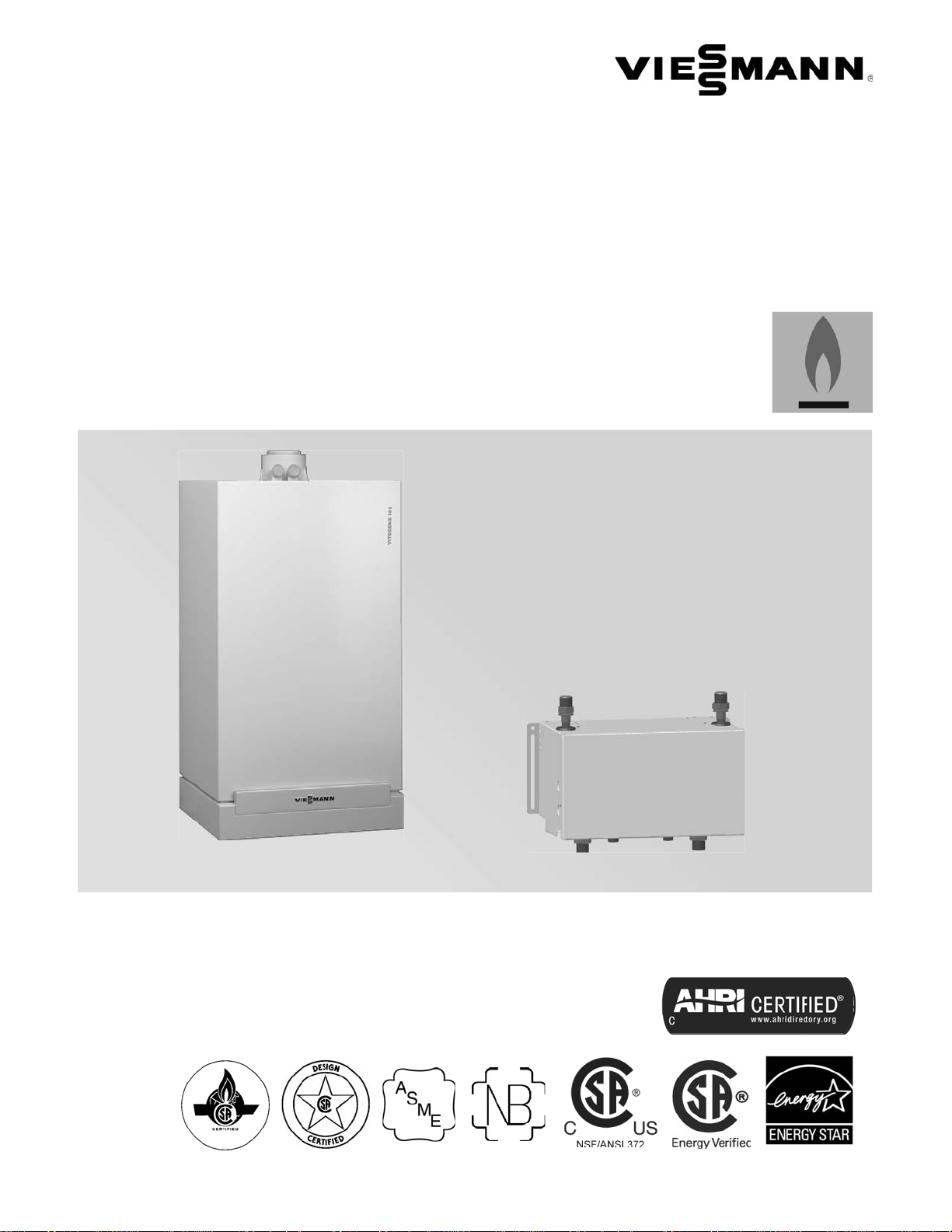
Vitodens 100-W
WB1B Series
Wall-Mounted, gas-fired condensing boiler
with optional on demand hot water CombiPLUS Kit
Heating input: 37 to 118 MBH
10.8 to 34.5 kW
VITODENS 100-W
Vitodens 100-W, WB1B
(with pre-installed coaxial vent pipe adaptor)
Gas-Fired Wall-Mounted Condensing Boiler with modulating
stainless steel MatriX cylinder burner, stainless steel InoxRadial heat exchanger for room air independent operation
(using a direct vent system) or room air dependent operation.
Optional CombiPLUS Kit providing reliable on demand hot
water without a DHW tank is available.
H
5601 189 - 01 03/2014
CombiPLUS Kit
Page 2

General
Product Information
Vitodens 100-W, WB1B Technical Data
Equipped with a Viessmann stainless steel heat exchanger
for lasting performance and reliability and a modulating
MatriX cylinder gas burner, the Vitodens 100-W wallmounted condensing boiler is the perfect combination of
value, quality and Viessmann technology.
The benefits at a glance:
Outstanding efficiency
of 94.0 % A.F.U.E. on all models.
Lasting performance
with Viessmann-made SA240 316Ti stainless steel
Inox-Radial heat exchanger constructed to ASME
Section IV and CSA B51.
Low-emission
with fully-modulating stainless steel MatriX cylinder
burner. Factory calibration eliminates adjustments in
the field.
< 29 ppm NOx (at 3% O2)
< 40 ppm CO (at 3% O2)
Control variety
Integrated boiler control interfaces with any level of
external control - from room thermostat to outdoor
reset and more.
Compact, lightweight wall mount design
and zero clearance to combustibles make it a great
choice for limited-space installations.
Extremely quiet operation
quieter than most refrigerators.
< 50 dBA [at 3.3 ft. (1 meter)]
Multiple venting options
- Horizontal or vertical sealed combustion
coaxial, PP(s) vent system (Viessmann supplied).
- Horizontal, vertical or hybrid sealed combustion
double-pipe CPVC vent system (field supplied).
- Horizontal or vertical single pipe CPVC vent system
(field supplied).
- Horizontal or vertical single or double pipe PP(s),
flexible vent system (Viessmann supplied).
Suitable for high altitude levels
of up to 10,000 ft. (3,000 m) without deration.
Built-in automatic frost protection
allows boiler to be shut off for an extended period
of time while protecting it against freeze-up.
Reliable on demand hot water
with an optional CombiPLUS kit (no DHW tank required).
- Plate type heat exchanger
- Built-in diverting valve
- Built-in Grundfos 3-speed pump
- Built-in pressure bypass valve
- Built-in water hammer arrester
- Built-in flow sensor
- Built-in temperature sensor
- Supplied with a pressure relief valve rated at 150 psi
Note: Check the boiler rating plate on the Vitodens 100-W,
models WB1B-26 or WB1B-35 to ensure it states
compatibility with the CombiPLUS kit.
Limited lifetime warranty
in residential applications.
Easy installation, service and maintenance
with all pipe connections located at the bottom
and serviceable components (including electrical
connections) easily accessible from the front.
2
Certified to CSA Low Lead Content Certification Program;
including US Safe Drinking Water Act, NSF/ANSI 372
as well as other applicable US State requirements.
5601 189 - 01
Page 3
Vitodens 100-W, WB1B Technical Data
Product Information
General
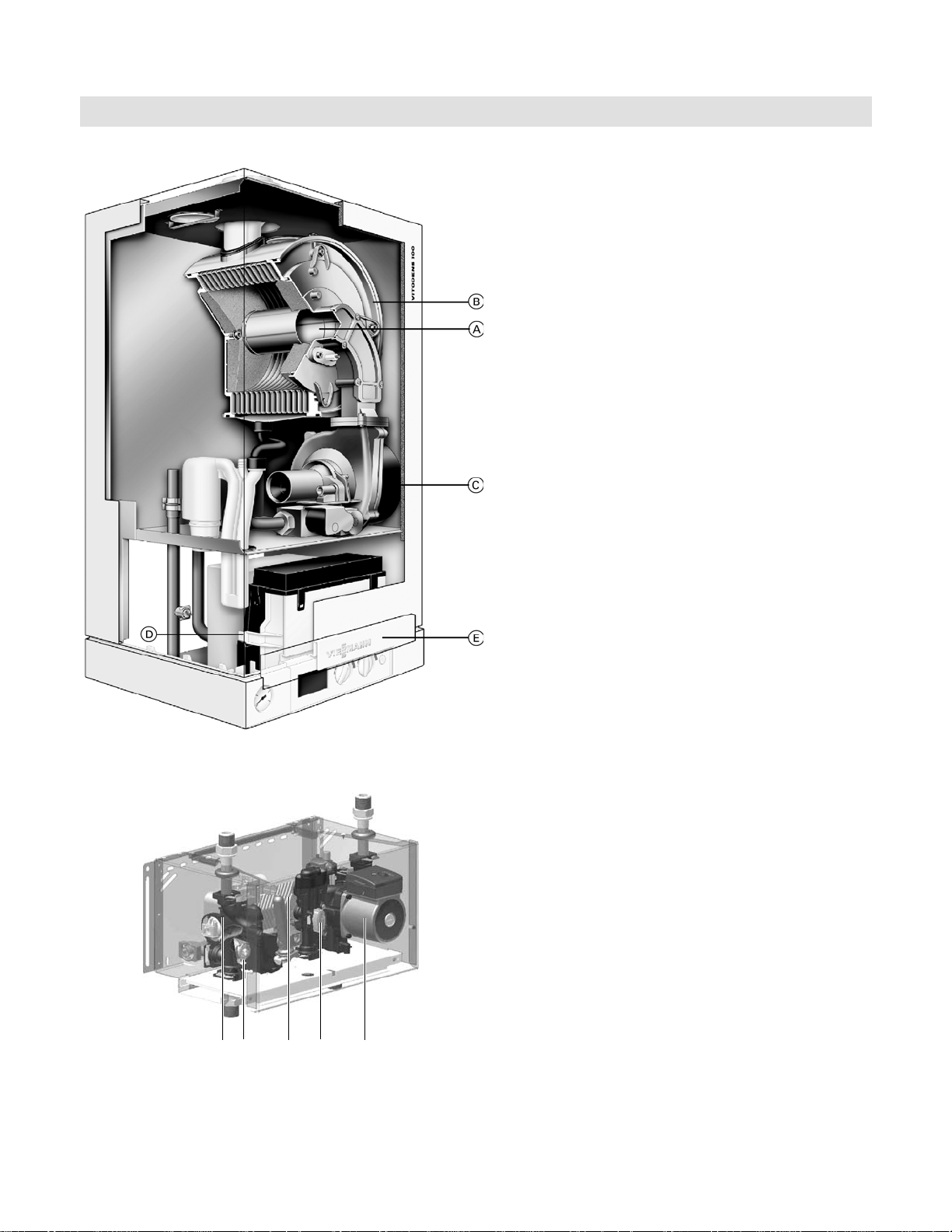
Boiler cross-section
Legend
A Stainless steel MatriX cylinder burner
B Inox-Radial stainless steel heat exchanger
C Burner blower
D Gas and hydronic connections
E Boiler control
Standard Equipment:
Wall-mount boiler and installation fittings c/w 30 psi
pressure relief valve, pressure gage, gas shut-off valve,
two fill/drain valves, all mounting hardware, outdoor
temperature sensor, and LP conversion kit.
H
JI
Note: Products may not look exactly as illustrated.
5601 189 - 01
GF
CombiPLUS cross-section
Legend
F Plate-type heat exchanger
G Boiler / DHW pump
H Flow sensor
I Pressure by-pass valve
J Diverting valve
3
Page 4

Technical Data
Vitodens 100-W, WB1B Technical Data
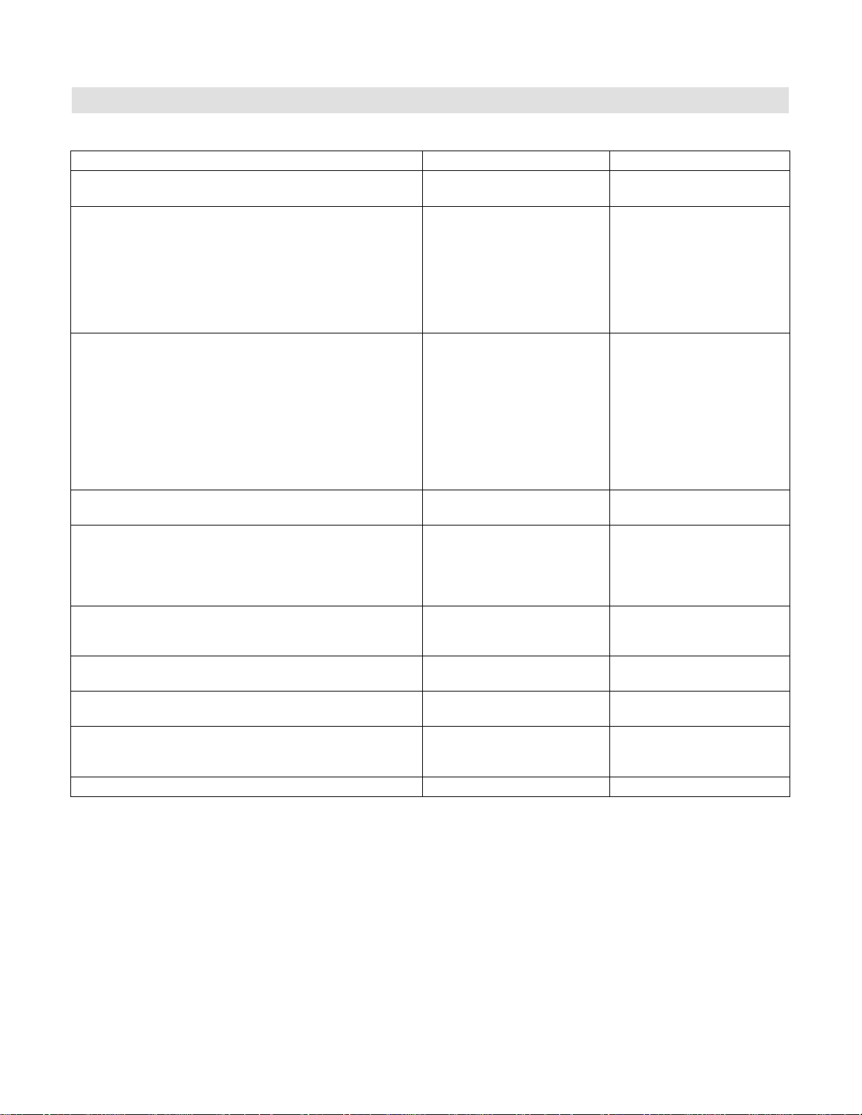
Specifications
Standard heating boiler
Boiler Model No. WB1B 26 WB1B 35
Natural gas and LPG
CSA input
CSA output/DOE
1
heating capacity
Net I=B=R rating 2
Heat exchanger surface area
Min. gas supply pressure
Natural gas
LPG
Max. gas supply pressure
3
Natural gas and LPG “w.c. 14 14
A.F.U.E. % 94.0 94.0
Weight
Shipping weight
Boiler water content
Boiler max. flow rate
4
USG
Max. operating pressure
(max. allowable working pressure)
at 210º F (99º C)
Boiler water temperature
- Adjustable high limit (AHL) range
- space heating (steady state)
- DHW production (set-point)
MBH
kW
MBH
kW
MBH
ft.
m
“w.c.
“w.c.
lbs
kg
lbs
kg
GPM
L/hr.
psig
bar
ºF (ºC)
ºF (ºC)
37-91
10.8-26.7
34-83
9.9-24.3
37-118
10.8-34.6
34-108
9.9-31.6
72
2
2
10.23
0.95
10.23
0.95
4
10
78
34.1
34.1
95
43
0.87
L
3.3
0.87
6.2
1400
1400
45
3
86 to 176 (30 to 80)
176 (80)
94
4
10
78
95
43
3.3
6.2
45
3
- Fixed high limit (FHL)
Boiler connections
Boiler heating supply and return
Pressure relief valve
Drain valve
NPTM (male) “
NPTF (female) “
(male thread) “
ºF (ºC)
Dimensions
Overall depth
inches
mm
Overall width
inches
15 c
mm
Overall height
inches
28 b
mm
1
Output based on 140º F (60º C), 120º F (49º C) system supply / return temperature.
2
Net I=B=R rating based on piping and pick-up allowance of 1.15.
3
If the gas supply pressure exceeds the maximum gas supply pressure value,
a separate gas pressure regulator must be installed upstream of the heating system.
4
See “System Flow Rates” on pages 20 to 25 in this manual.
4
210 (99)
c“
c“
c“
14d
360
400
725
c“
c“
c“
14d
360
15 c
400
28b
725
5601 189 - 01
Page 5
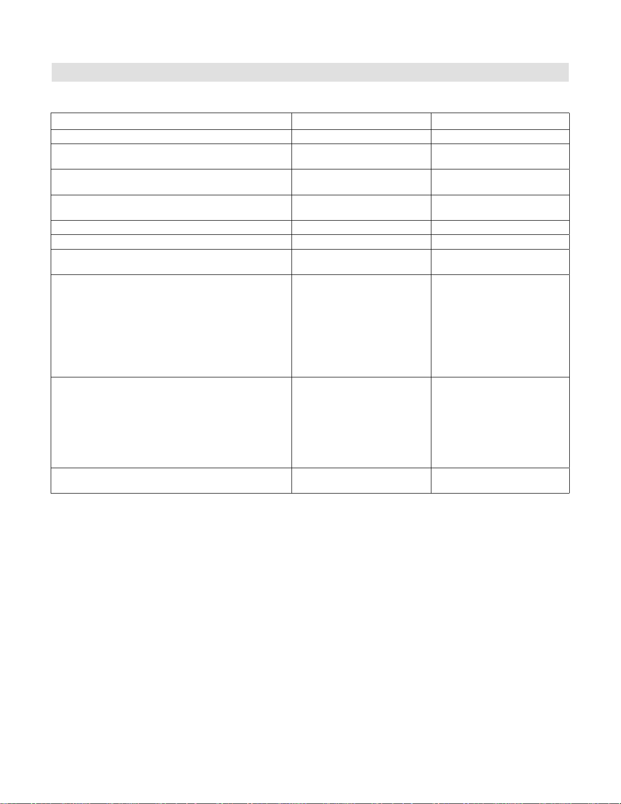
Vitodens 100-W, WB1B Technical Data
Specifications (continued)
Technical Data
Standard heating boiler
(continued)
Boiler Model No. WB1B 26 WB1B 35
Gas supply connection
Flue gas
5
NPTF
(female)”
cc
Temperature at boiler
return temperature of
86º F (30º C)
- at rated full load
- at rated partial load
ºF (ºC)
ºF (ºC)
127 (53)
90 (32)
131 (55)
90 (32)
Temperature at boiler
return temperature of 140º F (60º C)
ºF (ºC)
167 (75)
172 (78)
Flue gas value
Mass flow rate (of flue gas)
- at rated full load
- at rated partial load
Available draught
lbs/h
kg/h
lbs/h
kg/h
Pa
mbar
79.2
36.0
33.0
15.0
100
1.0
100.1
45.5
33.0
15.0
100
Flue gas temperature
sensor limit ºF (ºC) 230 (110) 230 (110)
Average condensate
flow rate
6
with natural gas
- TS/TR =122 / 86º F (50 / 30º C) USG/day
L/day
Condensate
connection
7
hose
nozzle
1.95-2.3
8-9
2.5-2.8
9.4-10.5
Ø in 1 1
Boiler flue gas
connection
8
Combustion air supply coaxial
connection
8 single
outer Ø in (mm) 4 (100)
Ø
in (mm) 2e (60) 2e (60)
4 (100)
2e (60)
2e (60)
Noise level (at 1 meter)
- at full load
- at partial load
High altitude (factory set)
9
(dB)
(dB)
47
40
ft. (m) 0-5,000 (0-1,500) 0-5,000 (0-1,500)
1.0
49
42
5
Measured flue gas temperature with a combustion air temperature of 68° F (20° C).
6
Based on typical boiler cycles, including partial load conditions.
7
Requires 1”(25) mm tubing. See Vitodens 100-W Installation Instructions for details.
8
For detailed information refer to the Vitodens Venting System Installation Instructions.
9
For 5,000 to 10,000 ft. (1,500 to 3,048 m) operation, a control programming change is required.
Refer to the Installation and Service Instructions for details.
For information regarding other Viessmann System Technology componentry,
please reference documentation of respective product.
5601 189 - 01
5
Page 6
Technical Data
Vitodens 100-W, WB1B Technical Data
Specifications (continued)
CombiPLUS (Integrated with the Boiler)
Boiler Model No. WB1B 26 WB1B 35
DHW supply temperature ºF (ºC) 140 (60) 140 (60)
Continuous draw rate
with DCW temp. of 56º F (13º C)
Continuous draw rate
at t= 63º F (35K)
Maximum allowable working
pressure (potable water) psi 150 150
Test pressure psi 300 300
Connections, DHW and DCW NPTM (male) “
Connections to boiler supply/return
and to heating supply/return
Dimensions
Overall depth
Overall width
Overall height
Height with pipe connector
Integrated pump flow rate
DHW production @ 23 ft. (9.8 m)
Head pressure
Heating system operation
with system side additional
drop in pressure of max. 6 ft. of
water (1.8 m)
Weight lbs
1
2
NPTM (male) “
USG/h
L/h
USG/h
L/h
inches
mm
inches
mm
inches
mm
inches
mm
USG/min.
L/h
USG/min.
L/h
kg
99
374
156
589
b“ b“
c“ c“
9.8
250
17
432
8.7
223
13
331
5.63
1278
6.2
1408
25
11
5.63
1278
1408
147
556
216
800
9.8
250
17
432
8.7
223
13
331
6.2
25
11
1
Based on boiler max. output and boiler supply temperature of 176º F (80º C).
2
DCW and DHW temperature rise would be proportional. Maximum DHW supply temperature is 140º F (60º C).
6
5601 189 - 01
Page 7
Vitodens 100-W, WB1B Technical Data
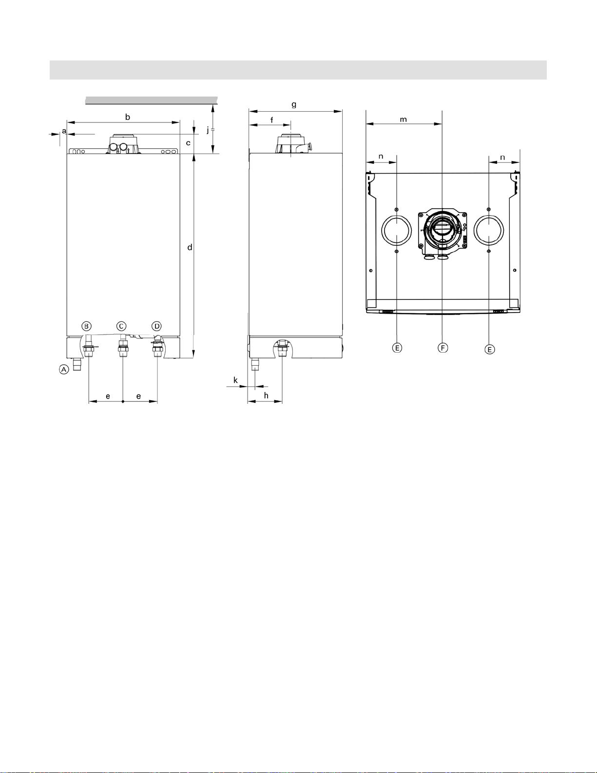
Boiler Dimensions Without Bottom Piping Connections
Dimensions
Front view Side view Top view
Connections Vitodens 100-W, WB1B 26, 35
Legend
Connections
A Condensate drain, plastic hose Ø 0.87” (22 mm)
B Boiler water supply, NPT ¾” (male thread)
C Gas connection, NPT ¾” (male thread)
D Boiler water return, NPT ¾” (male thread)
E Combustion air opening for double pipe system
F Combustion air opening for coaxial system
Note: If using the optional CombiPLUS see page 9.
Dimensions
a See illustration for dimensions
b 15¾” (400 mm)
c 2f” (68 mm)
d 28½” (725 mm)
7
/8” (123 mm)
e 4
f 6d” (156 mm)
g 14d” (360 mm)
h 5” (125 mm)
j 12” (305 mm)
k 1a” (31 mm)
7
/8” (200 mm)
m 7
n 3d” (80 mm)
5601 189 - 01
7
Page 8
Dimensions
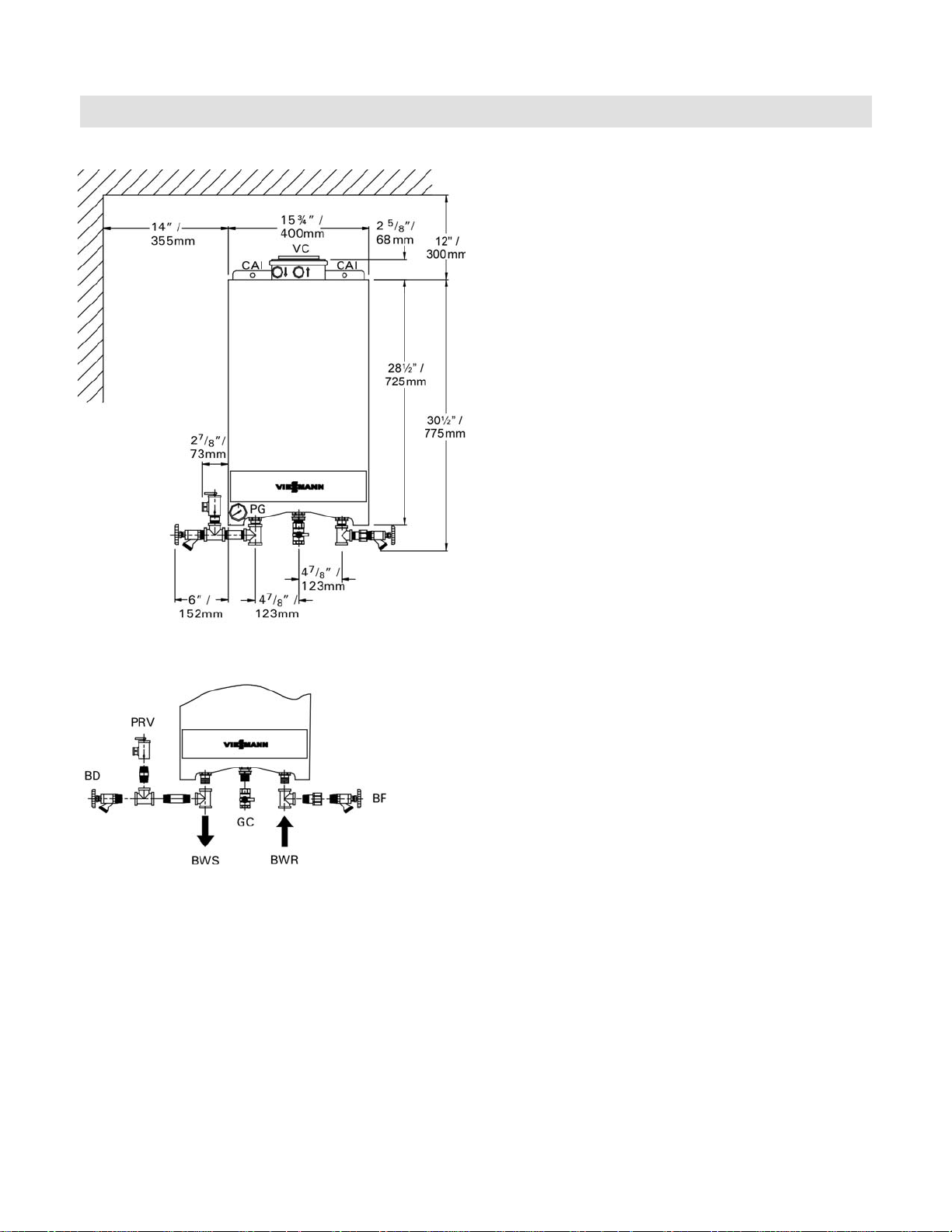
Boiler Dimensions With Piping Connections
Piping connections for Vitodens 100-W,
WB1B 26 and 35 (factory supplied)
Vitodens 100-W, WB1B Technical Data
Note: If using the optional CombiPLUS see page 9.
Legend
BWR Boiler water return, ¾”
BWS Boiler water supply, ¾”
BD Boiler drain
BF Boiler fill
GC Gas connection, ¾” NPTM (male thread)
PRV Pressure relief valve
PG Pressure gage
VC Venting connection
CAI Combustion air inlet connection (optional)
8
5601 189 - 01
Page 9
Vitodens 100-W, WB1B Technical Data
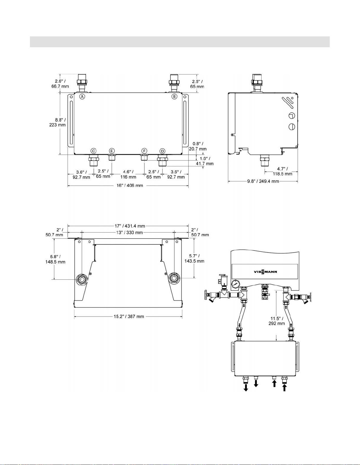
CombiPLUS Dimensions and Piping Connections
CombiPLUS Connections
Dimensions
Front view
Top view
Legend
A Boiler water supply, NPTM ¾” (male thread)
B Boiler water return, NPTM ¾” (male thread)
C System water supply, NPTM ¾” (male thread)
D System water return, NPTM ¾” (male thread)
E DHW, NPTM ½” (male thread)
F DCW, NPTM ½” (male thread)
Side view
with 7”
flex pipes
AB
CDEF
Front view
5601 189 - 01
9
Page 10

Dimensions
Boiler Minimum Clearances
Vitodens 100-W, WB1B Technical Data
Recommended minimum boiler service clearances
Side
Top
Front
Side
5
7”/178mm
Back
Recommended minimum boiler and CombiPLUS Kit
clearances to combustibles
Top Front Rear Left Right Vent
0 0 AL,
CL
AL = Alcove
CL = Closet
1
Refer to the Installation Instructions
*
of the Vitodens Venting System
for details.
Note: The Vitodens 100-W boiler has passed the zero
inches vent clearance to combustibles testing
requirements dictated by the boiler latest
Harmonized Standard ANSI Z21.13. CSA 4.9.2007
and therefore is listed for zero clearance to
combustibles when vented with a single-wall special
venting system (AL-29-4C material) or UL/ULC-listed
CPVC/PP(s) gas vent material. The zero inches vent
clearance to combustibles for the Vitodens 100-W
boiler supercedes the clearance to combustibles
listing that appears on the special venting system
label.
00 0 0
pipe*
1
CombiPLUS installation options
Min. distance between the boiler and CombiPLUS with
Viessmann supplied 7” flex piping connection fittings.
Note: The maximum distance between
the boiler and the CombiPLUS
is restricted by the communication
cable to 36” (915 mm).
10
Shown is the maximum distance between the boiler
and CombiPLUS using field supplied fittings and pipes.
5601 189 - 01
Page 11

Vitodens 100-W, WB1B Technical Data
Heating Circuit Pumps
Operation
Waterside Flow (boiler circuit)
The Vitodens 100-W is designed only for closed loop,
forced circulation hot water heating systems.
Pressure drop (primary circuit) of Vitodens 100-W
ft. m
Pressure Drop
Flow rate
A low-loss header must be used when the system flow
rate exceeds the maximum (or minimum) flow rate of
the Vitodens 100-W boiler. An alternative method may
be used, such as primary secondary piping using closely
spaced tees.
A low-loss header offers additional
benefits not provided by a pair of closely spaced tees.
Viessmann strongly recommends and prefers the use
of a low-loss header over closely spaced tees.
Please see page 18 for details.
Use standard friction loss method for pipe sizing.
Observe boiler maximum and minimum flow rate limitations.
If system flow rate exceeds boiler maximum flow rate
(as stated on page 18) or if system flow rate is unknown,
Viessmann strongly recommends the installation of
a low-loss header. See page 18 for low-loss header
information or refer to the Vitodens Venting System
Installation Instructions.
USGPM
L/h
Heating circuit pumps (field supplied)
Recommended heating pumps with Vitodens 100-W,
WB1B 26, 35 (without an optional CombiPLUS).
Grundfos 15-58 (3-speed)
Taco 00R
or equivalent
Refer to the graph for the proper waterside boiler friction
loss calculations.
IMPORTANT
Pump selection must be based on accurate system flow
and pressure drop calculations (including DHW sizing).
5601 189 - 01
11
Page 12

Operation
Vitodens 100-W, WB1B Technical Data
Heating Circuit Pumps (continued)
CombiPLUS built-in pump
Grundfos UPS15-78 three speed heating circuit/DHW production pump for Vitodens 100 WB1B 26, 35 boilers
(in the factory setting, the pump speed is preset to ‘speed three’)
Speed Three
Speed Two
Speed One
Head H (ft of wc)
Flow Q (gpm)
Performance chart courtesy of Grundfos
Pump Model Grundfos UPS15-78
Rated voltage VAC 115
Rated current A max. 1.15
A min. 0.8
Capacitor
Power consumption W max. 130
CombiPLUS built-in pump, Grundfos UPS15-78 residual head pressure
Residual head of built-in three speed pump used with Vitodens 100 WB1B 26, 35
F
W min. 80
8
12
Head H (ft of wc)
Flow Q (gpm)
5601 189 - 01
Page 13

Vitodens 100-W, WB1B Technical Data
Heating Circuit Pumps (continued)
Operation
DHW Production Planning
With the CombiPLUS for instantaneous DHW heating
or with DHW connections for DHW production via a
stand-alone DHW storage tank, the Vitodens 100 boiler
series offers the right solution for every need.
Various factors must be taken into account when
designing the DHW system, and when deciding between
the DHW production with integrated CombiPLUS and the
Such factors are:
DHW requirement, level of comfort and convenience
Number of draw points
Distance of draw points from the boiler/DHW storage tank
System retrofit
Space requirements
standard heating boiler with DHW production via a standalone DHW storage tank.
Options
DHW requirement,
level of comfort and
convenience
Gas-fired boiler
with instantaneous
CombiPLUS
production
DHW requirement for an apartment + +
DHW requirement for a single-family house 0 +
Central DHW requirement for a multi-family house - +
Gas-fired standard
heating boiler
with stand-alone
DHW storage tank
Decentralized DHW requirement for a multi-family house + +
Number of draw points One draw point + 0
Several draw points, non-simultaneous use + 0
Several draw points, simultaneous use - +
Distance of draw
points from the boiler/
DHW storage tank
Up to 23 ft. (7 m) (without DHW recirculation line) + With DHW recirculation line - +
System retrofit DHW storage tank already installed - +
Replacement of existing Combi boiler + -
Space requirements Minimal space available (installation in alcove) + 0
Adequate space available (boiler room) + +
5601 189 - 01
+ (recommended)
0 (recommended in certain cases)
- (not recommended)
13
Page 14

Operation
Vitodens 100-W, WB1B Technical Data
Heating Circuit Pumps (continued)
Domestic Hot Water Production via Instantaneous DHW Plate Heat Exchanger (CombiPLUS)
The CombiPLUS is equipped with an electronically controlled instantaneous DHW plate heat exchanger.
The comfort control function (if selected) ensures that the instantaneous DHW plate heat exchanger is kept warm.
This translates into immediate availability of domestic hot water at any required temperature level.
Technical Data DHW Plate Heat Exchanger
See page 5 in this manual for technical data.
CombiPLUS heat exchanger performance
DHW supply temperature for WB1B 26 (with mixed water)
DHW supply temperature (ºF)
DHW flow rate (GPM)
DHW supply temperature for WB1B 35 (with mixed water)
DHW supply temperature (ºF)
Legend
A DHW output temperature
B DHW/DCW mixing zone
C DHW output temperature at the tap
D Max. flow (restriction by flow limiter)
This chart illustrates the changes in the outlet temperature,
subject to the flow rate at the tap.
If greater volume (max. flow rate through heat exchanger=
2.6 GPM) of water is required, cold water needs to be
mixed which reduces the outlet temperature.
Curve is only applicable for a DCW inlet temperature of
56º F and a boiler input of 91,000 MBH (Vitodens 100-W,
WB1B 26).
Max. recovery rate @ DHW temperature of 140º F = 1.7 GPM
Min. flow through the heat exchanger for boiler start= 0.4 GPM
This chart illustrates the changes in the outlet temperature,
subject to the flow rate at the tap.
If greater volume (max. flow rate through heat exchanger=
3.6 GPM) of water is required, cold water needs to be
mixed which reduces the outlet temperature.
Curve is only applicable for a DCW inlet temperature of
56º F and a boiler input of 118,000 MBH (Vitodens 100-W,
WB1B 35).
Max. recovery rate @ DHW temperature of 140º F = 2.4 GPM
Min. flow through the heat exchanger for boiler start= 0.4 GPM
DHW flow rate (GPM)
DHW supply temperature for WB1B 35 (with mixed water)
DHW supply temperature (ºF)
DHW flow rate (GPM)
14
This chart illustrates the changes in the outlet temperature,
subject to the flow rate at the tap.
If greater volume (max. flow rate through heat exchanger=
3.4 GPM) of water is required, cold water needs to be
mixed which reduces the outlet temperature.
Curve is only applicable for a DCW inlet temperature of
40º F and a boiler input of 118,000 MBH (Vitodens 100-W,
WB1B 35).
Max. recovery rate @ DHW temperature of 140º F = 2.14 GPM
Min. flow through the heat exchanger for boiler start= 0.4 GPM
5601 189 - 01
Page 15

Vitodens 100-W, WB1B Technical Data
Mounting
Installation
Domestic Hot Water Production via DHW Storage Tank
Vitodens 100-W boilers can be used in conjunction with
the stand-alone DHW storage tanks offered by Viessmann
(a separate DHW controller should be field supplied).
All Viessmann DHW storage tanks sold in North America
are available in “Vitosilver” finish only.
Size and select the DHW storage tank based on the
forecast DHW consumption of the building in question.
For further technical information on DHW storage tanks,
see the Vitocell-V Technical Data Manuals.
Mounting Vitodens 100-W boiler Mounting Vitodens 100-W boiler and the CombiPLUS
Start-up and Maintenance
Wall Mounting Information
The Vitodens 100-W (model WB1B 26 and 35) comes with
a template, which allows you to easily mark the location
of the screws for the mounting bracket and the location
of the flue gas pipe on the wall (Viessmann coaxial PPS
vent system only).
The connection to the heating circuits must be made on
site (installation fittings are supplied in the Installation
Fittings package supplied with the boiler).
Start-up and Maintenance
Legend
A Boiler mounting template
5601 189 - 01
Legend
A Boiler mounting template
B CombiPLUS mounting template
15
Page 16

Installation
Condensate
Vitodens 100-W, WB1B Technical Data
Condensate Connection
Install the condensate drain pipe (Ø 7/8” / 22 mm) with
a suitable gradient (min. 2.5%).
Discharge condensate from the boiler into the drainage
system, either directly or (if required) via a neutralization
unit (accessory).
Condensate connection for Vitodens 100-W
model WB1B 26, 35
A Discharge tubing
The condensate drain of the Vitodens 100-W boiler is
equipped with a built-in siphon trap in order to keep flue
gases from being discharged via the condensate drain.
IMPORTANT
Pipe ventilation must take place between the siphon trap
and the neutralization unit (if applicable).
Condensate Drainage and Condensate Neutralization
The condensate formed both in the condensing boiler and
in the flue gas pipe must be discharged into the public
sewage system in accordance with all applicable local
regulations. The condensate produced by a gas-fired
heating system has a pH value between 3 and 4.
Some local codes may require the use of a separate
neutralization unit to treat the aggressive and corrosive
condensate.
With a neutralization unit installed, all condensate from the
boiler and the flue gas pipe enters into the neutralization
unit where it is treated and released into the public sewage
system with a safe pH value of above 6.5.
The use of neutralization granulate (performing the
neutralizing process) is dependent on the operation of the
heating system. To determine the required refill amount,
check granulate level several times during the first year
of operation. In some cases one granulate fill may last
an entire year.
Contact Viessmann to order a neutralization unit for the
Vitodens 100-W boiler.
See Viessmann Price List for order information.
The condensate discharge outlet to the drainage system
connection must be clearly visible. It must be installed with
a suitable gradient and provided with a stench trap.
If the condensate outlet of the Vitodens 100-W boiler is
lower than the drain, a condensate pump must be used.
Only corrosion-resistant materials may be used for
condensate drainage purposes (e.g. braided hose).
Do not use galvanized materials or materials containing
copper for piping, couplings etc. The condensate drain
must have a trap.
Please note that other requirements may apply depending
on local regulations and/or project-specific details.
It is advisable to contact your local waterworks office
(authority responsible for waste water regulations)
well before commencing with the installation of the
neutralization unit in order to establish details of local
regulations that apply.
The following table shows the concentration of (effluent)
substances (e.g. heavy metals) contained in the waste
water from the Vitodens 100-W condensing boiler.
16
Condensate
(effluent) substances
Lead
Cadmium
Chromium
Copper
Nickel
Zinc
Tin
Values measured
in mg/L Vitodens 100
< 0.01
< 0.005
< 0.01
< 0.01
< 0.01
< 0.05
< 0.05
5601 189 - 01
Page 17

Vitodens 100-W, WB1B Technical Data
Venting Options / Electrical Connections
Installation
Vitodens 100-W Venting Options
For detailed information refer to the Vitodens Venting
System Installation Instructions.
Electrical Connection
All electrical connections are made to the boiler’s
integrated power pump module (120 VAC/60 Hz).
Use disconnect means and power service switch
as per local code requirements.
Start-up and Maintenance
Start-up and Maintenance
Control Unit
Function and construction:
The control is integrated into the Vitodens 100-W boiler.
Integrated diagnostic system
For room temperature-dependent operation,
an external control or a room temperature thermostat
may be connected
To control DHW temperature, a separate DHW
controller may be connected
External heat demand
0-10 V (with open therm only)
Viessmann outdoor temperature sensor (field wiring)
Open Therm (field wiring)
CombiPLUS instantaneous DHW control
The control unit consists of:
LCD Display
Selector dial for boiler water temperature adjustment
Selector dial for service setting
Temperature adjustable high limit
Boiler temperature sensor
Burner fault display
Burner fault reset
Pressure gage
Fuse
Boiler temperature sensor
The boiler temperature sensor is connected to the control
unit and built into the boiler.
Frost protection
Frost protection is continuously active. The burner is
switched ON when the boiler water temperature reaches
41° F (5° C) and is switched OFF again when the boiler
water temperature reaches at least 59° F (15° C)
[but not more than 68° F (20° C)].
5601 189 - 01
For details on the control, refer to the
Vitodens 100-W Operating Instructions.
17
Page 18

Installation
Accessories
Accessories for the Vitodens 100-W
Neutralization Unit for Single-Boiler Applications
with neutralizing granulate for Vitodens 100-W, WB1B 26, 35
Part No. 7134 231
Low-Loss Header
- Type 80/50, Part No. 7134 791
[max. flow rate 17.6 GPM (4 m3/h)]
- Type 120/80, Part No. 7134 792
[max. flow rate 35.2 GPM (8 m3/h)]
A low-loss header offers additional benefits
not provided by a pair of closely spaced
tees. Viessmann strongly recommends
and prefers the use of a low-loss header
over closely spaced tees. When used in
conjunction with the Vitodens 100-W
boiler, the low-loss header acts as
hydraulic break, decoupling boiler and
system circuits from each other (no
sensor required). It is recommended to
use the low-loss header in applications in
which the total system flow rate exceeds
the maximum or falls below the minimum
flow rate of the Vitodens 100-W boiler.
For maximum boiler flow rates, see the table on page 11
in this manual.
Viessmann strongly recommends the use of a low-loss
header in cases where the system head and flow rates
are unknown.
In addition, the low-loss header helps eliminate air and
debris [D] from the heating system. See illustrations for
Low-loss header design and the principle of operation.
Product may not look exactly as illustrated.
Vitodens 100-W, WB1B Technical Data
V
primary
V
V
bypass
secondary
Prinicpal of operation
The low-loss header is available in the following sizes.
Select the size based on the maximum system flow rate
of your application.
Model No. Max. system flow rate
Type 80/50 17.6 GPM (4 m3/h)
Type 120/80 35.2 GPM (8 m3/h)
Legend
AB Air Bleed DV Drain Valve
BR Boiler Return SR System Return
BS Boiler Supply SS System Supply
BY Bypass
(with laminar flow)
TS Viessmann Temp.
Sensor (not used)
D Debris and/or air SW Sensor Well
T1 Boiler supply temp. T3 System supply temp.
T2 Boiler return temp. T4 System return temp.
V
V
V
Q
Q
V
Boiler circuit flow rate
primary
secondary
bypass Bypass flow rate
primary Heat supplied by boiler
secondary Heat consumed by system
primary < Vsecondary
Heating circuit flow rate
T1 > T3
T2 = T4
Q
primary = Qsecondary
T1 176° F (80° C)
V
secondary=Vprimary+Vbypass
18
Low-loss header design
IMPORTANT
When installing a low-loss header, system mixed supply
temperature (T3) must be calculated as follows
Product may not look exactly as illustrated.
5601 189 - 01
Page 19

Vitodens 100-W, WB1B Technical Data
Standard Equipment
Installation
Standard Equipment
The Vitodens 100-W gas-fired condensing boiler with
Inox-Radial heat exchanger surfaces, modulating stainless
steel MatriX cylinder gas burner c/w:
installation fittings with 30 psig pressure relief valve,
air vent and pressure gauge
two fill/drain valves
all mounting hardware
The boiler comes fully piped and pre-wired.
Venting material (coaxial) or single pipe PP(s) is to be
supplied by Viessmann only. Side wall vent installations
must include Viessmann protective screen!
Wall mounting componentry
The following wall mounting components are supplied with
the Vitodens 100-W boiler:
Mounting bracket
Mounting bolts
Installation fittings
Screws for mounting bracket on
- wood studs (2” x 4”)
- metal studs
- brick/concrete wall
How the Vitodens 100-W boiler operates...
The Vitodens 100-W boiler uses a premix combustion
system, which is designed to deliver a certain air-gas
mixture to the burner for complete combustion. The gas
is injected upstream of the blower. The burner and heat
exchanger are part of a forced-draft design. The benefits
of forced-draft systems are lower component
temperatures, direct air-fuel connection (premix) for
improved mixing, and longer service life of the boiler due
to mild to moderate ambient conditions.
The MatriX cylinder burner, blower and the combination
gas valve are factory calibrated and pre-adjusted. A
pneumatic link between combustion air and gas flows
guarantees optimal boiler performance at all firing rates.
Blower speed is automatically increased or decreased
based on heat demand, thereby regulating the amount
of combustion air drawn. The pneumatic link between air
and gas introduces the required amount of gas for optimal
combustion to meet the current heat demand, based on
a linear relationship between P air and P gas.
Installation Examples
IMPORTANT
The examples on the following pages depict possible
piping layouts of the Vitodens 100-W boiler.
Please note that the following examples are simplified
conceptual drawings only!
Piping and necessary componentry must be field
verified. A low water cut-off (LWCO) must be installed
where required by local codes. Proper installation and
functionality in the field is the responsibility of the heating
contractor.
5601 189 - 01
19
Page 20

Installation
System Layout 1
Vitodens 100-W, WB1B Technical Data
Vitodens 100-W, WB1B 26, 35 with one heating circuit
(without optional CombiPLUS)
AV
PRV
System Layout 1 (alternate option)
Maximum Flow Rates
Model WB1B 26 35
t
Output Btu/h 83,000 108,000
30° F rise (GPM) 5.5 --35° F rise (GPM) 4.7 6.2
40° F rise (GPM) 4.2 5.4
Note: The use of a low-loss header is recommended if the
water flow rate is less than 1.7 GPM (400 L/h) or
more than 6.2 GPM (1400 L/h).
The low-loss header is available as accessory part.
Note: Heating circuit C in the examples should be designed
to 30º F to 40º F (16.7º C to 22.2º C). For lesser
delta T design, system layout designer must use
one of the examples (3 or 4) on the following pages.
IMPORTANT
Ensure that a pressure activated by-pass is installed if
there are system component(s) in C that may isolate the
flow to the pump D.
AV
PRV
Legend
AV Air vent
PRV Pressure relief valve
A Vitodens 100-W
B Room thermostat
C Heating circuit
D Heating circuit pump (field supplied)
E Expansion tank
F Pressure Activated By-Pass
20
5601 189 - 01
Page 21

Vitodens 100-W, WB1B Technical Data
System Layout 2
Installation
Vitodens 100-W, WB1B 10-26, 10-35 with...
- DHW storage tank
- low-loss header
- one heating circuit
AV
PRV
TPV
Legend
AV Air vent
PRV Pressure relief valve
TPV Temperature and pressure relief valve
A Vitodens 100-W gas-fired condensing boiler
B External boiler/DHW controller (field supplied)
C Heating circuit
D Heating circuit pump (field supplied)
E DHW storage tank
F DHW tank temperature aquastat or sensor
G DHW circulating pump (field supplied)
H Low-loss header
K Expansion tank
L Primary pump (boiler circuit, field supplied)
with low-loss header only
IMPORTANT
Primary pump must pump into the boiler (as illustrated).
Note: The use of a low-loss header is recommended if the
water flow rate is less than 1.7 GPM (400 L/h) or
more than 6.2 GPM (1400 L/h).
The low-loss header is available as accessory part.
Maximum Flow Rates
Model WB1B 26 35
t
Output Btu/h 83,000 108,000
30° F rise (GPM) 5.5 --35° F rise (GPM) 4.7 6.2
40° F rise (GPM) 4.2 5.4
IMPORTANT
DHW supply and return piping between boiler DHW
connections and the Viessmann DHW tank connections,
shall be a minimum of 1” nominal pipe diameter
(irrespective of the ¾” DHW connection outlet sizes
provided on the boiler and the DHW tank).
This ensures that the head of the pump is fully utilized
to overcome the resistance of the DHW heat exchanger
coil and to provide sufficient water flow to the boiler
heat exchanger.
In non-Viessmann DHW tank applications, perform, in
addition to the above, accurate calculations for DHW
tank coil pressure drop versus boiler pump head to ensure
sufficient water flow to the boiler heat exchanger.
Failure to heed the above instructions may cause boiler
short-cycling and inadequate DHW supply.
5601 189 - 01
21
Page 22

Installation
System Layout 3
Vitodens 100-W, WB1B 10-26, 10-35 with DHW storage
tank and one heating circuit
AV
PRV
Vitodens 100-W, WB1B Technical Data
IMPORTANT
Primary pump must pump into the boiler (as illustrated).
Note: The use of a low-loss header is recommended if the
water flow rate is less than 1.7 GPM (400 L/h) or
more than 6.2 GPM (1400 L/h).
The low-loss header is available as an accessory part.
Maximum Flow Rates
Model WB1B 26 35
t
Output Btu/h 83,000 108,000
30° F rise (GPM) 5.5 --35° F rise (GPM) 4.7 6.2
40° F rise (GPM) 4.2 5.4
IMPORTANT
TPV
Legend
AV Air vent
PRV Pressure relief valve
TPV Temperature and pressure relief valve
A Vitodens 100-W gas-fired condensing boiler
B External boiler/DHW controller (field supplied)
C Heating circuit
D Heating circuit pump (field supplied)
E DHW storage tank
F DHW tank temperature aquastat or sensor
G DHW circulating pump (field supplied)
H Closely spaced tees, 4x pipe Ø or 12” (305 mm)*
K Expansion tank
L Primary pump (boiler circuit, field supplied)
with low-loss header only
DHW supply and return piping between boiler DHW
connections and the Viessmann DHW tank connections,
shall be a minimum of 1” nominal pipe diameter
(irrespective of the ¾” DHW connection outlet sizes
provided on the boiler and the DHW tank).
This ensures that the head of the pump is fully utilized
to overcome the resistance of the DHW heat exchanger
coil and to provide sufficient water flow to the boiler
heat exchanger.
In non-Viessmann DHW tank applications, perform, in
addition to the above, accurate calculations for DHW
tank coil pressure drop versus boiler pump head to
ensure sufficient water flow to the boiler heat exchanger.
Failure to heed the above instructions may cause boiler
short-cycling and inadequate DHW supply.
* A low-loss header offers additional benefits not
provided by a pair of closely spaced tees.
Viessmann strongly recommends and prefers the
use of a low-loss header over closely spaced tees.
See page 18 for details.
22
5601 189 - 01
Page 23

Vitodens 100-W, WB1B Technical Data
System Layout 4
Installation
Vitodens 100-W, WB1B 26, 35 with one heating circuit
and the CombiPLUS
Maximum Flow Rates
Model WB1B 26 35
t
Output Btu/h 83,000 108,000
30° F rise (GPM) 5.5 --35° F rise (GPM) 4.7 6.2
40° F rise (GPM) 4.2 5.4
Note: The use of a low-loss header is recommended if the
water flow rate is less than 1.7 GPM (400 L/h) or
more than 6.2 GPM (1400 L/h).
The low-loss header is available as accessory part.
Built-in pump residual head for the heating system
side is 7.5 ft. of water column at the boiler
maximum flow rate of 6.2 GPM.
Note: Heating circuit C in the examples should be designed
to 30º F to 40º F (16.7º C to 22.2º C). For lesser
delta T design, system layout designer must use
one of the examples (5 or 6) on the following pages.
Legend
AV Air vent
PRV Pressure relief valve (boiler)
PRV*Pressure relief valve (DHW 150 psi)
WSE Water softner equipment
A Vitodens 100-W
B Room thermostat
C Heating circuit
D CombiPLUS
E Expansion tank
5601 189 - 01
23
Page 24

Installation
System Layout 5
Vitodens 100-W, WB1B Technical Data
Vitodens 100-W, WB1B 10-26, 10-35 with...
- CombiPLUS Kit
- low-loss header
- one heating circuit
Note: The use of a low-loss header is recommended if the
water flow rate is less than 1.7 GPM (400 L/h) or
more than 6.2 GPM (1400 L/h).
The low-loss header is available as accessory part.
Maximum Flow Rates
Model WB1B 26 35
t
Output Btu/h 83,000 108,000
30° F rise (GPM) 5.5 --35° F rise (GPM) 4.7 6.2
40° F rise (GPM) 4.2 5.4
Legend
AV Air vent
PRV Pressure relief valve (boiler)
PRV*Pressure relief valve (DHW 150 psi)
WSE Water softener equipment
A Vitodens 100-W gas-fired condensing boiler
B External boiler / system controller (field supplied)
C Heating circuit
D Heating circuit pump (field supplied)
E CombiPLUS
F LLH
G Expansion tank
24
5601 189 - 01
Page 25

Vitodens 100-W, WB1B Technical Data
System Layout 6
Installation
Vitodens 100-W, WB1B 10-26, 10-35 with CombiPLUS
and one heating circuit without LLH
Note: The use of a low-loss header is recommended if the
water flow rate is less than 1.7 GPM (400 L/h) or
more than 6.2 GPM (1400 L/h).
The low-loss header is available as an accessory part.
Maximum Flow Rates
Model WB1B 26 35
t
Output Btu/h 83,000 108,000
30° F rise (GPM) 5.5 --35° F rise (GPM) 4.7 6.2
40° F rise (GPM) 4.2 5.4
Legend
AV Air vent
PRV Pressure relief valve (boiler)
PRV* Pressure relief valve (DHW 150 psi)
WSE Water softener equipment
A Vitodens 100-W gas-fired condensing boiler
B External system controller (field supplied)
C Heating circuit
D Heating circuit pump (field supplied)
E CombiPLUS
F Closely spaced tees, 4x pipe Ø or 12” (305 mm)*
G Expansion tank
* A low-loss header offers additional benefits not
provided by a pair of closely spaced tees.
Viessmann strongly recommends and prefers the
use of a low-loss header over closely spaced tees.
See page 18 for details.
5601 189 - 01
25
Page 26

Design
System Design Considerations
Vitodens 100-W, WB1B Technical Data
IN THE COMMONWEALTH OF MASSACHUSETTS...
- this product shall be installed by a licensed plumber
or gas fitter.
- the flexible connector (if used) may not exceed 36”.
- any level type shutoff used must be of tee handle type.
Boiler location
As a direct vent appliance, the Vitodens 100-W may
be installed for room air independent operation (sealed
combustion) regardless of size and ventilation method of
the room in which it is located.
The Vitodens 100-W may be installed, for example, in the
main living area of a house, in non-ventilated utility rooms,
cupboards, closets and alcoves with no clearance required
from combustible materials, as well as in attics with a
direct outlet for the flue gas/fresh air system. Follow all
local and national codes.
Flue gas system
Viessmann coaxial PPS (Polypropylene - flame retardant)
concentric flue gas/fresh air systems and two-pipe
stainless steel/CPVC systems for room air independent
operation (sealed combustion) and side wall venting are
tested to ANSI Z21.13 - CSA 4.9 - 2007 standards and
are certified together with the Vitodens 100-W boiler as
a constructional unit. The Vitodens 100-W boiler may
also be vented vertically or horizontally, using a metallic
AL29-4C® special stainless steel, or non-metallic CPVC
single-wall, room air dependent venting system (UL/ULC
listed for category IV).
For a more detailed description of the direct vent and
single-wall vent system, please refer to the Vitodens
Venting System Installation Instructions.
System layout
The max. boiler water temperature for ...
-space heating is 176° F (80° C).
-DHW production is 176° F (80° C).
To minimize distribution losses, Viessmann
recommends that the heating and domestic hot
water systems be based on a maximum boiler
supply temperature of 158° F (70° C).
Due to the low return temperatures
required for gas condensing, avoid the use of mixing
valves in the heating circuit whenever possible.
If mixing valves are required, e.g. for multi-circuit
systems or underfloor heating systems, only 3-way
mixing valves may be used.
Do not use 4-way mixing valves in a system with
condensing boilers.
Water connections
Vitodens 100-W boilers can be used in any fully pumped
hot water heating system.
Minimum system pressure is 0.8 bar (12 psig).
Chemical corrosion protection products
Corrosion does not typically occur in sealed heating
systems which have been correctly installed and are
correctly operated.
Many manufacturers of plastic pipes recommend the
use of chemical additives. In this case, only commercially
available corrosion protection products that have been
approved for boilers with domestic hot water heating
via single-wall heat exchangers (instantaneous plate
heat exchangers or DHW tanks) may be used.
Flue gas temperature protection
Viessmann coaxial PPS (Polypropylene - flame retardant)
flue pipes used for the Vitodens 100-W are rated for max.
flue gas temperatures of up to 230° F (110° C).
Flue gas temperature protection is also included although
the maximum permissible flue gas temperature will not
be exceeded in any operating condition or in the event of
malfunctioning.
Low water cut-off
A low water cut-off may be required by local codes.
If the boiler is installed above the radiation level, a low
water cut-off device of approved type must be installed
in all instances. An approved low water cut-off device that
meets government and local regulations must be provided
by the heating contractor.
Do not install an isolation valve between the boiler and the
low water cut-off. The Vitodens 100-W boiler has a built-in
flow switch, which may be accepted by local codes in lieu
of a low water cut-off.
26
Underfloor heating systems
For underfloor heating systems Viessmann recommends
the use of plastic tubing with an oxygen diffusion barrier
in order to prevent the diffusion of oxygen through tubing.
If plastic tubing without an oxygen diffusion barrier is used
in underfloor heating systems, Viessmann recommends
that such systems be separated from the boiler with a
heat exchanger.
Water Conditions for DHW CombiPLUS
Media: pH value 6.5 to 12, glycol max. 30%
DHW (max. hardness): Chloride up to 250 mg/L
Hardness up to 358 ppm
3
(= max. 0.278 kg/m
lime deposit)
5601 189 - 01
Page 27

Vitodens 100-W, WB1B Technical Data
System Design Considerations (continued)
Design
Oxygen diffusion barrier underfloor tubing
The boiler warranty does not cover leaks resulting from
corrosion caused by the use of underfloor plastic tubing
without an oxygen diffusion barrier. Such systems must
have the non-oxygen diffusion barrier tubing separated
from the boiler with a heat exchanger.
Viessmann recommends the use of underfloor plastic
tubing with an oxygen diffusion barrier.
Water quality
Treatment for boiler feed water should be considered in
areas of known problems, such as where a high mineral
content and hardness exist. In areas where freezing might
occur, an antifreeze may be added to the system water
to protect the system. Please adhere to the specifications
given by the antifreeze manufacturer.
Do not use automotive silicate based antifreeze. Please
observe that an antifreeze/water mixture may require a
backflow preventer within the automatic water feed and
influence components such as diaphragm expansion tanks,
radiation, etc. Maximum antifreeze content is 50% for the
Vitodens 100-W boiler (when used with DHW CombiPLUS
max. content is 30%). Do not use antifreeze other than
specifically made for hot water heating systems.
The system may also contain components which might
be negatively affected by antifreeze.
Check total system frequently when filled with antifreeze.
Advise system operator/ultimate owner that system is filled
with a glycol mix.
The heating contractor must provide a MSDS (Material
Safety Data Sheet) for the antifreeze used to the system
operator/ultimate owner.
Warranty
Our warranty does not cover damages resulting from
the following:
- installation or service by unqualified and unlicensed
personnel.
- attempting to perform any repair work on
the boiler other than that mentioned in the boiler
literature.
- tampering with or attempting to readjust
the factory settings of the combination gas valve
- leaks resulting from corrosion caused by
the use of underfloor plastic tubing without an
oxygen diffusion barrier.
For detailed warranty information, please read warranty
sheet supplied with product.
5601 189 - 01
27
Page 28

Venting
Coaxial System
Vitodens 100-W, WB1B Technical Data
Intake
Intake
Flue
Intake Intake
Flue
Coaxial, horizontally vented, PP(s) (Viessmann supplied)
Vent system
diameter (mm)
Maximum
equivalent
length ft. (m)
60/100 80/125 100/150
82 (25) 98 (30) 118 (36)
28
Coaxial, vertically vented, PP(s) (Viessmann supplied)
Vent system
diameter (mm)
Maximum
equivalent
length ft. (m)
60/100 80/125 100/150
82 (25) 98 (30) 118 (36)
5601 189 - 01
Page 29

Vitodens 100-W, WB1B Technical Data
Two Pipe System
Venting
Two pipe system (room air independent) horizontally vented
Flue
Intake
Vent system
diameter (in)
Maximum
equivalent
length ft. (m)
*stainless steel is not available in 2”
Flue
Intake
Two pipe system (room air independent) vertically vented
Vent system
diameter (in)
Maximum
equivalent
length ft. (m)
*stainless steel is not available in 2”
Combustion air: CPVC, PVC, ABS and stainless steel
(field supplied)
Flue gas: CPVC and stainless steel (field supplied)
PP(s): (Viessmann supplied)
Combustion air: CPVC, PVC, ABS and
stainless steel (field supplied)
Flue gas: CPVC and stainless steel
(field supplied)
PP(s): (Viessmann supplied)
2* 3 4
86 (20) 164 (50) 200 (61)
2* 3 4
86
164
(20)
(50)
200
(61)
Flue
5601 189 - 01
Two pipe system (room air independent) hybrid
Vent system
diameter (in)
Maximum
equivalent
length ft. (m)
*stainless steel is not available in 2”
Combustion air: CPVC, PVC, ABS and stainless steel
(field supplied)
Flue gas: CPVC and stainless steel (field supplied)
PP(s): (Viessmann supplied)
Intake
2* 3 4
86 (20) 164 (50) 200 (61)
29
Page 30

Venting
Single Pipe System
Vitodens 100-W, WB1B Technical Data
Intake
Intake
Flue
Flue
Single pipe system (room air dependant) horizontally vented
Vent system
diameter (in)
Maximum
equivalent
length ft. (m)
*stainless steel is not available in 2”
CPVC and stainless steel (field supplied)
PP(s) (Viessmann supplied)
2* 3 4
86 (20) 164 (50) 200 (61)
30
Single pipe system (room air dependant) vertically vented
Vent system
diameter (in)
Maximum
equivalent
length ft. (m)
*stainless steel is not available in 2”
CPVC and stainless steel (field supplied)
PP(s) (Viessmann supplied)
IntakeIntake
2* 3 4
86 (20) 164 (50) 200 (61)
5601 189 - 01
Page 31

Vitodens 100-W, WB1B Technical Data
Flexible System
Venting
Flue
Intake
Flexible two pipe system (room air independent)
Vent system
diameter (in)
Maximum
equivalent
length ft. (m)
Combustion air: CPVC, PVC, ABS and stainless steel
(field supplied)
Flue gas: PP(s) (Viessmann supplied)
80 flex
2” comb.
65 (20) 123 (37) 150 (46)
80 100
Intake
Intake
Flue
Flexible single pipe system (room air dependant)
Vent system
diameter (in)
Maximum
equivalent
length ft. (m)
PP(s) (Viessmann supplied)
80 100
123 (37) 150 (46)
5601 189 - 01
31
Page 32

Quick Reference
°C °F
-40 -40
-35 -31
-25 -13
-20 -4
-18 0
-16 +3
-14 +7
-12 +10
-10 +14
-9 +16
-8 +18
-7 +19
-6 +21
-5 +23
-4 +25
-3 +27
-2 +28
-1 +30
0 +32
+1 +34
+2 +36
+3 +37
+4 +39
+5 +41
+6 +43
+7 +45
+8 +46
+9 +48
+10 +50
+12 +54
+14 +57
+16 +61
+18 +64
+20 +68
+25 +77
+30 +86
+35 +95
+40 +104
+50 +122
+60 +140
+70 +158
+80 +176
+90 +194
+100 +212
+110 +230
Vitodens 100-W, WB1B Technical Data
Printed on environmentally friendly
(recycled and recyclable) paper.
Technical information subject to change without notice.
5601 189 - 01
 Loading...