

Page 1
Bedienungsanleitung
Innovation,
Operation Manual
4565 H0
9565 0
Weichenlaterne mit Adapter für
Universalantrieb 4560
Switchpoint light with adapter for
universal drive 4560
1. Wichtige Hinweise / Important information ................................................ 2
2. Einleitung / Introduction ............................................................................. 3
3. Einbau / Mounting ...................................................................................... 3
4. Anschluss / Connection ............................................................................. 6
5. Gewährleistung / Warranty ........................................................................ 7
6. Technische Daten / Technical data ............................................................ 7
die bewegt!
Page 2
1. Wichtige Hinweise
Bitte lesen Sie vor der ersten Anwendung des Produktes
bzw. dessen Einbau diese Bedienungsanleitung aufmerksam durch. Bewahren Sie diese auf, sie ist Teil des
Produktes.
1.1 Sicherheitshinweise
Vorsicht:
Verletzungsgefahr!
Für die Montage sind Werkzeuge nötig.
Stromschlaggefahr!
Die Anschlussdrähte niemals in eine Steckdose einführen! Verwendetes Versorgungsgerät (Transformator,
Netzteil) regelmäßig auf Schäden überprüfen. Bei Schäden am Versorgungsgerät dieses keinesfalls benutzen!
Alle Anschluss- und Montagearbeiten nur bei abgeschal
teter Betriebsspannung durchführen!
Ausschließlich nach VDE/EN gefertigte Modellbahntransformatoren verwenden!
Stromquellen unbedingt so absichern, dass es bei einem
Kurzschluss nicht zum Kabelbrand kommen kann.
1.2 Das Produkt richtig verwenden
Dieses Produkt ist bestimmt:
- Zum Einbau in Modelleisenbahnanlagen und Dioramen.
- Zum Anschluss an einen Modellbahntransformator
(z. B. Art. 5200) bzw. an eine Modellbahnsteuerung mit
zugelassener Betriebsspannung.
- Zum Anbau an den Universalantrieb Art. 4560.
- Zum Betrieb in trockenen Räumen.
Jeder darüber hinausgehende Gebrauch gilt als nicht bestimmungsgemäß. Für daraus resultierende Schäden haftet
der Hersteller nicht.
-
1. Important information
Please read this manual completely and attentively before
using the product for the rst time. Keep this manual. It is
part of the product.
1.1 Safety instructions
Caution:
Risk of injury!
Tools are required for installation.
Electrical hazard!
Never put the connecting wires into a power socket!
Regularly examine the transformer for damage. In case
of any damage, do not use the transformer.
Make sure that the power supply is switched off when
you mount the device and connect the cables!
Only use VDE/EN tested special model train transformers for the power supply!
The power sources must be protected to avoid the risk
of burning cables.
1.2 Using the product for its correct purpose
This product is intended:
- For installation in model train layouts and dioramas.
- For connection to an authorized model train transformer
(e. g. item 5200) or a digital command station.
- For mounting to the universal drive item 4560.
- For operation in dry rooms only.
Using the product for any other purpose is not approved
and is considered inappropriate. The manufacturer is not
responsible for any damage resulting from the improper
use of this product.
2
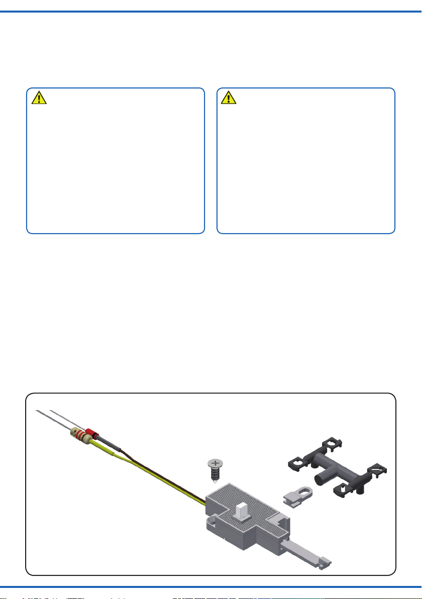
Abb. 1
Fig. 1
2.
1.
4. - Nur bei Art. 4565:
Mitnehmer für H0
Fleischmann-Weichen.
- Only with item 4565:
Coupling means for H0
Fleischmann points.
3.
Page 3
1.3 Packungsinhalt überprüfen
Kontrollieren Sie den Lieferumfang auf Vollständigkeit (Abb. 1):
- Weichenlaterne mit Adapter und LED mit Anschlusskabeln, Vorwiderstand und Schutzdiode (1)
- Schraube, Ø 2,2 x L 6,5 mm (2)
- Spritzling mit Laternengehäuse (3)
- Nur bei Art. 4565: Mitnehmer zum Betrieb von H0
Fleischmann-Weichen (4)
- Anleitung
1.3 Checking the package contents
Check the contents of the package for completeness (g. 1):
- Switchpoint light with adapter and LED with connection
cables, serial resistor and protective diode (1)
- Screw, Ø 2,2 x L 6,5 mm (2)
- Injection-moulded part with light housing (3)
- Only with item 4565: Coupling means for operation of H0
Fleischmann turnouts (4)
- Manual
2. Einleitung
Diese Weichenlaterne wird über ihren zugehörigen
Adapter an der Stirnseite des Universalantriebs Art. 4560
angebaut und verwendet dessen Längsabtrieb. An der
Seite des Adapters befindet sich wiederum ein eigener
Längsabtrieb – die volle Funktionalität des Universalantriebs Art. 4560 bleibt somit erhalten. Die Laterne wird
durch eine weiße LED beleuchtet. Sie wird mit der Weiche
in die jeweils richtige Stellung umgeschaltet und zeigt dem
Lokführer die Weichenstellung an. Die vorbildgerechte und
helle Anzeige der jeweiligen Weichenstellung wertet besonders Weichenstraßen und Bahnhofsvorfelder optisch stark
auf. Ein Gehäuse für rechts- und linksgerichtete Weichen
ist im Lieferumfang enthalten.
2.1 Geeignete Weichen
Die H0 Weichenlaterne mit Adapter (Art. 4565) ist für den
Betrieb mit allen H0 Weichen geeignet, die 0 Weichenlaterne mit Adapter (Art. 9565) mit allen Spur 0 Weichen, welche
mit dem Universalantrieb Art. 4560 bedient werden können
(siehe Anleitung Art. 4560).
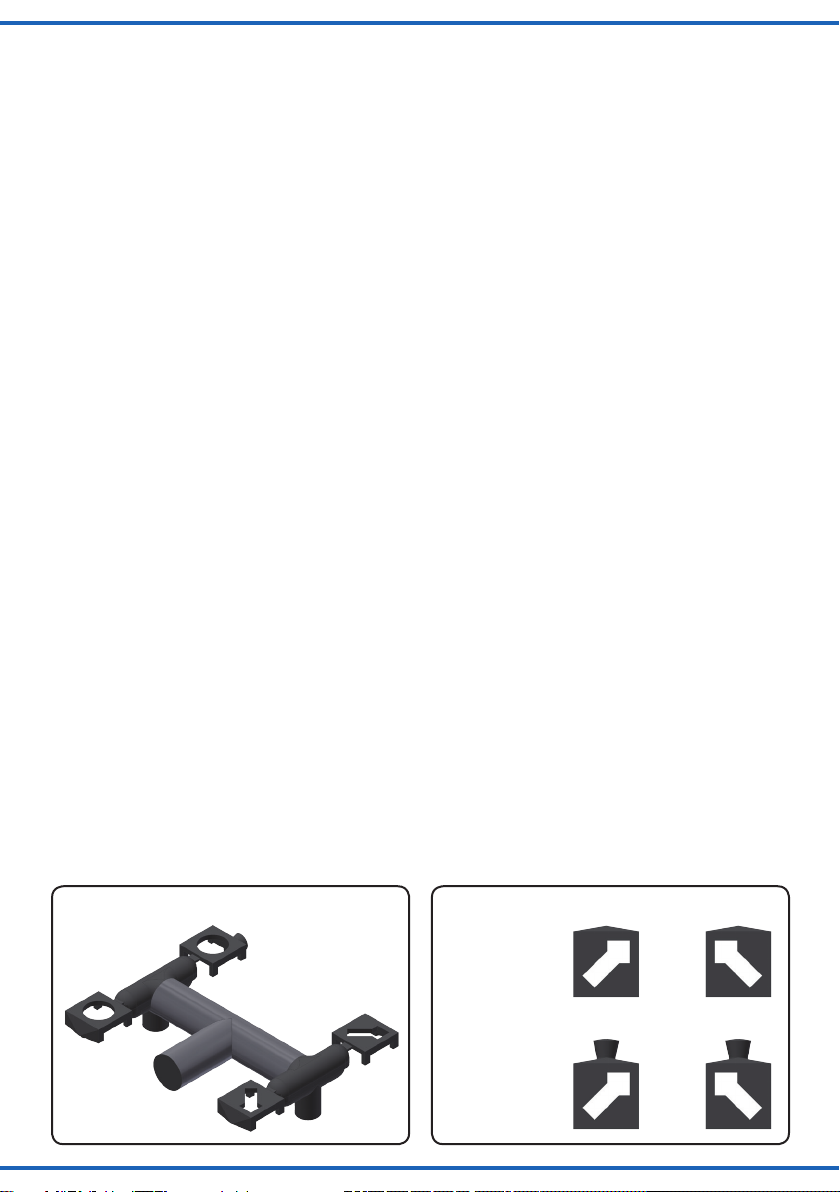
3. Einbau
- Lösen Sie die Laternengehäuse vorsichtig mit einem
Seitenschneider vom Spritzling (Abb. 2.1).
- Wählen Sie ein zu Ihrem Weichenabzweig passendes Gehäuse (Abb. 2.2, 2.2.1). Sie können wählen
zwischen einem Gehäuse mit und ohne Kamin.
- Geben Sie etwas Klebstoff auf die gewählten Bauteile
des Gehäuses und stecken Sie die beiden Hälften auf
dem Leuchtkörper des Adapters zusammen (Abb. 2.3,
Abb. 2.4).
- Nehmen Sie den oberen Deckel des Universalantriebs
Art. 4560 ab.
2. Introduction
This switchpoint light can be mounted into an adapter on
the longitudinal output of item 4560 universal drive. The
adapter itself provides a longitudinal output, so the full
functionality of item 4560 universal drive is preserved.
A white LED provides illumination, the connection is
achieved via cables. The light switches to the correct position together with the turnout and indicates the position to
the train driver. The realistic and bright display of the turnout directions enhances the optics of any railway station
or shunting yard. A housing for both right- and left-facing
turnouts is included.
2.1 Suitable switches
The H0 switchpoint light with adapter (item 4565) is suitable for all H0 turnouts, the 0 gauge switchpoint light with
adapter (item 9565) for all 0 gauge turnouts that can be
operated with the universal drive item 4560 (also refer to
the manual of item 4560).
3. Mounting
- Carefully remove the lantern housing from the sprue
with a side cutter (fig. 2.1).
- Select the appropriate lantern housing matching your
turnout housing (fig. 2.2, 2.2.1). You may choose between housing with and without chimney.
- Apply some glue to the selected parts and put both
halves of the lantern housing onto the luminous element
of the adapter (fig. 2.3, fig. 2.4).
- Remove the top lid of the universal drive item 4560.
Abb. 2.1
Fig. 2.1
Abb. 2.2
Kaminausführung
Chimney execution
Fig. 2.2
3
Page 4

Abb. 2.2.1
Fig. 2.2.1
Abb. 2.3
3.1 Montage ohne Mitnehmer (Art. 4565, 9565)
- Halten Sie die Weichenlaterne mit Adapter an den Universalantrieb Art. 4560 (Abb. 3.1) und verbinden Sie die
Antriebsstange der Weichenlaterne mit der Mechanik
der längsgerichteten Bewegung des Universalantriebs
(Abb. 3.2).
3.2 Montage mit Mitnehmer (nur bei Art. 4565)
- Nehmen Sie den Seitendeckel der Weichenlaterne mit
Adapter ab (Abb 4.1).
- Passen Sie den Mitnehmer für H0 Fleischmann-Weichen
in die Mechanik der Weichenlaterne ein (Abb. 4.2).
- Halten Sie die Weichenlaterne mit Adapter an den Universalantrieb Art. 4560 (Abb. 4.3) und verbinden Sie die
Antriebsstange der Weichenlaterne mit der Mechanik
der längsgerichteten Bewegung des Universalantriebs
(Abb. 3.2).
Fig. 2.3
Abb. 2.4
3.1 Mounting without coupling means (item 4565, 9565)
- Place the switchpoint light with adapter next to the
universal drive item 4560 (fig. 3.1) and connect the
drive rod of the lantern with the mechanics of the
longitudinal movement of the universal drive (fig. 3.2).
3.2 Mounting with coupling means (only with item 4565)
- Remove the side lid of the switchpoint light with
adapter (fig 4.1).
- Insert the coupling means for the Fleischmann H0 turnout
into the mechanics of the lantern (fig. 4.2).
- Place the switchpoint light with adapter next to the
universal drive item 4560 (fig. 4.3) and connect the
drive rod of the lantern with the mechanics of the
longitudinal movement of the universal drive (fig. 3.2).
Fig. 2.4
- Bohren Sie neben dem Adapter ein Loch (Ø 2,5 mm).
- Stecken Sie die Anschlusskabel der Weichenlaterne von
oben durch das Loch.
- Befestigen Sie die Weichenlaterne mit Adapter mit
der beliegenden Schraube an der Grundplatte.
- Setzen Sie den oberen Deckel des Universalantriebs
Art. 4560 wieder auf (Abb. 3.3, 4.4).
4
- Drill a 2,5 mm hole next to the adapter.
- Insert the connection cables into the hole from above.
- Fix the switchpoint light with adapter with the screw
provided to the ground plate.
- Put the top cover of the universal drive item 4560 (fig.
3.3, 4.4) back in its place.
Page 5

Abb. 3.1
Fig. 3.1
Abb. 3.2
Fig. 3.2
Abb. 3.3
Abb. 4.1
Abb. 4.3
Fig. 4.1
Fig. 4.3
Abb. 4.2
Abb. 4.4
Fig. 3.3
Fig. 4.2
Fig. 4.4
5
Page 6

4. Anschluss
Vorsicht:
Widerstand und Diode an den Enden der Anschlussdrähte
sind für die Funktion erforderlich. Keinesfalls entfernen! Widerstand und Diode nicht mit Isolationsmaterial umhüllen, da
sonst keine ausreichende Kühlung möglich ist!
Schließen Sie die Weichenlaterne an den Lichtausgang eines Modellbahntransformators (z. B. Art. 5200) an (Abb. 5).
Zum Anschluss des Universalantriebs Art. 4560 beachten
Sie bitte dessen Anleitung.
Zum einfachen Ein- und Ausschalten der Weichenlaterne,
verwenden Sie einen Schalter (z. B. Art. 5550).
Gleichspannung: Verbinden Sie die Diode mit dem Plus-Pol
des Netzteils, den Widerstand mit dem Minus-Pol.
Wechselspannung: Bei Betrieb mit Wechselspannung
kann es zu leichtem Flackern kommen. Daher empfehlen wir den Betrieb mit dem Viessmann Powermodul
Art. 5215 (Abb. 6). Ein Powermodul ist ausreichend für
ca. 100 LED-Leuchten oder -Strahler. Verbinden Sie das
Anschlusskabel mit der Diode mit der braunen Anschlussbuchse, das Anschlusskabel mit dem Widerstand mit der
roten Anschlussbuchse.
4. Connection
Caution:
Resistor and diode at the cables are needed for proper
function of the lamp. Never cut them off! Never cover
resistor or diode with insulation material, because they
have to be cooled by surrounding air!
Connect the switchpoint light to the AC output of your
model train transformer (e. g. item 5200 – g. 5).
Please refer to the manual of item 4560 regarding the
connection.
Simply use an ordinary switch such as item 5550 for
switching the lighting of the switchpoint light.
DC voltage: Connect the diode with the positive pole of
the transformer and the resistor with the negative pole.
AC voltage: During operation with AC voltage it may
icker slightly. We recommend to use the Viessmann
power module item 5215 (g. 6) which is sucient
for ca. 100 LEDs or reectors. Connect the cable with the
diode to the brown output socket and the resistor to the
red output socket.
6
Abb. 5
Abb. 6
5200
Lichttransformator
Lichttransformator
Primär
Primär
230 V~
230 V~
Nur für trockene Räume
Nur für trockene Räume
5200
Primär 230 V 50 - 60 Hz
Primär 230 V 50 - 60 Hz
Sekundär max. 3,25 A52 VA
Sekundär max. 3,25 A52 VA
ta 25°CIP 40
ta 25°CIP 40
Gefertigt nach
Gefertigt nach
VDE 0570
VDE 0570
EN 61558
EN 61558
z. B. / e. g. 5200
z. B. / e. g. 5200
Lichttransformator
Primär
230 V~
Primär 230 V 50 - 60 Hz
Sekundär max. 3,25 A52 VA
Nur für trockene Räume
z. B. / e. g. 5200
Sekundär
Sekundär
0-10-16 V~
0-10-16 V~
Fig. 5
gelb / yellow
gelb / yellow
braun
16 V
16 V
10 V
10 V
0 V
0 V
braun
braun
brown
brown
grün / green
grün / green
Universal Ein-Aus-Umschalter
Universal Ein-Aus-Umschalter
viessmann
viessmann
braun
brown
brown
5550
5550
z. B. / e. g. 5550
z. B. / e. g. 5550
Fig. 6
rt bn
T
zu den Decodern
E
viessmann
z. B. / e. g. 5215
gelb / yellow
16 V
5200
10 V
Sekundär
0-10-16 V~
ta 25°CIP 40
0 V
Gefertigt nach
VDE 0570
EN 61558
braun
brown
grün / green
Universal Ein-Aus-Umschalter
viessmann
5550
5215
Powermodul
Braune Massebuchsen
nicht koppeln !
max. 24 V~
ge bn
braun
brown
z. B. / e. g. 5550
Page 7

Viessmann
hnik GmbH
www.viessmann-modell.de
5. Gewährleistung
Jeder Artikel wurde vor Auslieferung auf volle Funktionalität
geprüft. Der Gewährleistungszeitraum beträgt 2 Jahre ab
Kaufdatum. Tritt in dieser Zeit ein Fehler auf und Sie finden
die Fehlerursache nicht, nehmen Sie bitte Kontakt mit uns
auf (service@viessmann-modell.com).Senden Sie uns
den Artikel zur Kontrolle bzw. Reparatur bitte erst nach
Rücksprache zu. Wird nach Überprüfung des Artikels ein
Herstell- oder Materialfehler festgestellt, wird er kostenlos
instandgesetzt oder ausgetauscht. Von der Gewährleistung
und Haftung ausgeschlossen sind Beschädigungen des
Artikels sowie Folgeschäden, die durch unsachgemäße
Behandlung, Nichtbeachten der Bedienungsanleitung, nicht
bestimmungsgemäßen Gebrauch, eigenmächtigen Eingriff,
bauliche Veränderungen, Gewalteinwirkung, Überhitzung
u. ä. verursacht werden.
5. Warranty
Each model is tested as to its full functionality prior to de-
livery. The warranty period is 2 years starting on the date
of purchase. Should a fault occur during this period please
contact our service department (service@viessmann-mod-
ell.com). Please send the item to the Viessmann service
department for check and repair only after consultation.
If we nd a material or production fault to be the cause
of the failure the item will be repaired free of charge or
replaced. Expressively excluded from any warranty claims
and liability are damages of the item and consequential
damages due to inappropriate handling, disregarding the
instructions of this manual, inappropriate use of the model,
unauthorized disassembling, construction modications
and use of force, overheating and similar.
6. Technische Daten
Betriebsspannung: 10 – 16 V AC~
(mit und ohne 5215 Powermodul)
14 – 24 V DC=
13 – 24 V Digitalsignal
Gewicht: ca. 26 g
Höhe: 65 mm
Entsorgen Sie dieses Produkt nicht über den
(unsortierten) Hausmüll, sondern führen Sie
es der Wiederverwertung zu.
Änderungen vorbehalten. Keine Haftung für Druckfehler
und Irrtümer.
Die aktuelle Version der Anleitung finden Sie auf der Viessmann Homepage unter der Artikelnummer.
Modellbauartikel, kein Spielzeug! Nicht geeignet für Kinder
DE
unter 14 Jahren! Anleitung aufbewahren!
Model building item, not a toy! Not suitable for children
EN
under the age of 14 years! Keep these instructions!
Ce n’est pas un jouet. Ne convient pas aux enfants de
FR
moins de 14 ans ! C’est un produit décor! Conservez cette
notice d’instructions!
Não é um brinquedo!Não aconselhável para menores de
PT
14 anos. Conservar o manual de instruções.
Modelltec
Bahnhofstraße 2a
D - 35116 Hatzfeld-Reddighausen
info@viessmann-modell.com
6. Technical data
Operating voltage: 10 – 16 V AC~
(with and without 5215 power module)
14 – 24 V DC=
13 – 24 V digital signal
Weight: ca. 26 g
Height: 65 mm
Do not dispose of this product through (unsorted)
domestic waste, supply it to recycling instead.
Subject to change without prior notice. No liability for
mistakes and printing errors.
You will nd the latest version of the manual on the Viessmann website using the item number.
Modelbouwartikel, geen speelgoed! Niet geschikt voor
NL
kinderen onder 14 jaar! Gebruiksaanwijzing bewaren!
Articolo di modellismo, non è un giocattolo! Non adatto
IT
a bambini al di sotto dei 14 anni! Conservare istruzioni per
l’uso!
Artículo para modelismo ¡No es un juguete! No recomen-
ES
dado para menores de 14 años! Conserva las instrucciones
de servicio!
87860
Stand 03/sw
10/2019
Made in Europe
Ho/Kf
Page 8

Notizen
Notes
8
 Loading...