

Page 1
Gebrauchsanleitung
Manual
Manual
Form-Hauptsignale
zweibegriffig, mit einem Antrieb
Semaphore Block Signals
two-aspect signals, with one drive unit
H0: 4500, 4501, 4505, 4507, 4530, 4531,
4520, 4521, 45061, 45081
TT: 4900, 4901
N: 4400, 4401, 4405
Z: 4800, 4801
1. Wichtige Hinweise ...................................... 2
2. Einleitung ................................................... 2
3. Aufstellung und Bezeichnung .................... 3
4. Funktionskontrolle ...................................... 3
5. Montage ..................................................... 4
6. Anschluss ................................................... 4
7. Fehlersuche & Abhilfe ................................ 8
8. Technische Daten ...................................... 8
1. Important Information ................................. 2
2. Introduction ................................................ 2
3. Marking of Signals ...................................... 3
4. Checking the function ................................. 3
5. Mounting ..................................................... 4
6. Connections ............................................... 4
7. Troubleshooting .......................................... 8
8. Technical Data ............................................ 8
Page 2
2
D
GB
Fig.
1
Abb. 1
Fig. 2
Abb. 2
1. Wichtige Hinweise
Lesen Sie vor der ersten Benutzung des Produktes bzw. dessen Einbau diese Anleitung komplett
und aufmerksam durch. Bewahren Sie diese An
-
leitung auf. Sie ist Teil des Produktes.
Das Produkt richtig verwenden
Das Produkt darf ausschließlich dieser Anleitung
gemäß verwendet werden. Dieses Signalmodell
ist bestimmt
– zum Einbau in Modelleisenbahnanlagen
– zum Anschluss an einen zugelassenen Mo-
dellbahntransformator bzw. an einer damit ver-
sorgten elektrischen Steuerung
– zum Betrieb in trockenen Räumen
Jeder darüber hinausgehende Gebrauch gilt als
nicht bestimmungsgemäß. Für daraus resultierende Schäden haftet der Hersteller nicht.
2. Einleitung
Viessmann-Formsignale zeichnen sich durch vorbildgetreu langsame Flügelbewegung, ihr hervor
ragendes Preis-Leistungs-Verhältnis sowie durch
einfache Montage und Anschlussmöglichkeit aus.
Das vorliegende Formsignal verfügt über einen
elektromagnetischen Antrieb, eine Endlagenabschaltung und über einen Kontakt zur Zugbeein
-
flussung.
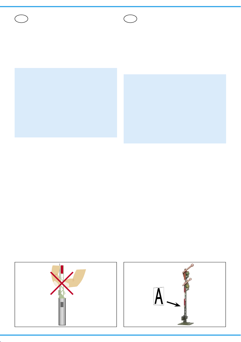
Viessmann-Formsignale haben sehr filigrane Mas-
ten, die sich durch eine perfekte Vorbildtreue auszeichnen. Daher sollten Sie das Signal nie am
Mast anfassen, sondern immer nur an der Bodenplatte bzw. am Antriebszylinder (Abb. 1). Bei ei
nem Ausbau aus der Modellbahnplatte nicht oben
ziehen, sondern das Signal unter der Platte am
Antriebszylinder greifen und nach oben hinaus
schieben!
1. Important Information
Please read this manual prior to first use of the
product resp. its installation! This product must
only be used as required in this manual. Keep this
manual. It is part of the product.
Using the product for it’s correct
purpose
This model of a signal is intended
– for installation in model railroad layouts.
– for connection to an authorized model railroad
transformer or an electrical control system connected to one
– for operation in a dry area
Using the product for any other purpose is not
approved and is considered incorrect. The
manufacturer cannot be held responsible for any
damage resulting from the improper use of this
product.
2. Introduction
Viessmann
-Semaphores have some outstanding
benefits: Prototypical slow arm-movement, very
good price-performance-ratio and they are simple
to mount and connect.
This signal has an electromagnetic drive unit,
end-position-stop and an integrated contact for
train control.
Viessmann-Semaphores have finely detailed
metal mast, which are very sensitive. Therefore
you should never touch the masts but only the
drive unit for installation and deinstallation (Fig. 1)
If you have to unmount the signal, don’t pull the
the signal-mast. Carefully take the drive unit
instead and push it up.
Page 3

3
3. Aufstellung und Bezeichnung
Hauptsignale stehen in Deutschland in der Regel in Fahrtrichtung gesehen rechts vom Gleis.
Zweiflügelige Form-Hauptsignale können als Einoder Ausfahrsignale im Bahnhofsbereich oder als
Blocksignale auf der Strecke eingesetzt werden.
Damit ein Lokführer Signale richtig zuordnen
oder im Störungsfall die richtige Meldung machen
kann, werden die Signale mit einer Buchstaben- /
Zahlenkombination gekennzeichnet. Die Bezeichnung des Signals gibt zusätzlich Auskunft über
seinen Standort. Hier einige Richtlinien zur korrekten Beschriftung:
Blocksignale: Selbstblocksignale werden mit arabischen Zahlen (1, 2, 3, …) bezeichnet. In Richtung der Kilometrierung der Strecke wird mit ungeraden Zahlen vorwärts gezählt (1, 3, 5, …), in der
anderen Richtung mit geraden Zahlen rückwärts
(z. B. 6, 4, 2, …).
Einfahrsignale: In Zählrichtung der Kilometrierung der Strecke werden für Einfahrsignale die
Buchstaben „A“ bis „E“, in Gegenrichtung „F“ bis
„K“ verwendet.
Ausfahrsignale: Ausfahrsignale, die in Zählrichtung stehen, werden mit „N“ bezeichnet. Ausfahrsignale, die entgegen der Zählrichtung stehen,
werden mit „P“ bezeichnet.
Hinter dem Buchstaben eines Ein- oder Ausfahrsignales steht die Ziffer des Gleises, für welches
das Signal gilt.
Damit Sie Ihre Signale korrekt beschriften können,
liegt dem Signal eine Tafel mit selbstklebenden
Bezeichnungsschildern bei. Schneiden Sie das
gewünschte Schild aus, ziehen Sie die Schutzfolie ab und kleben Sie es auf die Nummerntafel am
Mast des Signals (Abb. 2).
Viele weitere Informationen über Signale finden
Sie im Viessmann-Signalbuch, Artikel-Nr. 5299.
4. Funktionskontrolle
Nehmen Sie das Signal vorsichtig aus der Verpackung. Führen Sie vor der Montage eine Funktionskontrolle durch.
Schließen Sie dazu das gelbe Kabel (ohne Markierung) an einem Pol eines 16 V-Modellbahntransformators – z. B. Viessmann 5200 – an.
Verbinden Sie abwechselnd jeweils ein blaues Kabel mit dem anderen Pol des Trafos. Schließen
Sie niemals die blauen Kabel gleichzeitig an.
Das kann zur Zerstörung des Signals führen.
Blau mit roter Markierung:
Signal auf „Halt“ (Hp0), oberer Flügel waagerecht
3. Marking of Signals
Adhesive signs are supplied with the signal.
Simply cut out the desired sign and attach it to
the signal box after removing the protecting foil.
Here are some rules for the correct marking of the
semaphore home signals:
Signals are set on the right side of the track in
germany. Three-aspect-signals can be used in
stations and on the route.
Home signals are marked with an alphanumeric combination The name of the signal gives
information about its position and direction of the
route.
Block Signals: These signals are labeled with
arabic numbers (1, 2, 3, ...). In direction of the
kilometre count, the signals are counted with odd
numbers (e. g. 1, 3, 5, ...). In the opposite direction the signals are counted with even numbers
backwards ( e. g. 6, 4, 2, ...)
Entry Signals: In direction of the kilometre count
of the route, the signals are labeled with the letters
“A” to “E”, in the opposite direction “F” to “K”.
Exit Signals: In direction of the kilometre count
of the route, the signals are labeled with the letter
“N”, in the opposite direction with “P”.
Additional to the letter of an entry- or exit-signal
stands the number of the belonging track.
4. Checking the Function
Remove the signal from the box carefully. Check
all functions prior to installation.
Connect the yellow wire to one of the terminals
of a 16 V transformer (AC/DC) e. g. Viessmann
5200. Then alternately make contact between the
blue cables and the other terminal, but only briefly.
Never connect the blue cables at the same
time to the transformer.
This may destroy the signal.
Connecting the cable results in the following armpositions:
Blue with red marking:
Signal on “Stop” (Hp0), upper arm horizontal,
(if existing: lower arm vertical).
Blue with green marking:
Signal on “Proceed” (Hp1) or on Proceed slowly
(Hp2), upper arm diagonal upwards,
(if existing: lower arm diagonal upwards).
Page 4
4
Abb. 3
Fig. 3
13 mm
90°
Abb. 4
Fig. 4
(wenn vorhanden: unterer Flügel senkrecht)
Blau mit grüner Markierung:
Signal auf „Fahrt“ (Hp1) bzw. Langsamfahrt (Hp2),
oberer Flügel schräg nach oben (wenn vorhanden: unterer Flügel ebenfalls schräg nach oben)
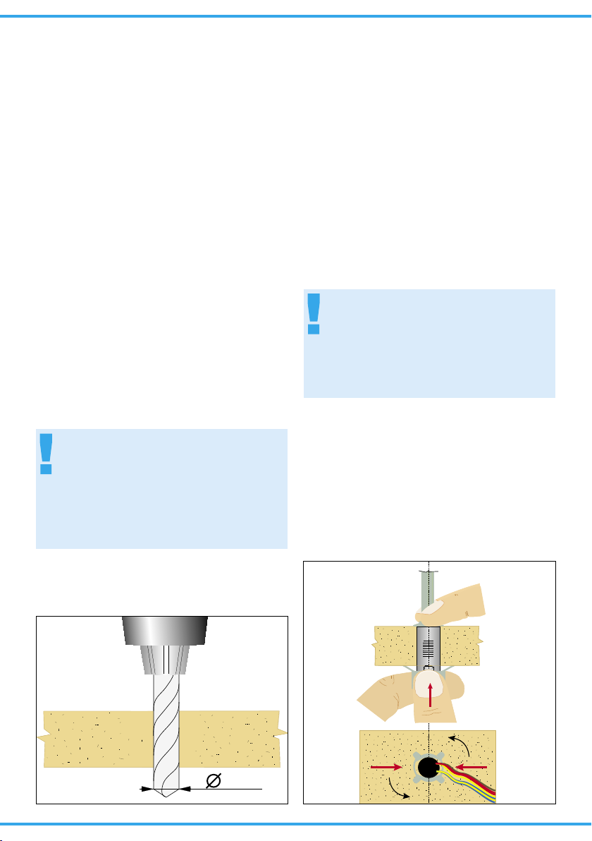
5. Montage
1. Beschriften Sie das Signal (siehe Kapitel 3).
2. Bohren Sie an der Montagestelle ein Loch mit
einem Durchmesser von 13 mm (Abb. 3).
Einen passenden Bohrer bietet Viessmann
unter Artikelnummer 7801 ebenfalls an.
3. Führen Sie die Anschlusskabel von oben durch
das Montageloch und stecken Sie dann das Signal mit dem Antrieb voran hinein.
4. Befestigen Sie das Signal mit dem beiliegenden Befestigungsring. Führen Sie dazu alle
Kabel des Signals durch den Ring. Die Federn
des Rings müssen in Richtung des Signals zeigen (Abb. 4).
Halten Sie das Signal am Sockel fest.
Schieben Sie den Ring über den Antrieb und
drücken Sie ihn gegen die Modellbahnplatte.
Drehen Sie den Ring um 90° um ihn zu arretieren
6. Anschluss
Alle Anschluss- und Montagearbeiten dürfen
nur bei abgeschalteter Betriebsspannung
durchgeführt werden!
Verwenden Sie nur nach VDE /EN-gefertigte
Modellbahntransformatoren!
Sichern Sie die Stromquellen unbedingt so
ab, dass es bei einem Kurzschluss nicht
zum Kabelbrand kommen kann.
Die Betriebsspannung beträgt 16 V = / ~.
5. Mounting
1) Check that the signal works properly as per the
instructions above before you start installing it
on the layout.
2) Letter the signal in accordance with the instructions on page 3.
3) Drill a hole of 13 mm diameter at the mounting
place (Fig. 3).
4) Insert the signal‘s connection wires into the
hole first. Then put the signal with the drive first
into the hole.
5) Attach the signal to the baseboard with the enclosed ring. Put the ring over the cables and
the drive unit of the signal (Fig. 4).
Turn the ring 90° to arret it.
6. Connections
Make sure that the power supply is switched
off when you mount the device and connect
the wires!
Only use VDE/EN tested special model train
transformers for the power supply!
The power sources must be protected to prevent the risk of burning wires.
The operating voltage is 16 V (AC/DC).
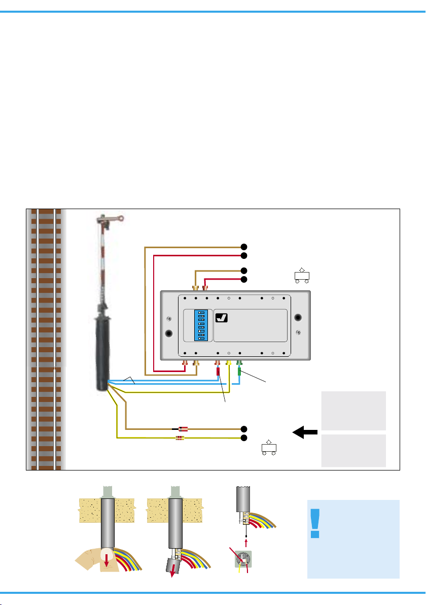
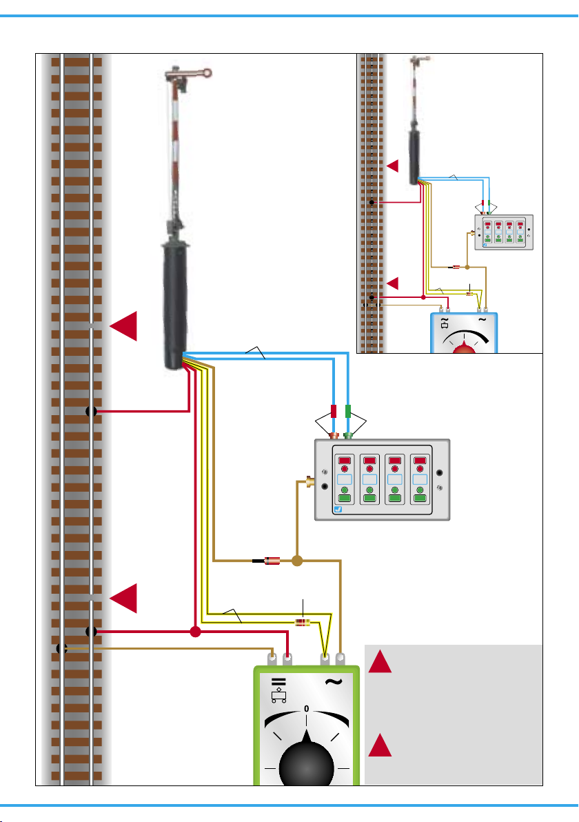
Now make the electrical connection as per figure
5 or 7. For the meaning of the cable colours refer
to figure 4
Page 5

5
blau mit roter Markierung
blue with red marking
blau mit grüner Markierung
blue with green marking
gelb + Widerstand / Markierung
yellow with resistor or marker
gelb
yellow
braun (+Diode bei LED-Licht)
brown (+diode for LED lighting)
rot
red
rot
red
Signal Hp0 (Halt)
Signal Hp0 (Stop)
Signal Hp1 (Fahrt)
Signal Hp1 (Proceed)
gemeinsamer Mittelpunkt der Antriebsspulen
common pole for the drive coils
Licht
Light
Licht (Masse)
Light (ground)
Kontakt für Zugbeeinflussung
contact for train control
Kontakt für Zugbeeinflussung
contact for train control
Abb. 5
Fig. 5
Schließen Sie nun das Signal gemäß den Abbildungen 6 oder 8 an. Zur Bedeutung der Kabelfarben siehe Abbildung 5.
Für die Versorgung der Signalbeleuchtung empfehlen wir einen separaten Transformator. Das
verhindert ein eventuelles Flackern der Beleuchtung beim Umschalten des Signales durch den erhöhten Strombedarf des Antriebes.
Gleichstrombetrieb: Schließen Sie die beiden
gelben Kabel an den Minuspol des Trafos an.
Analoge Ansteuerung
In Abbildung 8 zeigen wir Ihnen, wie einfach Sie
die zweibegriffigen Formsignale mit Hilfe der
Viessmann Tastenstellpulte 5547 (ohne Rückmeldung) oder 5549 (mit Rückmeldung durch LEDs)
anschließen können. Schalter, Taster und Relais
anderer Hersteller können Sie natürlich auch verwenden.
Digitale Ansteuerung
Viessmann-Formsignale können auch von einem
Digitalsystem angesteuert werden (Abb. 6). Beim
Anschluss z. B. an den Viessmann-Magnetartikel-Decoder 5211 (Märklin / Motorola) müssen Sie
darauf achten, dass neben den blauen Kabeln zur
Signalsteuerung auch das gelbe Kabel (ohne Markierung) für die Stromversorgung angeschlossen
ist. Zum digitalen Schalten eines zweibegriffigen
Signals wird eine Ausgangsgruppe eines Magnetartikeldecoders benötigt.
As a supply for the signal light, we recommend a
separate transformer. This will prevent flickering of
the lights due to high consumption of the drive.
Connect the signal light to the transformer via the
yellow cable with black marking and the brown
cable with the diode.
Direct current: Connect both yellow cables to the
negative pole of the transfomer.
Analogue Wiring
The conventional wiring is shown in figure 8. It
shows how you can connect the three-aspect
form signals to a push-button panel (e. g. 5547 or
5549).
Power is supplied via the brown wire and the two
yellow wires. The blue wires with the coloured
markings are connected to contacts (single momentary switches, track contacts, automatic track
switches, control panel), which in turn are wired to
the brown lead ( = “ground”). Never supply power
to more than one blue wire at the same time.
The red wires are used to connect the insulated
track section to the signal contacts (train control).
Digital Control
The semaphore signals can also be operated with
a digital system. Refer to figure 6 on the following
page for the correct wiring.
Simply connect the wires to a digital decoder (e.g.
Viessmann 5211 for Märklin / Motorola format.
Page 6
6
Fig. 7
Abb. 7
Nadel oder
dünner Draht
Needle or
thin wire
Diese Maßnahme
darf nur im stromlosen Zustand ausgeführt werden!
Switch off power
before doing this!
1. 2. 3.
rt bn rt 1 gn rt 2 gn
ON
1
2
3
4
5
6
7
8
WP
Viessmann
5211
Magnetartikeldecoder
rt bn E gn 4 rt gn 3 rt
braun
grün
rot
blau
gelb
z. B. 5211
Diode
Widerstand
Digitalzentrale
Optional:
separater
Anschluss des
Lichtstroms.
16 V ~ / =
gelb
16 V ~ / =
brown
green
red
blue
yellow
e. g. 5211
diode
resistor
Digital Command Station
Option:
separate power
supply for lights
yellow
Fig. 6
Abb. 6
Viessmann-Formsignale benötigen positive
Schaltimpulse. Daher kann man die Signale
nicht ohne weiteres mit allen Magnetartikeldecodern (z. B. von Lenz, Trix etc.) schalten, da diese Decoder negative Schaltimpulse liefern. Von
Viessmann gibt es daher für alle Digitalsysteme
Decoder, welche positive Schaltimpulse liefern!
Der 5211 (4-fach) ist kompatibel zum Märklin / Motorola und Märklin-Systems-Format. Der 5212
(4-fach) ist kompatibel zu allen DCC-Digitalsystemen wie z. B. Digital plus (Lenz), Arnold Digital,
Roco Digital, Fleischmann Twin Center, Digitrax,
Uhlenbrock Intellibox, Tillig Digital usw. . Der 5260
(8-fach) ist kompatibel zum SELECTRIX®-System
(mit Sx-Bus-Anschluss).
5212 is suitable for the NMRA DCC format or
5260 for SELECTRIX®).
Viessmann-semaphores need positive switching
impulses. Therefore you cannot use any decoder
(e. g. by Lenz, Trix etc.) because they use negative impulses.
Viessmann delivers decoders for all digital systems and standards:
5211: compatible with the Märklin / Motorola and
Märklin-Systems format.
5212: compatible with all DCC-systems e. g.
Digital plus (Lenz), Arnold Digital, Roco Digital,
Fleischmann Twin Center, Digitrax, Uhlenbrock
Intellibox, Tillig Digital etc.
5260: compatible with the SELECTRIX®-System
with Sx-Bus.
Page 7
7
Universal Tasten - Stellpult
5549
Viessmann
braun
brown
grün
green
rot
red
braun
brown
blau
blue
rot
red
rot
red
braun
brown
gelb
yellow
z. B. 5549
Diode
diode
Widerstand
resistor
e. g. 5549
Fig. 8
Abb. 8
System
Märklin H0
Beachten Sie die
Anschlusshinweise in
Kap. 6, S. 5
Note the connecting
instructions in chap. 6
on p. 5
Dieses Symbol neben dem
Gleis kennzeichnet eine
Trennstelle (Gleichstrom =
rechte Schiene in Fahrtrichtung, Wechselstrom = Mittelleiter).
This sign beside the track indicates a track insulation (DC
= right rail in driving direction,
AC = third rail).
Formsignal
mit einem Antrieb.
Semaphore Signal
with one drive unit.
16 V
Universal Tasten - Stellpult
5549
Viessmann
braun
brown
grün
green
rot
red
braun
brown
blau
blue
rot
red
rot
red
braun
brown
gelb
yellow
z. B.
5549
Diode
diode
Widerstand
resistor
16 V
Page 8

Dieses Produkt ist kein Spielzeug. Nicht geeignet für
Kinder unter 14 Jahren! Anleitung aufbewahren!
This product is not a toy. Not suitable for children
under 14 years! Keep these instructions!
Ce produit n’est pas un jouet. Ne convient pas aux
enfants de moins de 14 ans ! Conservez ce mode
d’emploi !
Dit produkt is geen speelgoed. Niet geschikt voor kinderen onder 14 jaar! Gebruiksaanwijzing bewaren!
Questo prodotto non è un giocattolo. Non adatto a
bambini al di sotto dei 14 anni! Conservare instruzioni per l’uso!
Esto no es un juguete. No recomendado para menores
de 14 años! Conserva las instrucciones de servicio!
8
08/2006 Bau
Stand 03
Sach-Nr. 98477
Made in Europe
02/2007 Ko
Stand 03
Sach-Nr. 98123
Made in Europe
8. Technical Data
Operating voltage: 16 V AC/DC
Peak inrush current (for approx. 0.1 s): 0.7 A
Max. contact load of
the track control contact: 2 A
8. Technische Daten
Betriebsspannung: 16 V =/~
Stromaufnahme
(im Schaltmoment, ca. 0,1 s): 0,7 A
Maximale Belastbarkeit
des Fahrstromkontaktes: 2 A
7. Fehlersuche
Jedes Viessmann-Produkt wird unter hohen Qualitätsstandards gefertigt und vor seiner Auslieferung geprüft. Sollte es dennoch zu einer Störung
kommen, können Sie anhand der folgenden Punkte eine erste Überprüfung vornehmen. Testen Sie
jedoch zuvor die Stromzuführungen.
1. Die Flügel stehen nicht gerade:
Signal auf Stellung „Halt“ (Hp0) stellen und Flü-
gel vorsichtig gerade stellen. Jeder Flügel lässt
sich auf seiner Drehachse verstellen. Unter
Umständen müssen Sie die auf der Rückseite
befindlichen Anschläge etwas nachrichten.
2. Das Signal schaltet hörbar, die Flügel bewegen sich jedoch nicht oder nur teilweise:
Hubstangen vorsichtig etwas nach oben oder
unten bewegen. Eventuell die Hubstangen
oben lösen und prüfen, ob die Flügelmechaniken sich widerstandslos bewegen lassen.
3. Die Signallampen leuchten, die Stromzuführung ist zweifelsfrei in Ordnung, das Signal
schaltet aber nicht:
Der innenliegende Richtungsumschalter hat
möglicherweise keinen Kontakt. Abhilfe: Strom
abschalten! Schutzkappe unten am Signalantrieb abziehen und den Schaltkontakt mit Hilfe
einer Stecknadel oder eines dünnen Drahtes
einmal nach oben bewegen (Fig. 6).
Sollte das Produkt beschädigt sein, geben Sie es
in der zugehörigen Verpackung zu Ihrem Fachhändler oder senden Sie es direkt an den
Viessmann-Service (Adresse siehe unten).
7. Troubleshooting
Every Viessmann-product is manufactured under
high quality standards and is tested before delivery. If there is a fault nevertheless, you can do a
first check. At first check the power supply.
1. The arms are not straight:
Set the signal to the Hp0 aspect (Stop) and adjust the arm back to the straight position very
careful! The bar can be shifted on its axle.
2. The switch sound of the signal drive can be
heard, but the arm doesn‘t move or moves
only a little bit.
Move the lifting rod very carefully a bit up and
down (if necessary detach the lifting rod from
the bar lever and check if bar mechanics can
be moved without resistance).
3. The signal lamp lights and the power supply
doubtless is in good order, however the signal doesn‘t switch.
Possible reason: The inner limit switch hasn‘t
got any contact.
Switch off the electrical power!! Than move up
the switch contact by means of a pin or a thin
wire (refer to figure 6).
If the product is damaged, send it in the original
package directly for repair to your local dealer or
to the Viessmann company (see below for address).
 Loading...