

Page 1
Bedienungsanleitung
Innovation,
AC
~
DC
=
DCC
Operation Manual
4570
Motorischer Türantrieb
mit Figurenbewegung
Motor door drive with
figure movement
1. Wichtige Hinweise / Important information ........................................................ 2
2. Einleitung / Introduction ..................................................................................... 3
3. Einbau / Mounting ............................................................................................. 4
4. Anschluss und Betrieb / Connection and operation .......................................... 7
5. Wartung / Maintenance ..................................................................................... 16
6. Fehlersuche und Abhilfe / Trouble-shooting ...................................................... 16
7. Technische Daten / Technical data .................................................................... 17
8. CV-Tabelle / CV table ........................................................................................ 18
MM
Rail
Com
die bewegt!
Page 2
DE EN
1. Wichtige Hinweise
Bitte lesen Sie vor der ersten Anwendung des Produktes
bzw. dessen Einbau diese Bedienungsanleitung aufmerksam durch. Bewahren Sie diese auf, sie ist Teil des
Produktes.
1.1 Sicherheitshinweise
Vorsicht:
Verletzungsgefahr!
Aufgrund der detaillierten Abbildung des Originals bzw.
der vorgesehenen Verwendung kann das Produkt Spitzen, Kanten und abbruchgefährdete Teile aufweisen. Für
die Montage sind Werkzeuge nötig.
Stromschlaggefahr!
Die Anschlussdrähte niemals in eine Steckdose einführen! Verwendetes Versorgungsgerät (Transformator,
Netzteil) regelmäßig auf Schäden überprüfen. Bei Schäden am Versorgungsgerät dieses keinesfalls benutzen!
Alle Anschluss- und Montagearbeiten nur bei abgeschal
teter Betriebsspannung durchführen!
Ausschließlich nach VDE/EN gefertigte Modellbahntransformatoren verwenden!
Stromquellen unbedingt so absichern, dass es bei einem
Kurzschluss nicht zum Kabelbrand kommen kann.
Zerstörungsgefahr!
Der Antrieb besteht aus einer empfindlichen Elektronikund Mechanikbaugruppe.
Öffnen sie die montierten Gehäuse unter keinen Umständen. Zerstörung des Antriebs oder Verletzungen
können die Folge sein.
1.2 Das Produkt richtig verwenden
Dieses Produkt ist bestimmt:
- Zum Einbau in Modelleisenbahnanlagen und Dioramen.
- Zum Anschluss an einen Modellbahntransformator
(z. B. Art. 5200) bzw. an eine Modellbahnsteuerung mit
zugelassener Betriebsspannung.
- Zum Betrieb in trockenen Räumen.
Jeder darüber hinausgehende Gebrauch gilt als nicht bestimmungsgemäß. Für daraus resultierende Schäden haftet
der Hersteller nicht.
1.3 Packungsinhalt überprüfen
Kontrollieren Sie den Lieferumfang auf Vollständigkeit:
- Motorischer Türantrieb mit Decoder inklusive Anschlusskabel und am Kabel befestigtem Vorwiderstand (1)
- Rechte Türaufnahme (2)
- Linke Türaufnahme (3)
- Untere Abschlussplatte (4)
- 2 Schrauben (5)
- Anleitung
Hinweis:
Tür und Figur sind nicht im Lieferumfang enthalten.
2
1. Important information
Please read this manual completely and attentively before
using the product for the first time. Keep this manual. It is
part of the product.
1.1 Safety instructions
Caution:
Risk of injury!
Due to the detailed reproduction of the original and the
intended use, this product can have peaks, edges and
breakable parts. Tools are required for installation.
Electrical hazard!
Never put the connecting wires into a power socket!
Regularly examine the transformer for damage. In case
of any damage, do not use the transformer.
Make sure that the power supply is switched off when
you mount the device and connect the cables!
-
Only use VDE/EN tested special model train transformers for the power supply!
The power sources must be protected to avoid the risk
of burning cables.
Risk of destruction!
The drive contains very sensitive mechanical and electronical components.
Never open the back cover of the drive. That may result
in destruction of the motor or injury.
1.2 Using the product for its correct purpose
This product is intended:
- For installation in model train layouts and dioramas.
- For connection to an authorized model train transformer
(e. g. item 5200) or a digital command station.
- For operation in dry rooms only.
Using the product for any other purpose is not approved
and is considered inappropriate. The manufacturer is not
responsible for any damage resulting from the improper
use of this product.
1.3 Checking the package contents
Check the contents of the package for completeness:
- Motor door drive with decoder, including connection
cables with serial resistor (1)
- Revolving door carrier, right (2)
- Revolving door carrier, left (3)
- Lower end plate (4)
- 2 screws (5)
- Manual
Notice:
Door and figure are not included in the scope.
Page 3
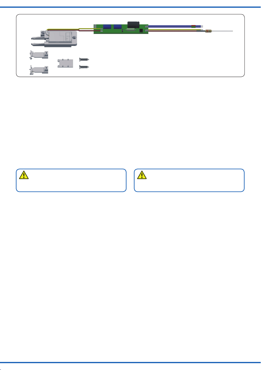
Abb. 1
Packungsinhalt / Package contents
1
2
5
3
4
Fig. 1
2. Einleitung
2.1 Funktionsumfang
Der Viessmann Türantrieb ist ein spezieller einflügeliger
Antrieb mit zugehörigem Digitaldecoder zum Einbau in
Modellhäuser für die vorbildgerechte Bewegung von einflügeligen Türen. Auf der Figurenplatte kann eine Figur
befestigt werden. Die Platte wird beim Öffnen der Tür nach
vorne geschoben. So entsteht der Eindruck, die Figur würde aus dem Haus heraustreten.
Geschwindigkeit und Bewegungsablauf sind elektronisch
gesteuert, wodurch ein feinfühliger Antrieb gewährleistet
ist. Schaltausgänge ermöglichen den Anschluss einiger
LEDs oder geeigneter Relais zur Beleuchtungssteuerung
im Modellhaus. Somit kann eine Anwesenheitssimulation
erzeugt werden.
Hinweis:
Der Antrieb kann nicht manuell verstellt werden. Der
Betrieb ist nur elektrisch möglich.
Der zugehörige Decoder versteht die Formate MärklinMotorola sowie DCC und kann die angeforderte Sollstellung oder Ist-Stellung per RailCom an geeignete Digitalzentralen zurückmelden. Zusätzliche Schaltausgänge für
konventionelle Stellungsrückmeldungen vervollständigen
den Funktionsumfang. Deren Funktion ist konfigurierbar.
2.2 Geeignete Spurgrößen
Der Antrieb kann zur Bewegung von Türen und Figuren in
den Massstäben 0, H0 und TT benutzt werden.
2.3 Ansteuerung im Digitalbetrieb
Der Türantrieb enthält einen Multiprotokoll-Decoder, der
entweder Signale im DCC-Format oder im Motorola-Format
auswertet. Welches Datenformat der Decoder auswertet,
wird bei der Einstellung der Digitaladresse festgelegt. Der
Antrieb ist ab Werk auf die DCC-Adresse 1 eingestellt.
Der Adressumfang ist von Format abhängig, mit dem der
Decoder angesteuert wird.
Motorola-Format: 320 (1020 bei entsprechender
Zentrale) Adressen.
DCC- Format: 2047 Adressen.
2.4 Ansteuerung im Analogbetrieb
Der Viessmann Türantrieb kann auch in konventionell
gesteuerten Modellbahnanlagen eingesetzen werden.
Ein Betrieb mit Wechselstrom als auch mit Gleichstrom
ist möglich.
2. Introduction
2.1 Functions
The Viessmann door drive is a special one-wing drive with
its corresponding digital decoder. It is intended for installation in model houses for the prototypical movement of
one-wing doors. A figure can be mounted onto the figure
plate. When opening the door, the plate is being pushed
forward thus creating the impression of the figure leaving
the house.
Speed and movement coordination are controlled electronically which ensures a smooth drive. Switching outputs
allow the connection of several LEDs or appropriate relays
for lighting control in the model house. Thus you can simulate the presence of residents.
Notice:
The drive cannot be set manually. Operation with electricity only.
The associated decoder is suitable for DC/AC, MM and
DCC and is able to answer requests for the required or
actual position by RailCom to appropriate digital command
stations. Additional switching outputs for a conventional
feedback complete the functions. Their function is configurable.
2.2 Compatible track gauges
The drive can be used for the movement of doors and
figures in gauges 0, H0 and TT.
2.3 Operation in digital mode
The door drive contains a multiprotocol decoder analysing
signals either in DCC or Motorola format. The data format
is selected when setting the digital address. The ex works
DCC address for the drive is 1.
The address volume depends on the format used for controlling the decoder.
Motorola format: 320 addresses (1020 with appropriate
command station).
DCC format: 2047 addresses.
2.4 Operation in analogue mode
The Viessmann door drive can be used in conventional
model train layouts. You may use AC or DC power supply
for operation.
3
Page 4
Sobald der Antrieb an die Betriebsspannung angeschlossen ist, erkennt der integrierte Decoder automatisch, ob er
analog oder digital angesteuert wird und stellt den entsprechenden Betriebsmodus ein.
2.5 Verhalten bei Überlastung
Bei mechanischer Überlastung schaltet der Überlastschutz
den Antrieb automatisch zeitverzögert ab.
2.6 Rückmeldung mit RailCom
RailCom ist ein Zusatzprotokoll zur bidirektionalen
Kommunikation in digitalen Modellbahnanlagen, die im
DCC-Format gesteuert werden. Es ermöglicht z. B. die
Stellungsrückmeldung des Antriebs zur Digitalzentrale.
Das Versenden von RailCom-Messages ist nur in Anlagen möglich, in denen ein DCC-Signal an den Schienen
anliegt und seitens der Zentrale bzw. der Booster eine
entsprechende Austastlücke im Datenstrom erzeugt wird.
Daher ist die Nutzung der RailCom-Funktion in einer
reinen Motorola-Umgebung nicht möglich.
Sofern der Decoder im Türantrieb die Austastlücke registriert, sendet er nach einem erhaltenen Schaltbefehl als
Quittung die Soll-Stellung und Ist-Stellung des Antriebs
zurück. Bei drehendem Motor wird die geschätzte übrige
Zeit zurückgegeben, bis der Motor zum Stehen kommt.
Once the drive is connected to the operating voltage, the
integrated decoder recognizes automatically if it is approached in an analogous or digital way and switches to
the corresponding operating mode.
2.5 Overload protection
If the door drive recognizes a mechanical overload, it switches
off after a short time to protect itself against destruction.
2.6 Feedback with RailCom
RailCom is an additional protocol for bi-directional communication in digital model train layouts controlled in DCC.
It allows e. g. the drive to give a position feedback to the
digital command station.
Sending RailCom messages is only possible in layouts with a DCC signal on the rails and if the command
station and/or the booster(s) generate a cut-out in the digital signal. That is why it is not possible to use RailCom in
a Motorola system without DCC.
Whenever the decoder inside the door drive registers the
RailCom cut-out, it answers the switching commands with
both the required and the actual position of the drive. In
case of a moving motor, the estimated remaining movement time is reported.
3. Einbau
Vorsicht:
Sowohl mechanische als auch elektronische Bauteile
im Inneren des Türantriebs und des Decoders sind sehr
empfindlich. Arbeiten Sie also sehr vorsichtig!
Alle Anschluss- und Montagearbeiten dürfen nur bei
abgeschalteter Betriebsspannung durchgeführt werden.
3.1 Allgemeine Hinweise
Das Gehäuse ist systembedingt nicht hermetisch versiegelt. Durch die Öffnungen im Gehäuse können Kleinteile
wie Streumaterial etc. ins Innere gelangen und den Antrieb
zerstören.
Hinweis:
Achten Sie bei der Montage auf der Grundplatte
darauf, dass die Oberfläche eben und sauber ist.
Unter dem Türantrieb darf kein Streumaterial (Steine,
Schotter etc.) verwendet werden. Ansonsten können
Getriebegehäuse und Mechanik verformt und zerstört
werden.
3.2 Türantrieb vorbereiten
Der Türantrieb kann in Modellhäusern eingebaut werden,
deren Türöffnung (Türbreite) min. 10 mm ist. Er lässt sich
am einfachsten in Modellhäusern montieren, die mit der
Modellbahnanlage noch nicht fest verbunden sind und
deren Dach noch nicht geklebt ist. In diesem Zustand können die Türöffnungen mühelos aus den Modellhäusern
ausgeschnitten werden.
Mit dem Antrieb kann eine bis zu 135° betragende Öffnung
der Tür und eine Figurenbewegung von 10 mm erreicht
werden.
4
3. Mounting
Caution:
Be careful with the door drive. Mechanical as well as
electronical components in the device itself and the
decoder are very sensitive.
Make sure that the power supply is switched off when
you mount the device and connect the cables!
3.1 General information
For systemic reasons, the housing is not hermetically
sealed. Small parts like ballast etc. may penetrate the
housing through the openings and destroy the door drive!
Notice:
When mounting the door drive, the ground plate has to
be even and clean.
Underneath the door drive there must not be any material like ballast etc. Otherwise the housing and the
mechanical parts can be deformed and destroyed.
3.2 Prepare door drive
The door drive can be installed in model houses with a
door opening (door width) of min. 10 mm. The mounting
becomes easier if the model houses are not yet attached
to the layout and if the roof has not been fastened with
glue. In this state, the door openings can effortlessly be
cut out of the model houses.
The door drive can achieve a 135° opening of the door and
a figure movement of 10 mm.
Page 5
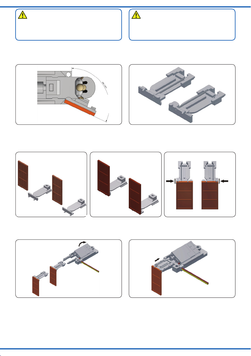
Achtung:
Für eine einwandfreie Funktion des Antriebes muss
sichergestellt werden, dass der Türträger mit der verklebten Tür um mindestens 115° geöffnet werden kann!
(Abb. 2)
Um die maximale Öffnung zu erreichen, dürfen keine Hindernisse im Weg der zu öffnenden Tür sein.
Es ist günstig, so dünne Türen wie möglich zu verwenden
Die ideale Dicke ist 1 mm.
Abb. 2
Drehpunkt
pivotal point
x
Fig. 2
Rechts
angeschlagen
(R)
right hinged
(R)
Wählen Sie die entsprechenden Türaufnahmen: Tür und
Figur: „Rechts“ (R) oder „Links“ (L) (Abb. 2.1).
Kleben Sie die Tür an den Türhalter, so dass die beiden
Teile am Drehpunkt bündig zueinander sind (Abb. 2.2, Abb.
2.3, Abb. 2.4).
Abb. 2.2 Abb. 2.4Abb. 2.3
Rechts
angeschlagen
(R)
right hinged
(R)
Teil 2
part 2
Fig. 2.2 Fig. 2.4Fig. 2.3
Links
angeschlagen
(L)
left hinged (L)
Attention:
For a trouble-free operation of the drive, it has to be
made sure that the door carrier with the adherent door
can be opened by at least 115°! (fig. 2)
In order to achieve the maximal opening, the way of the
opening door must be free from any obstacles.
It is advisable to use as thin doors as possible. The ideal
thickness is 1 mm.
Abb. 2.1
Links
angeschlagen
(L)
left hinged (L)
Rechts angeschlagen (R)
oder/or
right hinged (R)
Fig. 2.1
Choose the appropriate door carriers: door and figure:
“Right” (R) or “Left” (L) (fig. 2.1).
Stick the door to the door carrier so that both parts are
flush fitting at the pivotal point (fig. 2.2, fig. 2.3, fig. 2.4).
Teil 3
part 3
Kippen Sie den Antrieb leicht aus seiner Halterung (Abb.
2.5).
Slightly incline the drive out of its fitting (fig. 2.5).
Push the door carrier (2) or (3) into its place (fig. 2.6).
Schieben Sie die Türaufnahme (2) oder (3) an ihren Platz
(Abb. 2.6).
Abb. 2.5 Abb. 2.6
Kippen Sie den Antrieb zurück, so dass der Schieber des
Antriebs mit der Türaufnahme verbunden werden kann
(Abb. 2.7).
Bei der Montage der Abschlussplatte müssen die kleinen
Positionierungsstifte an der Platte in die vorgesehenen
Bohrungen einrasten. Achten sie darauf, dass der Füh-
Fig. 2.5 Fig. 2.6
Move the drive back so that its pusher can be connected
with the door carrier (fig. 2.7).
When mounting the end plate, the small positioning bolts
at the plate have to lock in with the designated bores.
Make sure that the guiding pin is positioned correctly in
the door carrier bore (fig. 2.8).
rungszapfen korrekt in der Bohrung der Türhalterung
positioniert ist (Abb 2.8).
5
Page 6
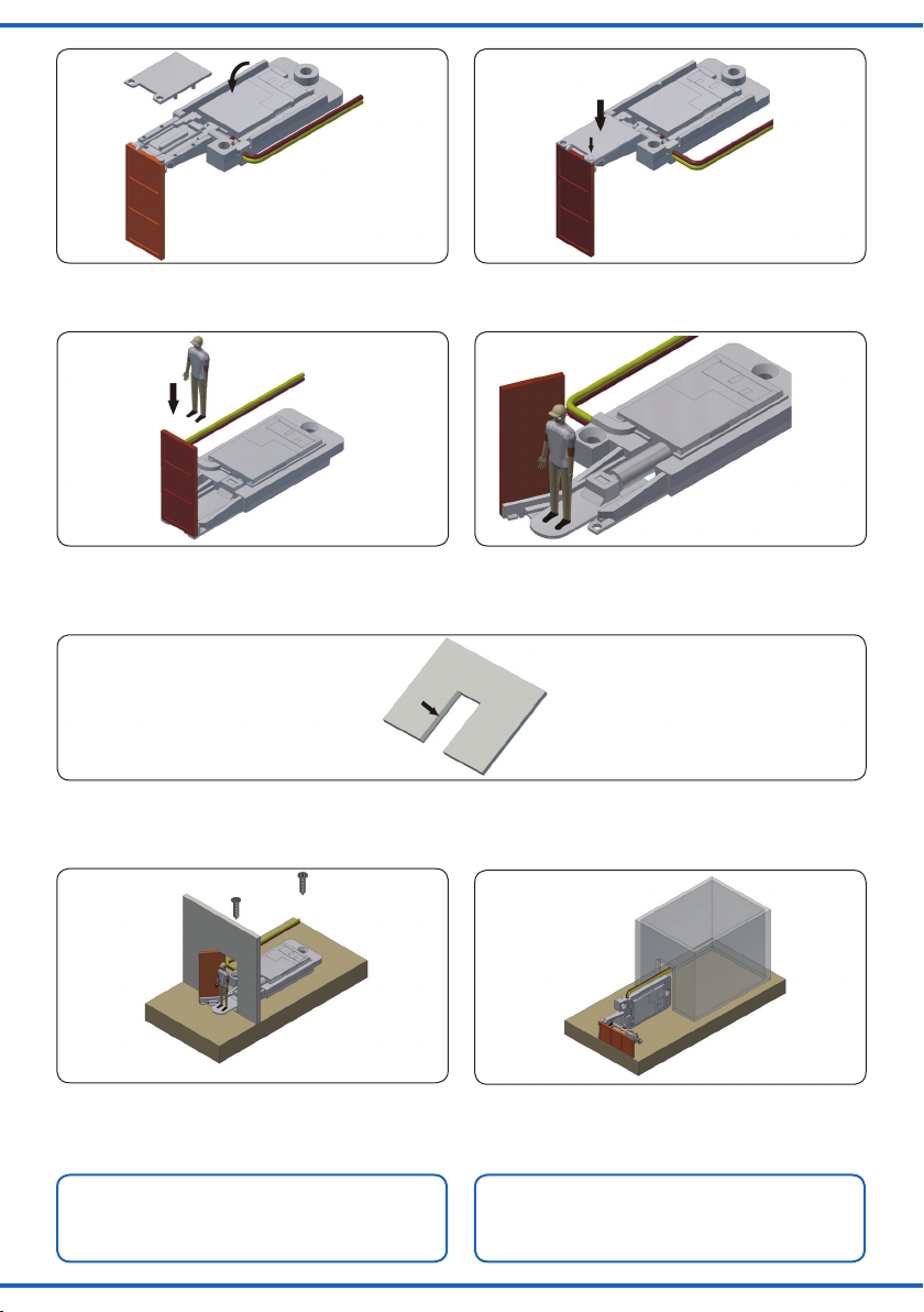
Abb. 2.7
Fig. 2.7
Abb. 2.8
Fig. 2.8
Ein Anbringen der Figur ist jetzt bei geschlossener Tür
möglich. Achtung: die Breite der Figur ist durch die Türöffnung begrenzt (Abb. 2.9, Abb. 2.10).
Abb. 2.9
Fig. 2.9
3.3 Einbau in das Modellhaus
Den Türpfosten an der Seite, an der sich die Türdrehachse
befindet, ggf. mit einer Feile so bearbeiten, dass die Tür so
weit wie möglich geöffnet werden kann (Abb. 3).
Abb. 3
Setzen Sie den Antrieb an die vorgesehene Stelle des
Modellhaus und deren Türöffnung (Abb. 3.1).
Befestigen Sie den Antrieb mit den beiliegenden Schrauben
(5) (Abb. 3.1).
Abb. 3.1
Fig. 3.1
At this stage it is possible to mount the figure when the
door is closed. Attention: The width of the figure is limited
by the door opening (fig. 2.9, fig. 2.10).
Abb. 2.10
Fig. 2.10
3.3 Mounting in the model house
Where necessary, work the door post at the side of the pivotal point with a file in a way that the door can be opened
as wide as possible (fig. 3).
Fig. 3
Position the drive at the designated spot of your model
house and its respective door opening (fig. 3.1).
Fasten the drive with the enclosed screws (5) (fig. 3.1).
Abb. 3.2
Fig. 3.2
Tipp:
Bei einem eingebauten Modellhaus können Sie den
Antrieb notfalls auch durch die Türöffnung installieren
(Abb. 3.2, Abb. 3.3, Abb. 3.4).
6
Hint:
If the model house is already mounted, you can install
the drive also through the door opening, if necessary
(fig. 3.2, fig. 3.3, fig. 3.4).
Page 7

Abb. 3.3 Abb. 3.4
rot
Fig. 3.3 Fig. 3.4
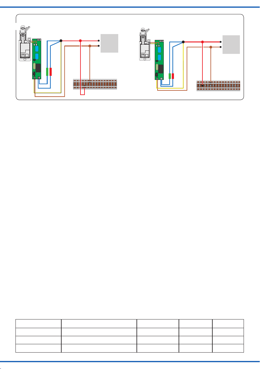
4. Anschluss und Betrieb
Für eine schnelle Inbetriebnahme verbinden Sie den
Antrieb entweder nach Abb. 4 für den Analogbetrieb oder
nach Abb. 5 für den Digitalbetrieb. Wenn Sie das MotorolaProtokoll verwenden, müssen Sie den Antrieb zunächst
gemäß Kapitel 4.6 auf Motorola umstellen.
Für den Betrieb drücken Sie die entsprechende Taste auf
dem Tastenstellpult (konventioneller Betrieb) oder senden
Sie einen entsprechenden Befehl an die Adresse des
Türantriebs (digitaler Betrieb). Der Türantrieb öffnet die
Tür vorbildgerecht langsam. Dies dauert etwa 2,5 Sek..
Während der Stellzeit speichert der Antrieb einen weiteren
Befehl der eine andere als die aktuelle Stellung bedeutet
und führt diesen nach einer kurzen Kühlzeit (ca. 0,5 Sek.)
aus.
Abb. 4
Universal Tasten - Stellpult
5200
Lichttransformator
Primär
230 V~
Primär 230 V 50 - 60 Hz
Sekundär max. 3,25 A52 VA
Nur für trockene Räume
4.1 Werkseinstellungen
Ab Werk ist der Decoder auf die Digitaladresse 1 (DCCProtokoll) eingestellt. Weitere Konfigurationsmöglichkeiten
entnehmen Sie bitte der beigelegten CV-Tabelle.
4.2 Konventioneller (analoger) Betrieb
Im konventionellen (analogen) Betrieb schalten Sie den
Türantrieb mit geeigneten Tastenstellpulten (z. B. Art.
5547). Schließen Sie den Türantrieb und das Tastenstellpult
wie in Abb. 4 gezeigt an. Verwenden Sie einen geeigneten
Transformator (z. B. Viessmann Art. 5200).
4.3 Digitalbetrieb
Dieser Decoder lässt sich als Schaltartikel ansteuern. Er
bietet aber auch den Komfort, auf einer Lokadresse angesteuert werden zu können. Dies kommt den Modellbahnern
/ red
grün
5547
5547
16 V
5200
10 V
Sekundär
0-10-16 V~
ta 25°CIP 40
0 V
Gefertigt nach
VDE 0570
EN 61558
4. Connection and operation
For a quick startup, connect the drive either acc. to fig. 4
for analogue mode or acc. to fig. 5 for digital mode. If you
use the Motorola protocol you have to start with adjusting
the drive to Motorola acc. to chapter 4.6.
For operation, press the respective button on the push
button panel (conventional mode) or send an appropriate
command to the address of the door drive (digital mode).
The door drive opens the door in a prototypically slow
way. This takes ca. 2.5 seconds. During the movement the
drive saves another command for a different position and
executes it after a short downtime (ca. 0.5 sec.).
/ green
4570
braun
brown
gelb
4.1 Default settings
The factory setting for the digital address is 1 (Motorola
format). Please find further configuration options in the
enclosed CV table.
4.2 Conventional (analogue) operation
In case that you use the door drive on conventional layouts,
use a push-button panel (e. g. item 5547). Connect the door
drive and the push-button panel as shown in fig. 4. Use a
suitable transformer (e. g. item 5200).
4.3 Digital operation
This decoder can be controlled as a switching decoder.
However, it also offers the option to be controlled with a
locomotive address. This is particularly useful for modellers
/ yellow
4570
grün
green
rot
/ red
Fig. 4
7
Page 8

Mot. / DCC
Motorola
DCC
4570
gelb
Digitalzentrale
braun
Adresse einstellen
grünes Kabel verbinden
rotes Kabel verbinden
rot /
red
grün
/ yellow
Digital command station
/ brown
/ set address
/ connect green cable
/ connect red cable
green
Abb. 5
Fig. 5
entgegen, deren Zentrale keinen bequemen Zugriff auf
Schaltartikel ermöglicht.
Im digitalen Betrieb schalten Sie den Türantrieb über eine
Digitalzentrale. Legen Sie als erstes eine Digitaladresse
fest (Abb. 5). Lesen Sie dazu die beiden folgenden Kapitel.
Nach Festlegung der Digitaladresse schließen Sie den
Türantrieb an (Abb. 6).
Wenn die Bewegungsrichtung nicht mit der Schaltrichtung
auf Ihrem Eingabegerät übereinstimmt, können Sie die
Stellrichtung des Antriebs umkehren. Schließen Sie nach der
Programmierung beide blauen Drähte gemeinsam an (Abb.
6.1): Bei Märklin/Motorola beide Drähte an den Mittelleiter; bei
DCC an eine beliebige der beiden Schienen. Alternativ können
Sie die Schaltrichtung in der CV 36 ändern.
Abb. 6
4570
red
rot /
grün / green
8
who do not have a command station with easy access to
switching items.
In the digital mode of operation, use a digital command
station to control the door drive. Select a digital address
first (fig. 5). Please read the following two chapters to learn
how to set a digital address.
After selection of the digital address, connect the door
drive (fig. 6).
If the properties of your drive do not correspond with the
switching direction specified by your input device, you have
the possibility to reverse its direction. After programming,
connect both blue wires together (fig. 6.1): In a Märklin/
Motorola system, connect both wires to the middle rail; for
DCC, connect both wires to any of the two rails. Alternatively,
switching direction can be changed in CV 36.
braungelb
brownyellow
rot
/ red
Digitalzentrale
Digital
command
station
braun
brown
Fig. 6
MM
Page 9
MM
Abb. 6.1
4570
Anschluss nach Adressprogrammierung für invertierte Stellrichtung!
Connection after programming the address for reverse switching direction!
grün / green
red
rot /
DCC
Digital-
/ red
rot
zentrale
Digital
command
braun
brown
station
braungelb
brownyellow
4570
grün / green
red
rot /
Fig. 6.1
Digital-
/ red
rot
zentrale
Digital
command
braun
brown
station
braungelb
brownyellow
4.4 Einrichtung mit DCC-Zentralen
Zur digitalen Steuerung des Türantriebs müssen Sie diesem zunächst eine Digitaladresse zuweisen. Zur Steuerung
im DCC-System gehen Sie wie folgt vor:
1. Schalten Sie das Digitalsystem aus, z. B. Not-Aus.
Es darf keine Spannung mehr am Gleis anliegen.
2. Verbinden Sie erst die rot markierte Steuerleitung und
die Stromversorgungsleitungen des Türantriebs (braun
und gelb, (Abb. 6)) mit dem Gleis.
3. Schalten Sie das Digitalsystem ein.
4. Verbinden Sie nun die (grün markierte) Steuerleitung
gleichfalls mit dem Gleis (Abb. 6.1).
5. Senden Sie mit der Digitalzentrale nun für die
gewünschte DCC-Adresse einen Schaltbefehl.
Der Türantrieb empfängt den Befehl, registriert die
Adresse und quittiert dies durch Umschalten.
Damit ist der Türantrieb unter der neuen Adresse
betriebsbereit. Falls Sie die Adresse künftig ändern möchten, wiederholen Sie die Prozedur einfach.
4.5 Programmieren am Programmiergleis
Die Konfiguration des Antriebs können Sie auch direkt am
Programmierausgang von Zentralen, die DCC-kompatibel
sind, vornehmen. Verbinden Sie dazu die Anschlüsse des
Türantriebs wie in Abb. 6 gezeigt mit dem Programmierausgang Ihrer Zentrale.
Die Adresse des Antriebs wird in zwei CVs programmiert.
In CV 1 steht das untere Byte (LSB) der Adresse, in CV 9
das obere Byte (MSB).
Das Umrechnen der Adresse geschieht wie im Folgenden
beschrieben. Wenn Sie eine Adresse zwischen 1 und 255
eingeben wollen, schreiben Sie diesen Wert direkt in CV 1.
Den Wert in CV 9 setzen Sie auf Null. Höhere Werte als
255 müssen aufgeteilt werden in MSB und LSB. Teilen Sie
die gewünschte Adresse durch 256 und ermitteln Sie das
ganzzahlige Ergebnis und den Rest.
Beispiele:
4. 4 Configuration with DCC command stations
To use the door drive in a digital environment, you have to
assign a digital address first. To control the door drive with
a DCC-system, follow the instructions below:
1. Switch off the digital system (e. g. emergency off).
There must not be any power at the rails.
2. Connect only the blue wire with the red marking and the
power supply wires of the door drive (brown and yellow,
fig. 6) to the rail.
3. Switch on the digital system.
4. Connect the second blue wire (green marked) to the
track signal, too (fig. 6.1).
5. Use the digital command station to send a switching
command for the desired DCC address. The door drive
receives the request, registers the address as its own
and as a receipt, it performs the switching.
The motor door is now ready to be used with the new digital address. Whenever you want to change the address,
you just have to repeat the described procedure.
4.5 Programming on the programming track
The configuration of the drive can also be accomplished
by connecting it directly to the programming output of the
command station. Simply connect the terminals of the
door drive to the programming output of the command station as shown in fig. 6.
The address of the drive is programmed in two CVs. In CV
1 you set the lower byte (LSB) of the address, in CV 9 the
upper byte (MSB).
The address is established as described below. Write
the address value directly into CV 1 if you wish to assign
an address between 1 and 255. Set CV 9 to 0. Higher
addresses than 255 must be split into the MSB and the
LSB. Divide the desired address by 256 and determine
the result without decimal points as well as the remainder.
Examples:
Adresse/Address ganzzahliges Ergebnis/Integer result Rest/remainder CV 9 = MSB CV 1 = LSB
256 1 0 1 0
911 3 911-256x3=143 3 143
1025 4 1025-256x4=1 4 1
9
Page 10

Die weiteren Einstellmöglichkeiten entnehmen Sie der CVTabelle. In CV 40 können Sie auch das Protokoll festlegen,
auf das der Türantrieb später „hört“.
Auf Befehle am Programmierausgang einer DCC-kompatiblen Zentrale hört der Decoder immer - unabhängig vom
eingestellten Protokoll.
4.6 Einrichtung mit Motorola-Zentralen
Damit Sie den Türantrieb digital ansteuern können, müssen Sie
diesem zunächst eine Digitaladresse zuweisen. Zur Steuerung
im Märklin-Motorola-System gehen Sie wie folgt vor:
1. Schalten Sie das Digitalsystem aus, z. B. Not-Aus. Es
darf keine Spannung mehr am Gleis anliegen.
2. Verbinden Sie nur die grün markierte Steuerleitung und
die Stromversorgungsleitungen des Türantriebs (braun
und gelb, Abb. 5) mit dem Gleis.
3. Schalten Sie das Digitalsystem ein.
4. Verbinden Sie die rot markierte Steuerleitung gleichfalls
mit dem Gleis (Abb. 6).
5. Senden Sie mit der Digitalzentrale nun für die gewünschte Motorola-Adresse einen Schaltbefehl. Der
Türantrieb empfängt den Befehl, registriert die Adresse
und quittiert dies durch Umschalten.
Damit ist der Türantrieb unter der neuen Adresse betriebsbereit. Falls Sie die Adresse künftig ändern möchten,
wiederholen Sie die Prozedur einfach.
Beachten Sie: Wenn Sie eine Zentrale einsetzen, die
sowohl das DCC- als auch das Motorola-Format sendet,
ist die Programmierung des Türantriebs im DCC-Format
empfehlenswert. Im Motorola-Format ist der Adressbereich
bei vielen Zentralen auf 320 Adressen beschränkt.
4.7 Digitalbetrieb auf einer Lokadresse
Um den Decoder auf eine Lokadresse zu programmieren,
gehen Sie wie folgt vor:
Bestimmen Sie, welches Digitalsystem verwendet werden
soll. Gehen Sie dazu vor, wie unter den Punkten 1 bis 4
bei „Einrichtung mit DCC-Zentralen“ oder „Einrichtung mit
Motorola-Zentralen“ beschrieben. Stellen Sie alle Lokomotiven auf Fahrstufe Null, sofern Ihre Zentrale dies nicht
automatisch tut.
An Punkt 5 senden Sie jedoch keinen Weichenschaltbefehl,
sondern einen Lok-Fahrbefehl auf der Adresse, die der
Antrieb bekommen soll. Betätigen Sie dazu den Fahrregler,
so dass eine Fahrstufe an die Adresse gesendet wird, die
nicht Null ist. Diese Adresse entspricht der Gruppenadresse
eines typischen 4-fach-Decoders. Auf dieser Lokadresse
wählen Sie dann eine Funktion F1 bis F4, die dadurch dem
Türantrieb zugeordnet wird. Somit können Sie 4 Türantriebe auf eine Lokadresse legen, analog zum 4-fach-Decoder.
Der Adressbereich ist auf 1 bis 99 begrenzt.
4.8 Programmieren mittels POM
Der Decoder lässt die Programmierung aller CVs per POM
(„Programming on the Main“, „Hauptgleisprogrammierung“)
zu. Nicht alle Zentralen unterstützen POM-Befehle an
Schaltartikel-Decodern. Deswegen kann man den Decoder auch auf Lokdecoder-POM Modus umstellen. Dies
geschieht dadurch, dass auf der Adresse 9999 der Wert
80 in die CV 8 geschrieben wird. Der Antriebsdecoder hört
dann auf normale POM-Befehle für Lokomotiven unter
seiner aktuellen Adresse.
10
Further programming options are listed in the CV table.
You may also set the desired digital protocol in CV 40.
The decoder will respond to commands of the programming output of a DCC compatible command station regardless of the set protocol.
4.6 Conguration with Motorola central units
To use the motor door in a digital environment, you have
to assign a digital address first. To control the motor door
with a Motorola system, observe the following instructions:
1. Switch off the digital system (e. g. emergency off). There
must not be any power at the rail.
2. Connect only the blue wire with the green marking and
the power supply wires of the motor door (brown and
yellow, fig. 5) to the rail.
3. Switch on the digital system.
4. Connect the second blue wire (red marked) to the track,
too (fig. 6).
5. Use the digital command station to send a switching
request for the desired Motorola address. The door drive
receives the request, registers the address as its own
and as a receipt, it performs the switching.
The door drive is now ready to be used with the new digital
address. If you want to change the address, you just have
to repeat the described procedure.
Notice: If you use a multi protocol digital command station, which is able to use the Motorola- as well as the DCCsystem simultaneously, it is recommended to programme
the door drive on a DCC address. When using Motorola
format, only 320 addresses may be provided.
4.7 Digital mode with a locomotive address
Proceed as follows if you wish to programme the decoder
to a locomotive address:
Decide which digital system you are going to use. Proceed
as described in points 1 - 4 in the chapter “Configuration
with DCC command stations” or “Configuration with Motorola central units”. Set all locomotives to speed step 0
if your command station does not do that automatically.
Instead of the point switching command as per point 5
send a locomotive driving command to the address to
be assigned to this drive. Turn up the throttle in order to
send a speed command greater than 0. This address
corresponds to the typical group address of an accessory
decoder with four double-outputs. Select one of the functions F1 to F4 of this locomotive address, which assigns
the functions of this address to the door drive. Thus you
may control four drives with one locomotive address similar to a fourfold decoder. The address range is limited to
addresses from 1 to 99.
4.8 Programming with POM
The decoder supports programming of all CVs per POM
(“Programming on the main”). Since not all command stations support POM for switching decoders you may also
set the decoder to respond to the locomotive POM mode.
Enter the value 80 in CV 8 of the address 9999. The drive
decoder will respond to normal POM commands for locomotives under the respective address.
Page 11

Beachten Sie, dass hier aus Sicherheitsgründen immer
zunächst CV 1 und dann CV 9 geschrieben werden muss,
auch dann, wenn sich der Inhalt von CV 9 nicht geändert
hat.
Hier ist also Vorsicht geboten, damit nicht gleichfalls Lokomotiven, die diese Adresse haben, umprogrammiert
werden. Gleichnamige Lokomotiven müssen entfernt oder
der entsprechende Stromkreis muss abgeschaltet werden.
Unter RailCom werden die entsprechenden Nachrichten an
die Zentrale gesendet.
4.9 Die Schaltausgänge
Die Schaltausgänge sind zugänglich an der Schmalseite
der Platine, an der auch die Motorkabel angeschlossen
sind. Die Schaltausgänge können auf verschiedene Funktionalitäten konfiguriert werden (CV 38). Sie sind vorgesehen
zum Schalten von Relais, können aber kleine Verbraucher
wie LEDs auch direkt schalten. Insbesondere eignen sie
sich zum Betreiben von LEDs, mit denen die Beleuchtung
eines Flures und eines Hauseingangs simuliert werden
kann. An den Ausgängen liegt ein positiver Schaltimpuls an.
4.10 Stellungsrückmeldung per Relais
Der Türantrieb verfügt über einen Transistor-Schaltausgang
zur Rückmeldung seiner Stellung. Er kann damit beispielsweise bistabile Relais schalten. Der Kontakt wird jeweils am
Ende des vorgesehenen Stellweges der Weiche für ca. 250
ms eingeschaltet. So können Sie z. B. den Zustand des
Antriebs an weitere Diorama-Elemente melden.
Aufgrund der geringen Belastbarkeit, der kurzen Schaltzeit
und zur Potentialtrennung nutzen Sie auf jeden Fall ein
Relais wie z. B. das Elektronische Relais Art. 5552 von
Viessmann. Zum Anschluss siehe Abb. 7.
For safety you should first edit CV 1 and then CV 9, even
if the value of CV 9 did not change.
Please be careful to avoid inadvertent programming of
other locomotives with the same address. Remove locomotives with the same address from the track or disconnect power to such track sections. If RailCom is active,
the corresponding feedback will be sent to the command
station.
4.9 Switching outputs
The switching outputs are accessible at the narrow side of
the circuit board to which also the motor cables are connected. The switching outputs can be configured to suit
various functionalities (CV 38). The outputs are intended for
relays, but can also power small loads such as LEDs.
They are particularly suitable for powering LEDs used to
simulate the lighting of a hallway and a house entrance.
The outputs hold a positive switching pulse.
4.10 Feedback via relays
The door drive is equipped with a transistor-driven output,
which is able to indicate its actual position. This output is
used to operate latching relays. The contact is turned on
for approx. 250 ms, when the drive reaches its respective
end position. With these contacts (soldering pads on the
back of the casing), you may feedback the position of the
point to a suitable control system. You can, e. g. report the
state of the drive to further diorama elements.
Due to the low power rating, the short switching time and
for isolation make sure to use a relay such as the Viessmann electronic relay item 5552. For connection, refer to
fig. 7.
Abb. 7
Schaltkontakte
(als Lötflächen ausgeführt)
Switching outputs
(soldering pads)
Max. Strom: 50 mA
Max. current: 50 mA
4570
3 x blau
Fig. 7
Elektr. Relais 5552
4570
/ blue
11
Page 12

external light
Abb. 8
Fig. 8
Schaltkontakte
4570
(als Lötflächen ausgeführt)
Switching outputs
(soldering pads)
Max. Strom: 50 mA
Max. current: 50 mA
4570
/ blue
3 x blau
CV für
inneres Licht
CV for interior lighting
121 (1) 131 (0) 0..1 Wie startet die Beleuchtung?
122 (0) 132 (0) 0..255 Zeit: Lichtwechsel bevor die Tür
123 (0) 133 (25) 0..255 Zeit: Lichtwechsel nachdem die Tür
124 (0) 134 (0) 0..255 Zeit: Lichtwechsel bevor die Tür
125 (1) 135 (50) 0..255 Zeit: Lichtwechsel nachdem die Tür
126 (0) 136 (0) 0..255 Wie CV 122/132 Same as CV 122/132
127 (50) 137 (1) 0..255 Wie CV 123/133 Same ad CV 123/133
128 (0) 138 (0) 0..255 Wie CV 124/134 Same ad CV 124/134
129 (0) 139 (50) 0..255 Wie CV 125/135 Same ad CV 125/135
Werte
values
CV für
außeres Licht
CV for external lighting
Werte
values
Wertebereich
value
range
Erläuterungen/Hinweise
Wenn 1, dann ist das Licht in der
Grundzustand an, sonst ist es aus.
geönet wird (Türbewegung wird
damit verzögert).
geönet wird.
geschlossen wird (Türbewegung
wird damit verzögert).
geschlossen wird.
inneres Licht
interior light
R
R
äußeres Licht
Remarks
How does the lighting start?
If 1, the light is on in the basic
setting, otherwise it is o.
When an opening command is
received, rst the light is toggled,
and the opening will be delayed.
When the door is opened, the
light will be toggled after a delay.
When a closing command is
received, rst the light is toggled,
and the opening will be delayed.
When the door is closed, the light
will be toggled after a delay.
12
Abb. 9
offen
open
Tür
door
zu
close
Licht (draußen)
light (external)
Licht (innen)
light (interior)
Stellbefehle
switching
commands
Fig. 9
Page 13

4.11 Weitere Funktionen der Schaltausgänge
Außer dem schon beschriebenen Schaltimpuls können die
Ausgänge auch auf Dauerkontakt mit verschiedenen Signalisierungen (siehe CV 38) geschaltet werden.
Eine Besonderheit ist, dass sich die Ausgänge als Dauerausgänge digital schalten lassen. Die Adresse ist dann automatisch die Decoderadresse plus 1 (siehe CV 38).
Weitere Möglichkeiten entnehmen Sie der CV-Tabelle unter
CV 38 und dem folgenden Kapitel.
4.12 Lichtsteuerung
Die Schaltausgänge (Lötflächen, siehe Abb. 8) können auf
verschiedene Funktionalitäten konfiguriert werden (CV 38). In
diesem Bild werden sie benutzt, um direkt LEDs als Hausinnen- und Aussenbeleuchtung zu schalten.
Als Grundeinstellung (CV 38 = 12) wird gemäß Abb. 8 je ein
inneres und äußeres Licht geschaltet. Der Ablauf ist dabei so,
als ob bei der ersten vollständigen Betätigung der Tür, also
Öffnen und Schließen, ein Anwohner das Haus verlässt und
bei der zweiten Betätigung wieder betritt. Entsprechend sind
die Abläufe zwischen Türbewegung und Schaltausgängen bei
den beiden Vorgängen unterschiedlich.
Die Zeiten der verschiedenen Aktionen, in Abhängigkeit von
der auslösenden Aktion, lassen sich per CVs einstellen und
an das gewünschte Bewegungs- und Lichtprofil passen (s.
Tabelle). Dabei sind die Werte in Schritten von 0,1 s einstellbar. Ein Wert von z. B. 50 bewirkt also eine Verzögerung um
5 Sek.. Die CVs 121 bis 125 steuern die Lichtwechsel bei
dem ersten Öffnen der Tür (Bewohner verlässt das Haus)
für das Innenlicht. CVs 131 bis 135 machen das gleiche für
das Außenlicht. CV 126 bis CV 129 steuern die Lichtwechsel
bei dem zweiten Zyklus – der Bewohner kommt zurück – für
das Innenlicht. CV 136 bis CV 139 machen das gleiche für
das Außenlicht.
CVs 121/131 sind CVs, die den Grundzustand beschreiben.
Alle anderen CVs sind wie folgt aufgeteilt: gerade Zahlen bedeuten, dass erst das Licht umgeschaltet und die Türbewegung
verzögert wird. Ungerade Zahlen bedeuten, dass erst die Tür
bewegt und der Lichtwechsel verzögert wird.
Die folgende Darstellung beschreibt den Zyklus beim Verlassen des Hauses: In der Grundstellung, Tür geschlossen
und CVs in der Standardeinstellung, ist das innere Licht eingeschaltet und das äußere Licht ist aus, (s. CV 121 und CV
131). Wenn die Tür geöffnet wird (s. erster Stellbefehl in Abb.
9), wird mit einer kurzen Verzögerung (CV 133) das äußere
Licht eingeschaltet, z. B. als ob ein Bewegungsmelder aktiviert
wird. Das innere Licht bleibt unverändert, da CV 122 und CV
123 auf Null stehen. Der zweite Stellbefehl schließt die Tür
und das innere Licht erlischt. Eine kurze Zeit nachdem die Tür
geschlossen wurde, erlischt auch das äußere Licht (CV 135).
Bei der Rückkehr des Bewohners gilt der analoge Ablauf, (s.
Abb. 9, zweite Sequenz nach den gestrichelten Linien). Das
äußere Licht wechselt sofort mit dem dritten Stellbefehl zum
Öffnen der Tür. Von CV 127 verzögert schaltet das Innenlicht
ein und bleibt an. Wenn die Tür wieder geschlossen wird –
vierter Stellbefehl – erlischt nach einer Verzögerung durch CV
139 das äußere Licht. Das innere Licht wechselt also seinen
Zustand im Prinzip nach jeder vollständigen Türbetätigung,
um zu simulieren, dass die Bewohner das Haus verlassen und
wieder heimkehren. Diese Sequenzen sind mit Hilfe von CV
127 – CV 139 bzgl. ihrer Abläufe und Zeiten frei konfigurierbar.
Im folgenden noch zwei Beispiele für die Situation, wo ein
4.11 Other functions of the switching
outputs
Besides the switching pulse, the outputs can be set to
permanent contact with various signallings (see CV 38).
It is a special feature that the outputs once they are permanent can be switched digitally. The address is then
automatically the decoder address plus 1 (see CV 38).
For further possibilities, turn to CV 38 in the CV table and
to the following chapter.
4.12 Lighting control
The switching outputs (soldering pads, see fig. 8) can be
configured acc. to various functions (CV 38). In this picture
they are used to directly switch LEDs as interior and external house lighting.
Acc. to fig. 8 the standard setting (CV 38 = 12) is to switch
one each of the interior and external lights. The procedure is as if during the first complete operation of the door
which includes opening and closing, a resident leaves the
house and during the second operation he enters again.
Consequently, the sequence between door movement and
switching outputs are different for both procedures.
The duration of the various actions in relation to the triggering action can be configured by CVs and adjusted to
the desired movement and light profile (see table). Adjustable duration is in 0.1 s intervals. A value of 50 results in a
delay time of 5 seconds. CVs 121 to 125 control the light
change for the interior light during the first opening of the
door (resident leaving the house). CVs 131 to 135 do the
same for the external light. CVs 126 to 129 control the
light change during the second cycle – the resident comes
back – for the interior light. CV 136 to CV 139 do the same
for the external light.
CVs 121/131 are CVs describing the starting configuration. All other CVs are divided as follows: all even numbers imply that the light is toggled first and that the door
movement is delayed. Odd numbers imply that the door is
moved first and the light is toggled with a delay.
The following figure describes the cycle when leaving the
house: in the basic position, door closed and CVs having
the default values, the interior light is on and the external
light is off (see CV 121 and CV 131). When the door is
opened (see first switching command in fig. 9) the external
light is switched on with a little delay e. g. as if a presence
detector is activated. The interior light remains unchanged
as CVs 122 and 123 are set to zero. The second switching
command closes the door and the interior light goes out.
A short time after the door was closed, the external light
goes out, too (CV 135). When the resident returns you
have an analogous procedure (see fig. 9, second cycle
behind the broken line). The external light is toggled immediately with the third switching command to open the
door. The interior light goes on, delayed by CV 127 and it
stays on. Once the door is closed again – fourth switching
command – the external light goes out, delayed by CV
139. Thus, the interior light changes its state after each
complete door operation in order to simulate that the
residents of the house leave and return. These cycles are
freely configurable regarding their sequence of events and
duration by means of CV 127 – CV 139.
Following are two examples for the situation where a resi-
13
Page 14

Bewohner nur einmal „vor die Tür tritt“. Der Bewohner ist also
im Haus, geht vor die Tür und geht wieder in das Haus zurück
(CVs 126 – 129 haben die gleichen Werte wie die CVs 122
– 125, ebenso sind die CVs 136 – 139 = CVs 132 – 135, da
es keinen Unterschied macht, ob der Bewohner zu Hause
ist oder nicht).
1. Bewegungssensor simulieren (äußeres Licht wird mit
Bewegungssensor gesteuert.
- anfangs ist das innere Licht an (CV 121 = 1) und drau-
ßen aus (CV 131 = 0)
- die Tür öffnet (Schaltbefehl)
- das innere Licht bleibt an (CV 122 = 0, CV 123 = 0)
- das äußere Licht schaltet sich nach einer kurzer Verzö-
gerung an (während sich die Tür öffnet) (CV 132 = 0,
CV 133 = 5)
- der Bewohner kommt zum Haus zurück
- die Tür schließt (Schaltbefehl)
- das innere Licht bleibt an (CV 124 = 0, CV 125 = 0)
- nach 7 Sek. (also deutlich nachdem die Tür geschlossen ist), schaltet sich das äußere Licht aus
(CV 134 = 0, CV 135 = 70)
2. Schalter simulieren. Der Bewohner muss das äußere
Licht von innen mit Hilfe eines Schalters einschalten.
- anfangs ist das innere Licht an (CV 121 = 1) und draußen aus (CV 131 = 0)
- die Tür öffnet (Schaltbefehl)
- das innere Licht bleibt an (CV 122 = 0, CV 123 = 0)
- das äußere Licht schaltet sich an, die Türöffnung ver-
zögert mit 2 Sek. (CV 132 = 20, CV 133 = 0)
- die Tür öffnet
- der Bewohner kommt zum Haus zurück
- die Tür schließt (Schaltbefehl)
- das innere Licht bleibt an (CV 124 = 0, CV 125 = 0)
- nach 5 Sek. (wenn die Tür komplett geschlossen ist)
schaltet sich das äußere Licht aus (CV 134 = 0, CV 135
= 50)
Tipp:
Bei der Simulation des Verlassens vom Hauses wäre es
realistischer, wenn erst die Lichter innen ausgehen würden,
bevor sich die Tür öffnet. Das lässt sich mit einer etwas
anderen CV-Einstellung bewerkstelligen: z. B. CV 124 =
20, CV 125 = 0. Dies ergibt eine Verzögerung von zwei
Sekunden zwischen Lichtausschalten und Türbewegung.
Ist in der Grundeinstellung nicht so gewählt, weil Anwender,
die keine Lichter anschließen, sich u. U. über die Zeitverzögerung zwischen Stellbefehl und Türbewegung wundern
würden.
Tipp:
Bei der Simulation des Wiederbetretens gilt analog zum
vorigen Tipp: die Türbewegung kann per CV gegenüber
dem Stellbefehl und der Lichtbetätigung verzögert werden,
z.B. CV 136 = 20, CV 137 = 0. Es ergibt sich damit eine
Verzögerung von zwei Sekunden für die Türöffnung gegenüber dem äußeren Licht.
Tipp:
Wer auf solche Abläufe keinen Wert legt kann einfach CV
38 = 4 benutzen. Damit zeigt der Ausgang als Dauerausgang immer den aktuellen Zustand des Antriebs an.
14
dent quickly steps out of the door. The resident is in the
house, steps out for a moment and goes back into the
house (CVs 126 – 129 will have the same values as CVs
122 – 125, the same with CVs 136 – 139 = CVs 132 – 135,
because there are no differences between the residents
being home or away).
1. Simulate presence detector (external light is controlled
by a presence detector)
- in the beginning the interior light is on (CV 121 = 1) and
the external light is off (CV 131 = 0)
- the door opens (switching command)
- the interior light stays on (CV 122 = 0, CV 123 = 0)
- the external light switches on after a short delay (while
the door opens) (CV 132 = 0, CV 133 = 5)
- the resident comes back to the house
- the door closes (switching command)
- the interior light stays on (CV 124 = 0, CV 125 = 0)
- after 7 seconds (i. e. notably later than the closing of the
door, the external light goes out (CV 134 = 0, CV 135 =
70)
2. Simulate switch. The resident has to switch on the ex-
ternal light from the inside with a switch.
- initially the interior light is on (CV 121 = 1) and the external light is off (CV 131 = 0)
- the door opens (switching command)
- the interior light stays on (CV 122 = 0, CV 123 = 0)
- the external light goes on, the door opening is delayed
by two seconds (CV 132 = 20, CV 133 = 0)
- the door opens
- the resident comes back to the house
- the door closes (switching command)
- the interior light stays on (CV 124 = 0, CV 125 = 50)
- after 5 seconds (once the door is completely closed),
the external light goes out (CV 134 = 0, CV 135 = 0)
Hint:
When simulating leaving the house, it would be more realistic
if the lights went out inside before the door opens. This can
be achieved with a slightly different CV setup: e. g. CV 124 =
20, CV 125 = 0. This results in a delay of 2 seconds between
turning out the light and the door movement. This is not the
initial setup because users who do not connect lighting could
be irritated by the time lapse between switching command
and door movement.
Hint:
When simulating the re-entry you have the same options:
the door movement can be delayed in relation to the adjusting command and the light switching, e. g. CV 136 =
20, CV 137 = 0. This setup results in a delay of 2 seconds
for the door opening in relation to the external light.
Hint:
Whoever does not care about this kind of setup can use
CV 38 = 4. In this case the output shows as a permanent
Page 15

4.13 Diorama-Modus / Zufallssteuerung
Das Modell verfügt über einen Diorama-Modus. Die Bewegungen des Antriebs erfolgen dann selbständig in zufälligen
Intervallen. Die Zeiten dieser Intervalle können in CV 44 bis
CV 48 eingestellt werden.
Diorama-Modus starten:
Grünen Taster (Analogbetrieb) / grüne Schaltfläche (Digitalbetrieb) 2x mit kurzer Pause innerhalb von ca. 2 Sek.
drücken.
Diorama-Modus beenden:
- Manuell: Roten Taster / rote Schaltfläche einmal drücken.
- Automatisch: Der Diorama-Modus endet, falls er nicht
manuell beendet wird, automatisch nach ca. 30 Minuten
ohne Benutzereingriff.
Betrieb mit Schalter im Analogbetrieb: beide blauen Steuerkabel miteinander verbinden, und mit einem Schalter an
eines der Versorgungskabel klemmen. Der Schalter schaltet dann den Diorama-Modus ein und aus. Bei Wechselspannung ist die Zuordnung beliebig, bei Gleichspannung
muss die Verbindung zum positiven Pol erfolgen.
Der Diorama-Modus endet automatisch nach ca. 30 Minuten ohne Benutzereingriff.
Tipp 1:
Bei modernen Digitalzentralen (z. B. Viessmann Comman-
der Art. 5300/5320, Märklin CS2, ESU EcoS 2) lässt sich
meist die Schaltdauer eines Schaltimpulses einstellen.
Wenn Ihre Zentrale über diese Möglichkeit verfügt, empfehlen wir die Einstellung der Schaltdauer auf 200 – 250 ms.
Tipp 2:
Einige Digitalzentralen (z. B. Märklin CS2, ESU EcoS 2)
verwenden für Weichen und zweibegriffige Signale keine getrennten Tasten für „rot“ und „grün“. In diesem Fall
empfehlen wir die Verwendung / Einstellung eines mehrbegriffigen Signals. Dann können Sie die ersten beiden
Begriffstasten für „rot“ und „grün“ verwenden.
Tipp 3:
Wenn Sie den Diorama-Modus nicht benutzen und sicher
stellen möchten, dass er nie ungewollt gestartet wird, stellen Sie CVs 45 – 48 auf Null.
4.14 Stellungsrückmeldung per RailCom
Der Türantrieb sendet über RailCom folgende Informationen an die Digitalzentrale:
- Stellungsrückmeldung
- CV-Inhalt
Damit dies genutzt werden kann, muss die Zentrale den
Decoder als Einzeldecoder adressieren. Bei einigen Zentralen ist es aber üblich, dass Rückmeldeabfragen gruppenweise in Vierergruppen erfolgen. Dies führt zu Störungen
in der Übertragung, wenn sich mehr als ein Antrieb in einer
Gruppe befindet. Wollen Sie Stellungsrückmeldung per
RailCom nutzen, so lesen Sie im Handbuch Ihrer Zentrale,
wie die Abfrage erfolgt.
Im Falle von Problemen mit RailCom legen Sie einfach
nur einen Antrieb in eine Adressgruppe. Welche Adresse in der Gruppe Sie belegen, ist beliebig. Die anderen
Adressen dieser Gruppe können Sie für weitere Decoder
ohne RailCom nutzen (Gruppenadressen: Gruppe 1: Adresse 1 bis 4, Gruppe 2: Adresse 5 bis 8, usw.).
output always the current state of the drive.
4.13 Diorama mode / random control
The model comes with a diorama mode. In this mode, the
movements occur automatically at random intervals. The
duration of these intervals can be configured in CV 44 to
CV 48.
Start diorama mode:
Push the green button (analogue mode) / command key
(digital mode) twice within 2 seconds with a short break
of approx. 0.5 sec.
Stop diorama mode:
- Manually: Push the red button / command key one time.
- Automatically: The diorama mode ends when the programme finishes after approx. 30 minutes.
Operation with a switch in analogue mode: connect both
blue control cables and clamp them with a switch to one
of the supply cables. The switch now turns the diorama
mode on or off. When using AC, the allocation is optional,
when using DC the connection has to be made with the
positive pole.
The diorama mode ends automatically after 30 minutes
without user interaction.
Hint 1:
Modern digital command stations (e. g. Viessmann Commander item 5300/5320, Märklin CS2, ESU EcoS 2) provide the possibility to set up the length of a switching pulse
individually.
If your command station has this feature, we recommend
setting the pulse length to 200 – 250 ms.
Hint 2:
Some digital command stations (e. g. Märklin CS2, ESU
EcoS 2) do not use different keys (red and green) for turnouts and two aspect signals. In this case, we recommend
to use a multi-aspect signal, so that you can use the first
two aspect keys for “red” and “green”.
Hint 3:
If you do not want to use the diorama mode and if you
want to make sure that it is not started inadvertently, set
CVs 45 – 48 to zero.
4.14 Feedback via RailCom
The door drive sends via the RailCom protocol the following information to the digital command station:
- Position feedback
- CV contents
For this option the command station must address the
decoder as individual decoder. However, some command
stations process feedback in groups (groups of 4). This
leads to faulty feedback if there is more than one drive in
the same group. If you wish to utilize the RailCom feedback please consult the manual of your command station
regarding the request of feedback.
Should you encounter problems with RailCom simply assign only one drive to one address group. It is up to you
which address of the group you choose. You may utilize
the other addresses of this group for decoders without
RailCom (group addresses: Group 1: Addresses 1 – 4,
15
Page 16

5. Wartung
Hinweis:
Zerlegen Sie niemals den Türantrieb. Zerstörung des
Antriebs oder Verletzungen können die Folge sein.
Der Viessmann Türantrieb ist wartungsfrei.
6. Fehlersuche und Abhilfe
Jedes Viessmann-Produkt wird unter hohen Qualitätsstandards gefertigt und vor seiner Auslieferung geprüft. Sollte
es dennoch zu einer Störung kommen, können Sie anhand
der folgenden Punkte eine erste Überprüfung vornehmen.
Antrieb schaltet nicht.
- Prüfen Sie zunächst im Analogbetrieb, ob der Antrieb
arbeitet. Falls ja, so gibt es wahrscheinlich einen
Fehler bei der Adress- oder Protokollprogrammierung.
Wiederholen Sie diese. Ggf. setzen Sie den Antrieb
auf die Werkseinstellungen zurück (CV 8 auf Wert 8
programmieren).
Türantrieb arbeitet hörbar, aber die Tür bewegt nicht um.
- Prüfen Sie den Einbau des Antriebs in die Tür.
- Prüfen Sie die freie Bewegung der Tür und ihre Antriebsmechanik.
- Mögliche Ursache: Der Schieber des Antriebs ist nicht richtig
eingehängt.
- Mögliche Ursache: Streumaterial (Stein, Kies) ist an den
Betätigungsarm der Tür gelangt.
Antrieb wird sehr heiß und/oder beginnt zu qualmen.
- Trennen Sie sofort die Verbindung zur Versorgungsspannung!
- Prüfen Sie, ob der Türantrieb gemäß Anleitung verkabelt wurde.
- Prüfen Sie die Unversehrtheit des Elektronikgehäuses.
- Mögliche Ursache: Kurzschluss. Der Antrieb wurde nicht ordnungsgemäß angeschlossen.
- Mögliche Ursache: Die Isolation des Decoders im Zuleitungskabel wurde beschädigt und ist mit Metallteilen in Berührung
gekommen.
Antrieb schaltet in falscher Richtung.
- Prüfen Sie, ob das Steuerkabel gemäß Abb. 6 oder Abb.
6.1 angeschlossen wurde.
- Prüfen Sie, ob die CV 36 richtig programmiert wurde.
Diorama-Modus wird ungewollt aktiviert.
- Möglicherweise sendet Ihre Zentrale eine so lange Befehlssequenz bei den Schaltbefehlen, dass dadurch der
Diorama-Modus aktiviert wird. Wenn Sie diesen Modus
nicht benutzen wollen, setzen Sie CVs 44 – 48 auf Null.
Wenn Sie die Fehlerursache nicht finden können, nehmen Sie
bitte Kontakt mit uns auf
(service@viessmann-modell.com).
group 2: Addresses 5 – 8, etc.).
5. Maintenance
Notice:
Never dismantle the door drive. This may result in damage or injury.
The Viessmann door drive is maintenance free.
6. Trouble-shooting
All Viessmann products are produced with high quality standards and are checked before delivery. Should
a fault occur notwithstanding, you can do a first check.
Drive does not operate.
- First check if the drive works in analogue mode. If it does
then the most likely cause is an error in the address or
protocol programming. Repeat them and, if necessary,
reset the decoder to default values (programme CV 8
to value 8).
Door drive works audibly, but the door does not move.
- Check the correct installation of the drive in the door.
- Check for free movement of the door and its drive mechanics.
- Possible cause: The actuating rod of the drive is not
properly connected to the door mechanics.
- Possible cause: Scenery material (little pebbles, ballast,
etc.) penetrated the area of the actuating rod.
Door drive is getting very hot and/or starts to smoke.
- Disconnect the system from the mains immediately!
- Check if the wiring was made correctly as shown in this
manual.
- Check the state of the electronics housing for damage.
- Possible cause: Short circuit. The door drive was not
connected correctly.
- Possible cause: The electronics enclosure is damaged
or is in contact with metal parts.
Drive moves in the wrong direction.
- Check the wiring of the control cables as per fig. 5 or
fig. 5.1.
- Check if CV 36 is programmed correctly.
Diorama mode is activated inadvertently.
- Possibly the control station sends such a long sequence
of switching commands that it activates the diorama
mode. If you do not want to use this mode, set CVs
44 – 48 to zero.
If you cannot find the cause of the fault please contact our
service department
(service@viessmann-modell.com).
16
Page 17

7. Technische Daten
Betriebsspannung (analog): 14 – 24 V AC~ / DC=
Betriebsspannung (digital): max. 24 Volt (eff.)
Stromaufnahme (Ruhestrom): ca. 30 mA
Stromaufnahme (im Schaltvorgang): < 100 mA
Datenformat: DCC und Märklin-Motorola
Rückmeldeprotokoll: RailCom
Kontaktbelastbarkeit (Schaltausgänge): 50 mA
Schutzart: IP 00
Umgebungstemperatur (Betrieb): +8 – +35 °C
Zulässige relative Luftfeuchtigkeit: max. 85 %
Gewicht: ca. 8,6 g
Abmessungen: L 55 x B 21 x H 5,3 mm
7. Technical data
Operating voltage (analogue): 14 – 24 V AC~ / DC=
Operating voltage (digital): max. 24 V eff.
Current consumption (without load): approx. 30 mA
Current consumption (switch moment): < 100 mA
Data format: DCC and Motorola (MM)
Feedback log: RailCom
Max. total current (switching outputs): 50 mA
Protected to: IP 00
Ambient temperature in use: +8 – +35 °C
Comparative humidity allowed: max. 85 %
Weight: ca. 8.6 g
Dimensions: L 55 x W 21 x H 5.3 mm
1717
Page 18
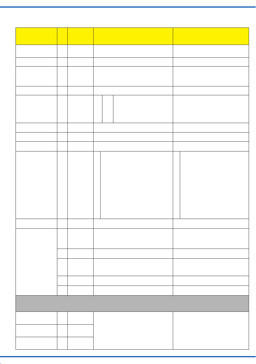
8. CV-Tabelle
8. CV table
Name der CV
CV Name
Adresse
Address
Versionsnummer
Version number
Hersteller
Manufacturer
Adresse MSB
Address MSB
Konguration
Conguration
Position des Antriebs
Position of drive
Richtung
Direction
Stellzeit
Regulating time
Schaltausgang
Function output
Protokoll
Protocol
Dioramamodus / Zufallsteuerung
Diorama mode / Random control
Folgende CVs sind spezielle Einstellungen für die Motorsteuerung. Die Werte sind werksseitig optimiert und sollen in der Regel nicht verändert
werden!
The following CVs are intended for conguring the motor control. The values have been optimized by the producer and should normally not be
changed!
Lastregelparameter KP
Load control parameter
KP
Lastregelparameter KI
Load control parameter
KI
Lastregelparameter KD
Load control parameter
KD
CV-
Eingabe-
Nr.
werte
No.
(Default)
value range
1 0 … 255 (1) Enthält die unteren 8 Bit der Decoderadresse.
7 Nur lesbar! Read only!
8 (109) Nur lesbar! / Reset auf Werkseinstellungen.
9 0 … 7 (0) Obere 3 Bits. Zusammen mit CV 1 wird so die
29 (136) Bit
33 Wird von einigen Zentralen zur Auslesung der
36 (0) 0 = normal, 1 = invertiert 0 = normal, 1 = inverted
37 0 ... 50 (25) Laufzeit des Antriebs in 0,1 Sekunden Schritten. Running time of the drive in 0.1 second steps.
38 (12) 0
40 (1) 0 = DCC; 1 = Motorola 0 = DCC; 1 = Motorola
44 0 ... 255 (120) Diorama-Modus Zeitbegrenzung: maximale
45 0 ... 255 (20) Diorama-Modus, minimale Zeitlänge in Sekunden
46 0 ... 255 (40) Diorama-Modus, maximale Zeitlänge während
47 0 ... 255 (5) Diorama-Modus, minimale Zeitlänge während
48 0 ... 255 (10) Diorama-Modus, maximale Zeitlänge während
51 0 … 255 (75) Reglerparameter Parameters for the motor load control.
52 0 … 255 (40)
53 0 … 255 (10)
Erläuterungen/Hinweise
Zusammen mit CV 9 wird so die Adresse
gespeichert.
Durch Eintragen des Wertes 8 wird der Türantrieb
auf den Auslieferungszustand zurückgesetzt.
Schreiben von Wert 9 setzt alle Werte, außer die
Adresse, auf den Auslieferungszustand zurück.
Adresse gespeichert.
Wert
3
0
7
Position des Antriebs benutzt.
1
2
3
4
5
6
12
Zeitdauer in 15 Sekunden-Schritten. Wert 0
entspricht unendlicher Zeitdauer. Vorsicht, unendlicher Betrieb nur auf eigene Gefahr verwenden,
weil es zu verstärktem Verschleiß führen kann.
während derer die Tür zu ist
derer die Tür zu ist. Wenn CV 45 und 46 unterschiedliche Werte haben, wird ein zufälliger Wert
zwischen den beiden CVs gewählt.
derer die Tür oen ist.
derer die Tür oen ist.
Kein RailCom
8
RailCom eingeschaltet
0
Decoder schaltet auf Lokfunktionen
128
Decoder schaltet auf Schaltartikelbefehle
Inaktiv
Wenn eine Bewegung beendet wird, wird der
entsprechende Ausgang kurz eingeschaltet.
Wenn eine Bewegung startet, wird der ent
sprechende Ausgang kurz eingeschaltet.
Ausgang zeigt den aktuellen Zustand
an. Während der Bewegung sind beide
Ausgänge aus.
Ausgang zeigt den aktuellen Zustand an.
Während der Bewegung ist der alte Zustand
angezeigt.
Ausgang zeigt den aktuellen Zustand an.
Während der Bewegungen ist der neue
Zustand angezeigt.
Decoderadresse+1 schaltet die Ausgänge
als Dauerausgänge um.
Hausbeleuchtung (Grundeinstellung).
Remarks
Contains the lower 8 bits of the decoder
address. Thus the address is saved in conjunction with CV 9.
Read only! / Factory Reset. By entering the
value 8 the door motor is reset to factory
default values. Writing the value 9 resets all
values to default values except for the address.
Upper 3 bits. The address is saved in conjunction with CV 1.
No RailCom
RailCom turned on
Decoder responds to locomotive functions
Decoder responds to switching commands
Used by some command stations for reading
the position of the drive.
0
Inactive
1
Once a movement is nished the corresponding output is switched on for a
moment.
2
Once a movement starts, the corresponding output is switched on for a moment.
3
The output displays the current status.
During movement both outputs are
switched o.
4
The output displays the current status.
During movement the previous status is
still displayed.
5
The output displays the current status.
During movement the new status is
displayed.
6
Decoder address+1 switches the outputs
into permanent mode.
12
House lighting (default setting).
Diorama mode time limit: max. time duration
in 15 second intervals. Value 0 corresponds
to unlimited duration. Attention: use unlimited
operation only at your own risk as it can lead to
increased wear and tear.
Diorama mode, minimal time duration in
seconds during which the door is closed
Diorama mode, maximal time duration during
which the door is closed.
Diorama mode, minimal time duration during
which the door is open.
Diorama mode, maximal time duration during
which the door is open.
18
Page 19

Viessmann
hnik GmbH
www.viessmann-modell.de
Name der CV
CV Name
EMK Messungen
EMF measurements
Reglerperiode
Control period
Empndlichkeit der
Blockierungsdetektierung
Sensitivity of blocking
detection
Maximale Motorleistung
Maximal motor power
Kalibration
Calibration
Weitere CVs nden Sie in Kapitel 4.12, Lichtsteuerung.
More CVs can be found in chapter 4.12, Lighting control.
CV-
Eingabe-
Nr.
werte
No.
(Default)
value range
54 (8) Anzahl von EMK Messungen je Zyklus. Die er-
55 (8) Gesamte Reglerperiode in 0,5 ms. Entire control period in 0.5 msec.
56 (100) Zeit in 10 ms wie lange der Motor nach einer
57 (150) Anzahl der Reglerzyklen nach dem Motorstart,
58 0...255 (255) Wird auf diesen Wert reduziert, sobald 1/8 des
59 0...255 (220) Wird auf diesen Wert reduziert, sobald 6/8 des
60 0...255 (180) Wird auf diesen Wert reduziert, sobald 7/8 des
61 0...255 (100) Wird auf diesen Wert reduziert, sobald 8/8 des
62 (0) Mit Schreiben des Wertes 206 wird eine
Erläuterungen/Hinweise
sten 2 Messungen werden automatisch ignoriert.
erkannten Blockierung weiter angetrieben wird.
Es ist nur dann aktiv, wenn weniger als 3/4 des
Gesamtwegs gefahren sind. In dem letzten
Viertel wird der Motor bei einer Blockierung sofort
abgeschaltet.
ab wann die Blockierungsdetektierung aktiviert
wird.
Weges absolviert wurden.
Weges absolviert wurden.
Weges absolviert wurden.
Weges absolviert wurden.
Kalibrierung der Motorendstufe ausgeführt.
Damit lernt der Decoder wo die Endpunkte der
Bewegung sind.
Remarks
Number of EMF measurements per cycle. The
rst two measurements will be automatically
ignored.
Time in 10 ms that the motor keeps running
after having detected a mechanical resistance
(blocking). It is only active if less than 3/4 of
the entire movement have been completed.
In the last quarter the motor will be turned o
immediately if blocked.
Number of control cycles after the motor has
started from which point on the motor blocking
detection is active.
Will be reduced to this value as soon as 1/8 of
the movement has been completed.
Will be reduced to this value as soon as 6/8 of
the movement has been completed.
Will be reduced to this value as soon as 7/8 of
the movement has been completed.
Will be reduced to this value as soon as 8/8 of
the movement has been completed.
The motor end stage is calibrated when writing
the value 206. Thus the decoder “learns about”
the end positions of the required movement.
Entsorgen Sie dieses Produkt nicht über den
(unsortierten) Hausmüll, sondern führen Sie
es der Wiederverwertung zu.
Änderungen vorbehalten. Keine Haftung für Druckfehler
und Irrtümer.
Die aktuelle Version der Anleitung finden Sie auf der Viessmann Homepage unter der Artikelnummer.
Modellbauartikel, kein Spielzeug! Nicht geeignet für Kinder
DE
unter 14 Jahren! Anleitung aufbewahren!
Model building item, not a toy! Not suitable for children
EN
under the age of 14 years! Keep these instructions!
Ce n’est pas un jouet. Ne convient pas aux enfants de
FR
moins de 14 ans ! C’est un produit décor! Conservez cette
notice d’instructions!
Não é um brinquedo!Não aconselhável para menores de
PT
14 anos. Conservar o manual de instruções.
Modelltec
Bahnhofstraße 2a
D - 35116 Hatzfeld-Reddighausen
info@viessmann-modell.com
Do not dispose of this product through (unsorted)
domestic waste, supply it to recycling instead.
Subject to change without prior notice. No liability for
mistakes and printing errors.
You will find the latest version of the manual on the Viessmann website using the item number.
Modelbouwartikel, geen speelgoed! Niet geschikt voor
NL
kinderen onder 14 jaar! Gebruiksaanwijzing bewaren!
Articolo di modellismo, non è un giocattolo! Non adatto
IT
a bambini al di sotto dei 14 anni! Conservare istruzioni per
l’uso!
Artículo para modelismo ¡No es un juguete! No
ES
recomendado para menores de 14 años! Conserva las
instrucciones de servicio!
85053
Stand 02/sw
Made in Europe
02/2020
Ho/Kf
Page 20

Notizen
Notes
20
 Loading...