

Page 1
- The actuator rod is made from spring steel wire and
can therefore be shortened only with the correct
4551
side cutters. For safe cutting you should hold the
piece you are cutting o with small pliers.
- The motor can be universally used for signals from
dierent manufacturers or for your own hand-built
signals. The connection of the motor to the signal
can be arranged to best suit the requirements dictated by the layout you have planned and built.
3. Function control
Before nal installation you must check the functioning of the unit:
Connect the yellow cable of the drive to one terminal
on the accessories output from your model train controller (14 – 16 V AC~ / DC=).Then if you connect the
brown cable to the other terminal on your controller
and touch the red-banded, blue cable to this terminal,
the actuator wire will extend. Touching the green-banded cable to this terminal will retract the actuator wire.
Note that power must not be supplied both blue cable
simultaneously.
The yellow cable is the common feed to both of the
drive unit solenoids. The red cable allows you to con-
trol other functions such as warning lights, track feeds
etc,.
4. Connection
Reed contact 1 x IN (e. g. for train control): Contact is
closed when the actuator rod is retracted.
Connections for operating the solenoid coils: A pulse
on the red-banded blue cable will extend the actuator rod, a pulse on the green-banded blue cable will
retract it.
Connections for operating the solenoid coils: A pulse
on the red-banded blue cable will extend the actuator rod, a pulse on the green-banded blue cable will
retract it.
Stellantrieb für Signale
Motion drive for signals
Modellbauartikel, kein Spielzeug! Nicht geeignet für Kinder
DE
unter 14 Jahren! Anleitung aufbewahren!
Model building item, not a toy! Not suitable for children
EN
under the age of 14 years! Keep these instructions!
Ce n’est pas un jouet. Ne convient pas aux enfants de
FR
moins de 14 ans ! C’est un produit décor! Conservez cette
notice d’instructions!
Não é um brinquedo! Não aconselhável para menores de
PT
14 anos. Conservar a embalagem.
Modelbouwartikel, geen speelgoed! Niet geschikt voor kin-
NL
deren onder 14 jaar! Gebruiksaanwijzing bewaren!
Articolo di modellismo, non è un giocattolo! Non adatto a
IT
bambini al di sotto dei 14 anni! Conservare instruzioni per
l’uso!
Artículo para modelismo. No es un juguete! No recomen-
ES
dado para menores de 14 años! Conserva las instrucciones
de servicio!
Bedienungsanleitung
Operation Manual
DE
1. Wichtige Hinweise
Bitte lesen Sie vor der ersten Anwendung des Produktes bzw. dessen Einbau diese Bedienungsanleitung aufmerksam durch und bewahren Sie diese auf.
Sie ist Teil des Produktes.
1.1 Sicherheitshinweise
Vorsicht:
Verletzungsgefahr!
Aufgrund der detaillierten Abbildung des Originals
bzw. der vorgesehenen Verwendung kann das Produkt Spitzen, Kanten und abbruchgefährdete Teile
aufweisen. Für die Montage sind Werkzeuge nötig.
Stromschlaggefahr!
5. Trouble-shooting
Problem:
The power supply is doubtlessly working well but the
motor does not switch.
Remedy:
Possible cause: The internal end stop contact is in
an intermediate position. Make sure to switch o the
power supply before moving the reeds gently upwards
with a needle or a ne wire.
6. Technical data
Operating voltage: 14 – 16 V AC~ / DC=
Operating current: 600 mA for 25 msec
Actuator travel: ca 5 mm
Actuator power: ca. 0,1 N
Die Anschlussdrähte niemals in eine Steckdose einführen! Verwendetes Versorgungsgerät (Transformator, Netzteil) regelmäßig auf Schäden überprüfen. Bei Schäden am Versorgungsgerät dieses keinesfalls benutzen!
Alle Anschluss- und Montagearbeiten nur bei abgeschalteter Betriebsspannung durchführen!
Ausschließlich nach VDE/EN-gefertigte Modellbahntransformatoren verwenden!
Stromquellen unbedingt so absichern, dass es bei
einem Kurzschluss nicht zum Kabelbrand kommen
kann.
1.2 Das Produkt richtig verwenden
Dieses Produkt ist bestimmt:
- Zum Einbau in Modelleisenbahnanlagen und
Dioramen
- Zum Anschluss an einen Modellbahntransformator
(z. B. Art. 5200) bzw. an einer Modellbahnsteuerung mit zugelassener Betriebsspannung.
- Zum Betrieb in trockenen Räumen.
Jeder darüber hinausgehende Gebrauch gilt als nicht
bestimmungsgemäß. Für daraus resultierende Schäden haftet der Hersteller nicht.
1.3 Packungsinhalt überprüfen
Kontrollieren Sie den Lieferumfang auf Vollständigkeit:
- Signalmotor mit Anschlusskabeln
- Haltering
- Anleitung
Do not dispose of this product through
(unsorted) domestic waste, supply it to
recycling instead.
Subject to change without prior notice. No liability for
mistakes and printing errors.
You will nd the latest version of the manual on the
Viessmann website using the item-No.
Viessmann
Modelltechnik GmbH
Bahnhofstraße 2a
D - 35116 Hatzfeld-Reddighausen
www.viessmann-modell.de
Stand 03/sw
Made in Europe
4 1
2. Einbau
- Signalmotor vorsichtig aus der Verpackung nehmen.
- Vor dem Einbau auf Funktion prüfen.
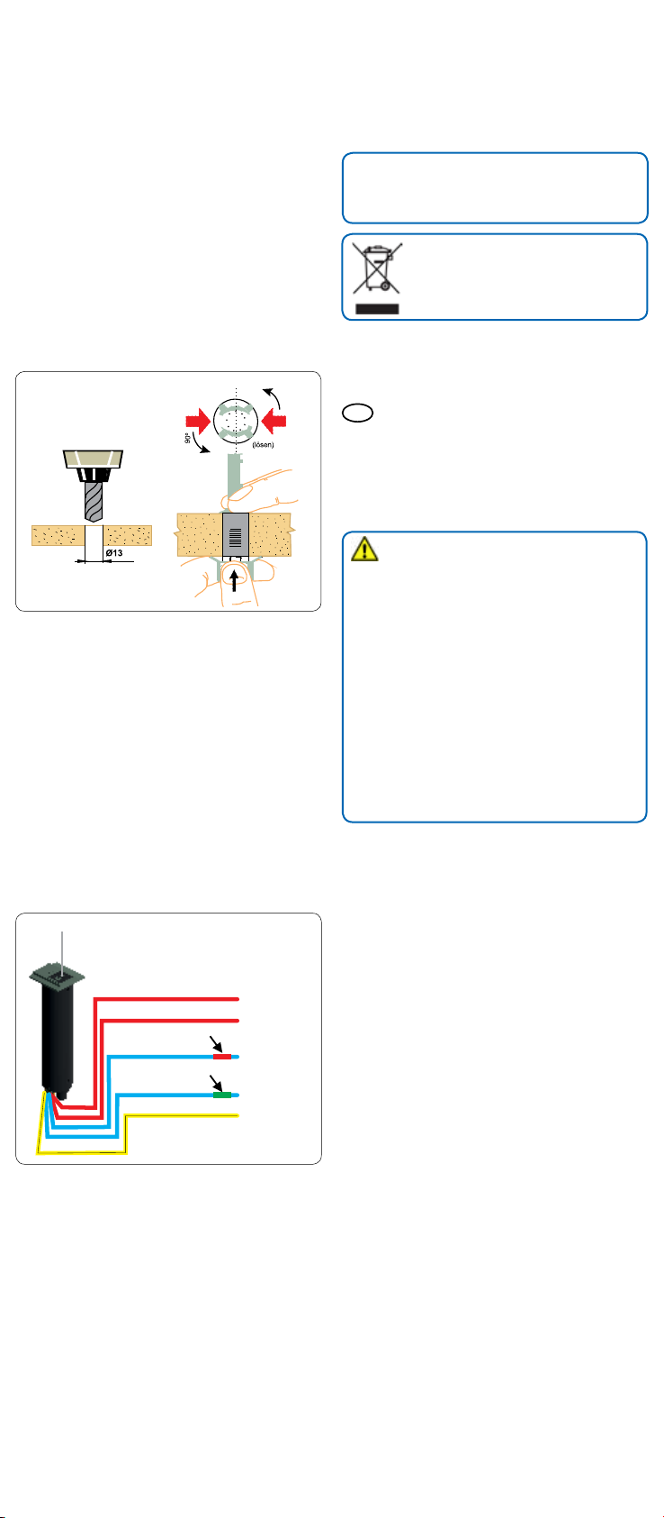
- Am Einbauort ein Loch (Ø 13 mm) zur Montage
bohren (Abb. 1).
- Motor mit den Anschlusskabeln von oben in die Bohrung stecken. Von unten den Haltering aufschieben.
98143
09/2018
Ho/Kf
Darauf achten, dass die Rastnasen um 90° zu der
Rielung am Gehäuseblech des Antriebs verdreht
sind. Stehen nun die vier Kunststoenden des Be-
festigungsringes mit der Grundplatte unter mechanischer Spannung, wird der Ring so gedreht, dass
Page 2
die Nasen in der Rielung des Bleches für festen
Halt sorgen. Hierbei muß der Sockel des Signalmotors von oben festgehalten werden.
- Stellen Sie die mechanische Verbindung zu dem zu
bewegenden Modell her. Die Montage des Antriebs
kann senkrecht oder waagerecht erfolgen. Über Umlenkhebel o. ä. können nahezu alle Bewegungsarten
erzeugt werden.
Beachten Sie jedoch folgende Hinweise:
- Der Stelldraht ist ein Federstahldraht und darf daher
nur mit dafür geeigneten Seitenschneidern gekürzt
werden (aus Sicherheitsgründen sollte auch der abzuschneidende Teil des Drahtes festgehalten werden, vorzugsweise mit einer kleinen Flachzange).
- Der Motor ist universell für Signale verschiedenster
Hersteller bzw. für Selbstbau-Signale verwendbar.
Die Verbindung von Motor zum Signal ist jedoch
individuell verschieden und muss vom Anwender
selbst konstruiert und gebaut werden. Hier sind Ihrer
Fantasie lediglich durch die physikalischen Gesetzmäßigkeiten Grenzen gesetzt.
Abb. 1
Fig. 1
3. Funktionskontrolle
Zum Test des Packungsinhalts das gelbe Kabel des
Signalmotors an einem Pol des Magnetartikelausgangs eines Modellbahntransformators (14 – 16 V
AC~/DC=) anschließen. Beim Anschluss der blauen
Kabel an den anderen Pol des Trafos ergeben sich
folgende Funktionen:
blau mit roter Markierung:
Der Stelldraht fährt heraus
blau mit grüner Markierung:
Der Stelldraht fährt hinein
Die blauen Kabel dürfen jedoch nie beide gleichzeitig
angesteuert werden! Das gelbe Kabel ist der gemeinsame Mittelpunkt der Antriebsspulen. Mit den beiden
roten Kabeln können weitere Funktionen gesteuert
werden (z. B. Blinkelektronik für Andreaskreuze, Fahrstrom usw.).
Abb. 2
rot / red
rot / red
rote markierung / red-banded
blau / blue
grüne markierung / green-banded
blau / blue
gelb / yellow
Fig. 2
Abhilfe: Mögliche Ursache: Der innenliegende Endab-
schaltungskontakt bendet sich in einer Zwischenposition. Zunächst Strom abschalten! Dann Schaltkontakte
mit Hilfe einer Stecknadel oder mit Hilfe eines dünnen
Drahtes einmal nach oben bewegen.
6. Technische Daten
Betriebsspannung: 14 – 16 V AC~ / DC=
Stromaufnahme: 600 mA für 25 msec
Hub: ca. 5 mm
Stellkraft: ca. 0,1 N
Entsorgen Sie dieses Produkt nicht
über den (unsortierten) Hausmüll, sondern führen Sie es der Wiederverwertung zu.
Änderungen vorbehalten. Keine Haftung für Druckfehler
und Irrtümer.
Die aktuelle Version der Anleitung nden Sie auf der
Viessmann Homepage unter der Artikelnummer.
EN
1. Important information
Please read this manual completely and attentively
before using the product for the rst time. Keep this
manual. It is part of the product.
1.1 Safety instructions
Caution:
Risk of injury!
Due to the detailed reproduction of the original and
the intended use, this product can have peaks,
edges and breakable parts. Tools are required for
installation.
Electrical hazard!
Never insert the connecting wires into a power
socket! Regularly examine the transformer for damage. In case of any damage, do not use the transformer.
Make sure that the power supply is switched o
when you mount the device and connect the
cables!
The power sources must be protected to avoid the
risk of burning cables.
1.2 Using the product for its correct
purpose
This product is intended:
- For installation in model train layouts and dioramas.
- For connection to an authorized model train transformer (e. g. item 5200) or a digital command station.
- For operation in dry rooms only.
Using the product for any other purpose is not approved and is considered inappropriate. The manufacturer is not responsible for any damage resulting from
the improper use of this product.
1.3 Checking the package contents
Check the contents of the package for completeness:
- Motion drive
- Fixation ring
- Manual
2. Mounting
4. Anschluss
Schaltkontakt 1 x EIN (z. B. für Zugbeeinussung):
Kontakt ist geschlossen, wenn der Stelldraht kurz bzw.
eingefahren ist.
Anschlüsse zum Stellen des Motors. Ein Spannungsimpuls auf der blauen Leitung mit der roten Markierung lässt den Stelldraht aus dem Motor herauskommen (entsprechend grün = hinein).
Das gelbe Anschlusskabel ist der gemeinsame Anschluss beider Motorspulen und wird an einem Pol des
Lichtstromausganges Ihres Modellbahntransformators
angeschlossen.
5. Fehlersuche und Abhilfe
Fehler: Die Stromzuführung ist zweifelsfrei in Ordnung, der Motor schaltet aber nicht.
2 3
- Remove the motion drive carefully from the
package.
- Check function before mounting.
- Drill a hole (Ø 13 mm) at the mounting place (g. 1).
- Insert the cables from outside into the hole and
push the drive into the hole. Fix the drive with the
xation ring from inside. Lock into position by rotating the ring 90 degrees to engage its lugs with the
grooves in the metal motor casing. During this operation the top of the signal motor must be held fast
from above.
- Establish the mechanical connection to the moving
part of your model. The drive unit can be mounted
vertically or horizontally and you can arrange the
pivoting linkage in the way most appropriate for
your own particular application. Please note the
following instructions:
 Loading...