

Page 1
Gebrauchsanleitung
Manual
Manual
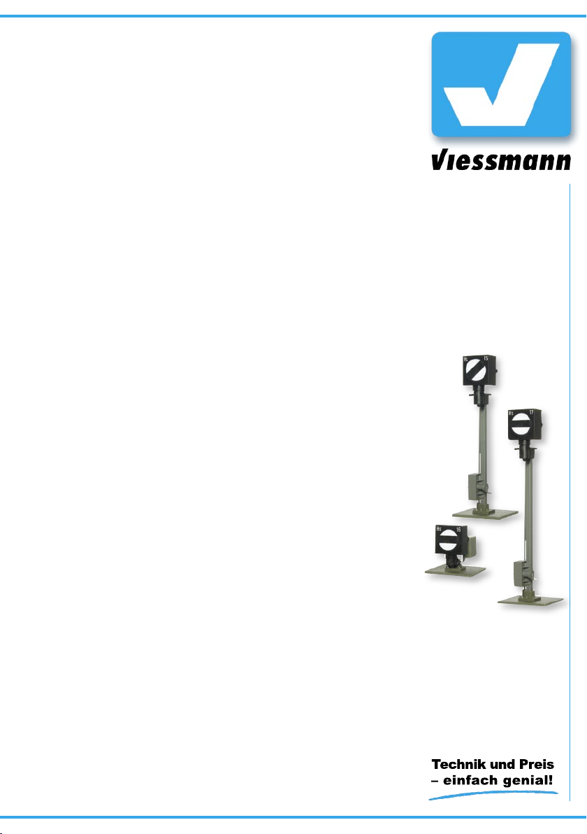
Form-Sperrsignale
zweibegriffig, mit einem Antrieb
Semaphore Stop Signals
two-aspect signals, with one drive unit
H0: 4515, 4516, 4517
TT: 4909
N: 4409
Z: 4809
1. Wichtige Hinweise ...................................... 2
2. Einleitung ................................................... 2
3. Bezeichnung von Sperrsignalen ................ 3
4. Funktionskontrolle ...................................... 3
5. Montage ..................................................... 4
6. Anschluss ................................................... 5
7. Fehlersuche & Abhilfe ................................ 8
8. Technische Daten ...................................... 8
1. Important Information ................................. 2
2. Introduction ................................................ 2
3. Marking of Stop Signals ............................... 3
4. Checking the Function ................................. 3
5. Mounting ..................................................... 4
6. Connections ............................................... 5
7. Troubleshooting .......................................... 8
8. Technical Data ............................................ 8
Page 2
2
D
GB
1. Wichtige Hinweise
Lesen Sie vor der ersten Benutzung des Produktes bzw. dessen Einbau diese Anleitung komplett
und aufmerksam durch. Bewahren Sie diese Anleitung auf. Sie ist Teil des Produktes.
Das Produkt richtig verwenden
Dieses Signalmodell ist bestimmt
– zum Einbau in Modelleisenbahnanlagen
– zum Anschluss an einen zugelassenen Modell-
bahntransformator bzw. an eine damit versorg-
te elektrische Steuerung
– zum Betrieb in trockenen Räumen.
Jeder darüber hinausgehende Gebrauch gilt als
nicht bestimmungsgemäß. Für daraus resultierende Schäden haftet der Hersteller nicht.
2. Einleitung
Sperrsignale gehören der Kategorie der Rangiersignale an und haben einen vielfältigen Aufgabenbereich. Sie stehen in der Regel – in Fahrtrichtung
gesehen – rechts vom Gleis.
Grundsätzlich unterscheidet man beim Vorbild
zwischen Zug- und Rangierfahrten. Während Zugfahrten die Fahrten von Bahnhof A über die freie
Strecke nach Bahnhof B bezeichnen, finden Rangierfahrten grundsätzlich innerhalb von Bahnhöfen bzw. Bahnbetriebswerken oder auch Hafenund Industrieanlagen statt.
Hauptsignale (z. B. Viessmann 4400 / 4500 /
4800 / 4900 oder 4401 / 4501 / 4801 / 4901) gelten nur für Zugfahrten, Sperrsignale hingegen für
Rangierfahrten.
Ein großes Einsatzgebiet der Sperrsignale liegt in
Rangierbereichen. Die Signale werden am Anfang
von Rangierwegen aufgestellt. Das ist grundsätzlich nur in Bahnhofsbereichen erforderlich – z. B.
am Ende von Bahnsteiggleisen und der Einmündung von Abstellgleisen.
In Rangierbereichen sollten die Sperrsignale so
dicht wie möglich am Ende des Gleises stehen,
d. h. direkt vor dem Grenzzeichen oder dem Weichenanfang. Zwischen den Gleisen sollte dabei
mindestens ein Abstand von 51 mm (H0), 37 mm
(TT), 28 mm (N) bzw. 20 mm (Z) zur Aufstellung
des Signals vorhanden sein.
Mit dem Viessmann-Modell des Form-Sperrsignals können Sie die Vorbildsituation originalgetreu
wiedergeben.
Der in der Scheibe integrierte Balken des Signals
1. Important Information
Please read this manual prior to first use of the
product resp. its installation! This product must
only be used as required in this manual. Keep this
manual. It is part of the product.
Using the product for it’s correct
purpose
This model of a signal is intended
– for installation in model railroad layouts.
– for connection to an authorized model railroad
transformer or an electrical control system connected to one
– for operation in a dry area
Using the product for any other purpose is not
approved and is considered incorrect. The manufacturer cannot be held responsible for any damage resulting from the improper use of this product.
2. Introduction
Stop signals belong to the group of shunting signals and are used in many ways. Normally these
signals are located on the right hand side of the
track when viewed in the direction of travel.
The prototype differentiates between train- and
shunting movements. While train movements are
taking place from station A to station B via the
main line, shunting is generally only permitted
within the station limits, in locomotive depots or
perhaps in industrial sidings or yards in a harbour.
Home and exit signals (e.g. Viessmann 4400 /
4500 / 4800 / 4900 or 4401 / 4501 / 4801 / 4901)
are only used for train movements, stop signals
for shunting and for train movements in conjunction with the exit signal.
Stop signals are generally used within a station,
namely on those tracks, which are mainly used
for shunting. You find them at the start of a typical shunting route. They are only necessary within the station limits e.g. at the end of the platform
tracks and where auxiliary tracks merge with the
main tracks.
Stop signals should be as close to the end of the
track as possible, that is directly in front of the
shunting limit signal or at the beginning of the
point. The distance between the tracks should be
at least 37 mm (TT), 28 mm (N) resp. 20 mm (Z)
to allow sufficient space for the signal.
With the Viessmann model of the semaphore stop
Page 3
3
Hs
15
Fig. 1
Abb. 1
wird durch den Kompaktantrieb vorbildgerecht
langsam bewegt.
Der Antrieb ist mit einem Zugbeeinflussungskon
takt ausgestattet. So fährt die Lok erst dann los,
wenn auf Sh1 (Rangierverbot aufgehoben) ge
-
schaltet wird.
Finden auf einem Gleis Zug- und Rangierfahr
ten statt (z. B. auf Bahnsteiggleisen), so wird das
Sperrsignal in der Regel direkt vor dem Hauptsi
-
gnal platziert. Hier gilt bei Formsignalen folgen
-
de Regel: Auch für Zugfahrten muss das Sperrsi
gnal auf Sh1 (d. h. „Rangierverbot aufgehoben“)
gestellt werden. Dieses bedeutet, dass im Modell
bei der Kombination „Form-Sperrsignal vor FormHauptsignal“
nur der Zugbeeinflussungskontakt
des Sperrsignals am Halteabschnitt angeschlos
sen werden darf. Der Zugbeeinflussungskontakt
des Hauptsignals wird dann nicht verwendet.
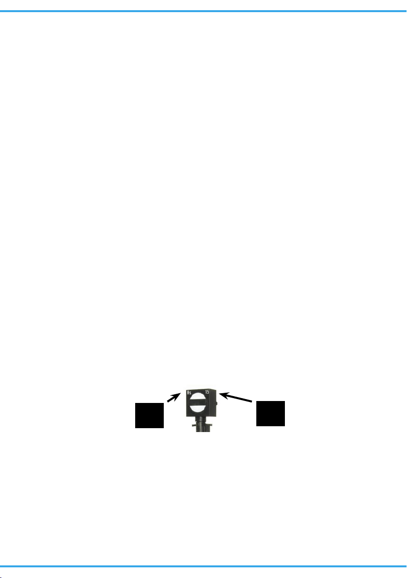
3. Bezeichnung von
Sperrsignalen
Dem Signal ist eine Tafel mit selbstklebenden Be
zeichnungsschildern beigelegt. Schneiden Sie die
gewünschten Bezeichnungsschilder aus und kle
ben Sie es nach Abziehen der Schutzfolie auf den
Signalkasten auf.
Hier einige Richtlinien zur korrekten Beschriftung
von Sperrsignalen:
Sperrsignale werden mit der Gleisnummer des
Gleises bezeichnet, an dessen Ausfahrt sie ste
hen. Werden mehrere Sperrsignale an einem
Gleis aufgestellt, so tragen diese zur Unterschei
dung noch zusätzlich eine hochgestellte römische
Ziffer (z. B. 4
I
, 4
II
, 4
III
…).
Außerdem wird bei Hauptsperrsignalen ein „Hs“Schild links oben am Signalkasten angebracht.
signal you can replicate the prototype down to the
last detail.
The signal bar, mounted in front of the disk, can
be moved at a prototypical slow speed by the
compact drive.
The drive is equipped with an electrical contact for
train control. Thus the locomotive only starts mov
-
ing once the signal is set to Sh1 (shunting prohibi
-
tion canceled).
If a track is used for train and shunting move
-
ments (e.g. on station tracks), the stop signal is lo
-
cated directly in front of the exit signal. For sema
phores the following rule applies: the stop signal
has to be set to Sh1 for both train and shunt
-
ing movements (that is “shunting prohibition can
-
celed”). On the model train layout
only
the con
tacts of the stop signal are used for train control
when the semaphore stop signal is located in front
of the semaphore exit signal. The contacts of the
exit signal are not be used in this case.
3. Marking of Stop Signals
Adhesive signs are supplied with the signal. Sim
-
ply cut out the desired sign and attach it to the sig
nal box after removing the protecting foil. Here are
some rules for the correct marking of the stop sig
-
nals:
Stop signals are marked with the number of that
track, where they are located. If several stop sig
nals are located at the same track, they have an
additional roman number, which is slightly raised
(e.g. 4
I
, 4
II
, 4
III
…).
On combined exit-stop signals a sign “Hs” is
placed on the left upper corner of the signal box.
4. Funktionskontrolle
Nehmen Sie das Signal vorsichtig aus der Verpa
-
ckung. Führen Sie vor der Montage eine Funkti
-
onskontrolle durch.
Schließen Sie dazu das gelbe Kabel an einem Pol
eines 16 V-Modellbahntransformators (AC/DC) –
z. B.
Viessmann
5200 – an.
Verbinden Sie abwechselnd jeweils ein blaues Ka
bel mit dem anderen Pol des Trafos. Schließen
Sie niemals beide blauen Kabel gleichzeitig an.
Das kann zur Zerstörung des Signals führen.
4. Checking the Function
Remove the signal from the box carefully. Check
all functions prior to installation.
Connect the yellow wire to one of the terminals
of a 16 V transformer (AC/DC) e. g.
Viessmann
5200. Then alternately make contact between the
blue cables and the other terminal, but only briefly.
This results in switching the signal as follows:
Page 4

4
Fig. 3Abb. 3 Fig. 4
90°
15 mm
15 mm
Ø 6 mm
Abb. 4
Fig. 2
Abb. 2
Sh0 (Rangierverbot)
Sh0 (shunting prohibited)
Sh1 (Rangierverbot aufgehoben)
Sh1 (shunting allowed)
blaues Kabel mit roter Markierung
blue cable with red marking
blaues Kabel mit grüner Markierung
blue cable with green marking
5. Montage
1) Prüfen Sie vor dem Einbau des Signals, wie im
Punkt „Funktionskontrolle“ beschrieben, des
-
sen einwandfreie Funktion.
2) Beschriften Sie das Signal gemäß den Hinwei
-
sen auf Seite 3.
3) Sägen Sie an der Montagestelle ein Loch mit
den Maßen 15 mm x 15 mm. Bohren Sie dazu
zuerst 4 Löcher mit 6 mm Durchmesser. Ver
wenden Sie die in der Abbildung 3 abgedruckte
Schablone.
4) Führen Sie die Anschlusskabel von oben durch
das Montageloch und stecken Sie dann das Si
-
gnal mit dem Antrieb voran hinein.
5) Halten Sie die Bodenplatte des Signals jetzt
von oben fest. Schieben Sie den Befestigungs
ring von unten so auf den Antrieb, dass die
Rastnasen um 90° zu der Riffelung am Gehäu
se des Antriebes verdreht sind. Wenn nun die 4
Kunststofflaschen des Befestigungsringes mit
der Anlagenplatte unter mechanischer Span
nung stehen, drehen Sie den Ring so, dass die
Nasen in der Riffelung des Antriebsgehäuses
für einen festen Halt sorgen.
5. Mounting
1) Check that the signal works properly as per the
instructions above before you start installing it
on the layout.
2) Letter the signal in accordance with the instruc
-
tions on page 3.
3) Saw a square hole of 15 mm x 15 mm at the
mounting place. But before 4 holes of 6 mm di
ameter each should be drilled in the corners.
Please use the pattern which is shown in figure
3.
4) The signal‘s connection wires have to be insert
ed into the hole first. After that put the signal
with the drive first into that hole.
5) Now the base plate of the signal has to be held
in place (perhaps by a second person). Then
push the mounting ring from below onto the
drive in such a manner that the tabs are at a
right angle to the groves on the housing of the
drive. Once the 4 plastic tabs of the mounting
ring are under tension, you turn the ring until
the tabs lock against the groves on the hous
-
ing.
Page 5

5
Fig. 5
Abb. 5
blau mit roter Markierung
blue with red marking
blau mit grüner Markierung
blue with green marking
gelb + Widerstand / Markierung
yellow wi th resistor or marker
gelb
yellow
braun (+Diode bei LED-Licht)
brown (+diode for LED lighting)
rot
red
rot
red
Signal Sh0 (Rangierverbot)
Signal Sh0 (shunting prohibited)
Signal Sh1 (Rangierverbot aufgehoben)
Signal Sh1 (shunting allowed)
gemeinsamer Mittelpunkt der Antriebsspulen
common pole for the drive coils
Licht
Light
Licht (Masse)
Light (ground)
Kontakt für Zugbeeinflussung
contact for train control
Kontakt für Zugbeeinflussung
contact for train control
6. Anschluss
Alle Anschluss- und Montagearbeiten dürfen
nur bei abgeschalteter Betriebsspannung
durchgeführt werden!
Verwenden Sie nur nach VDE /EN-gefertigte
Modellbahntransformatoren!
Sichern Sie die Stromquellen unbedingt so
ab, dass es bei einem Kurzschluss nicht
zum Kabelbrand kommen kann.
Die Betriebsspannung beträgt 16 V = / ~.
Achtung Art.-Nr. 4809!
Die in der Baugröße Z übliche Spannung
von 10 V reicht nicht zum Betrieb der
Viessmann-Formsignale aus. Verwenden
Sie deshalb einen separaten Transformator
für 16 V (z. B. den Viessmann-Trafo 5200).
Schließen Sie nun das Signal gemäß den Abbildungen 6 oder 7 an. Zur Bedeutung der Kabelfarben siehe Abbildung 5.
Für die Versorgung der Signalbeleuchtung empfehlen wir einen separaten Transformator. Das
verhindert ein Flackern der Beleuchtung beim Umschalten des Signales durch den erhöhten Strombedarf des Antriebes.
Schließen Sie die Signalbeleuchtung über das
gelbe Kabel (mit Widerstand) und das braune Kabel an. Die Signale haben eine LED-Beleuchtung,
daher befindet sich am Ende des braunen Kabels
eine Schutzdiode. Entfernen Sie nie Widerstand
oder Schutzdiode. Eine Umhüllung des Widerstandes mit Isolationsmaterial verhindert eine ausreichende Kühlung.
Gleichstrombetrieb: Schließen Sie die beiden
gelben Kabel an den Minuspol des Trafos an.
6. Connections
Make sure that the power supply is switched
off when you mount the device and connect
the wires!
Only use VDE/EN tested special model train
transformers for the power supply!
The power sources must be protected to prevent the risk of burning wires.
The operating voltage is 16 V (AC/DC).
Warning art. no. 4809!
Contrary to the commonly used 10 V supply for Z gauge layouts Viessmann signals
require a 16 V supply. Please use a separate and dedicated 16 V transformer for the
power supply of these signals!
Now make the electrical connection as per figure
6 or 7.
As a supply for the signal light, we recommend a
separate transformer. This will prevent flickering of
the lights due to high consumption of the drive.
Connect the signal light to the transformer via the
yellow cable (with resistor) and the brown cable.
The signals have LED lighting. Therefore they
have a diode at the end of the brown cable.
The resistor and the diode at the end of the wires
for the lighting must not be removed! Otherwise
the LED in the light box of the signal would become damaged! To avoid overheating do not wrap
the resistor with insulation tape.
Direct current: Connect both yellow cables to the
negative pole of the transfomer.
Page 6

6
Fig. 6Abb. 6
E
rt bn rt 1 gn rt 2 gn
ON
1
2
3
4
5
6
7
8
WP
Viessmann
5211
Magnetartikeldecoder
rt bn E gn 4 rt gn 3 rt
Adresse
16 V = / ~
1,5 kOhm
1/4 Watt
Viessmann
Form-Sperrsignale
Viessmann
semaphore stop signals
Zu weiteren
Decodern
to further
decoders
blau
blue
rot red
braun brown
16 V = / ~
rot red
braun brown
gelb
yellow
braun brown
gelb yellow
rot red
Analoge Ansteuerung
Der konventionelle Anschluss des Sperrsignals ist
in Abbildung 7 auf Seite 7 dargestellt. Die Stromversorgung erfolgt über das braune und die beiden gelben Anschlusskabel. Die mit farbigen Markierungen versehenen blauen Kabel werden über
Kontakte (Einzeltaster, Gleiskontakte, Schaltgleise oder Tastenstellpulte) gegen das braune Anschlusskabel (= „Masse“) geschaltet. Es dürfen jedoch niemals beide blauen Anschlusskabel gleichzeitig angesteuert werden.
Die beiden roten Anschlusskabel des Signals
schalten je nach Signalstellung den Strom im isolierten Halteabschnitt zu oder ab.
Digitale Ansteuerung
Das Formsignal kann auch mit einem Digitalsystem über einen Digital-Decoder (z. B.
Viessmann 5211 für Märklin / Motorola-Format,
5212 für das NMRA-DCC-Format oder 5260 für
SELECTRIX®) angesteuert werden (Abb. 6).
Analogue Wiring
The conventional wiring is shown in figure 7. Power is supplied via the brown wire and the two yellow wires. The blue wires with the coloured markings are connected to contacts (single momentary
switches, track contacts, automatic track switches, control panel), which in turn are wired to the
brown lead ( = “ground”). Never supply power to
both blue wires at the same time.
The red wires are used to connect the insulated
track section to the signal contacts (train control).
Digital Control
The semaphore stop signal can also be ope-rated
with a digital system. Simply connect the wires to
a digital decoder (e.g. Viessmann 5211 for Märklin / Motorola format, 5212 for the NMRA DCC format or 5260 for SELECTRIX®). Also refer to figure 6.
Page 7

7
Universal Tasten - Stellpult
5549
Viessmann
braun
brown
grün
green
rot
red
braun
brown
blau
blue
rot
red
rot
red
braun
brown
gelb
yellow
z. B.
5549
Widerstand
resistor
Diode*
diode*
14 – 16 V ~
Universal Tasten - Stellpult
5549
Viessmann
braun
brown
grün
green
rot
red
braun
brown
blau
blue
rot
red
rot
red
braun
brown
gelb
yellow
z. B.
5549
Widerstand
resistor
System
Märklin H0
Beachten Sie die Anschlusshinweise in Kapitel 6, Seite 5.
Note the connecting instructions in chapter 6 on page 5.
Dieses Symbol neben dem
Gleis kennzeichnet eine
Trennstelle (Gleichstrom =
rechte Schiene in Fahrtrichtung, Wechselstrom = Mittelleiter).
This sign beside the track indicates a track insulation (DC
= right rail in driving direction,
AC = third rail).
Fig. 7
Abb. 7
Fig. 8
Abb. 8
Nadel oder
dünner Draht
Needle or
thin wire
Diese Maßnahme
darf nur im stromlosen Zustand ausgeführt werden!
Switch off power
before doing this!
1. 2. 3.
Page 8

Dieses Produkt ist kein Spielzeug. Nicht geeignet für
Kinder unter 14 Jahren! Anleitung aufbewahren!
This product is not a toy. Not suitable for children
under 14 years! Keep these instructions!
Ce produit n’est pas un jouet. Ne convient pas aux
enfants de moins de 14 ans ! Conservez ce mode
d’emploi !
Dit produkt is geen speelgoed. Niet geschikt voor kinderen onder 14 jaar! Gebruiksaanwijzing bewaren!
Questo prodotto non è un giocattolo. Non adatto a
bambini al di sotto dei 14 anni! Conservare instruzioni per l’uso!
Esto no es un juguete. No recomendado para menores
de 14 años! Conserva las instrucciones de servicio!
8
Modellspielwaren GmbH
08/2006 Bau
Stand 03
Sach-Nr. 98477
Made in Europe
7. Fehlersuche & Abhilfe
1. Die Blende steht nicht gerade.
Signal auf Stellung Sh0 (Rangierhalt) stellen
und Blende vorsichtig gerade stellen (die Blende lässt sich auf Ihrer Drehachse verstellen).
2. Das Signal schaltet hörbar – die Blende bewegt sich jedoch nicht oder nur teilweise.
Hubstange vorsichtig etwas nach oben und un-
ten bewegen (evtl. Hubstange oben lösen und
prüfen, ob die Blendenmechanik sich widerstandslos bewegen lässt).
3. Die Signallampe leuchtet und die Stromzuführung ist zweifelsfrei in Ordnung, das Signal schaltet aber nicht.
Mögliche Ursache: Der innenliegende Rich-
tungsumschalter hat keinen Kontakt.
Strom abschalten! Dann Schaltkontakte mit Hil-
fe einer Stecknadel oder mit Hilfe eines dünnen
Drahtes einmal nach oben bewegen (Abb. 8).
4. Der Lichtkasten leuchtet nicht, obwohl die
Stromzuführung zweifelsfrei in Ordnung ist.
Mögliche Ursache: Vermutlich ist die LED im
Lichtkasten zerstört. Eine LED hat in der Regel
eine praktisch unbegrenzte Lebensdauer. Zerstört wird sie lediglich durch Überstrom (z. B.
Blitzschlag, Betrieb ohne den Schutzwiderstand, etc.).
Die LED können Sie nicht selbst auswechseln.
Schicken Sie das Signal in diesem Fall zur Reparatur direkt an die Fa. Viessmann (Adresse
siehe unten).
7. Troubleshooting
1. The bar is not straight.
Set the signal to the Sh0 aspect (shunting pro-
hibition) adjust the bar back to the straight position very careful! The bar can be shifted on its
axle.
2. The switch sound of the signal drive can be
heard, but the bar doesn‘t move or moves
only a little bit.
Move the lifting rod very carefully a bit up and
down (if necessary detach the lifting rod from
the bar lever and check if bar mechanics can
be moved without resistance).
3. The signal lamp lights and the power supply
doubtless is in good order, however the signal doesn‘t switch.
Possible reason: The inner limit switch hasn‘t
got any contact.
Switch off the electrical power!! Than move up
the switch contact by means of a pin or a thin
wire (refer to figure 8).
4. The light box doesn‘t shine, although the
the power supply doubtless is
in good order.
Possible reason: Probably the LED in the light
box is defective. A LED normally has got an unlimited lifetime. It becomes defective only by
excess current (e.g. stroke of lightning, operating without resistor).
A LED can‘t be replaced by the user. Send the
signal directly for repair to the Viessmann company (see below for address).
09/2007 Ko
Stand 04
Sach-Nr. 98477
Made in Europe
8. Technical Data
Operating voltage: 16 V AC/DC
Peak inrush current (for approx. 0.1 s): 0.7 A
Max. contact load of
the track control contact: 2 A
8. Technische Daten
Betriebsspannung: 16 V =/~
Stromaufnahme
(im Schaltmoment, ca. 0,1 s): 0,7 A
Maximale Belastbarkeit
des Fahrstromkontaktes: 2 A
 Loading...