

Page 1
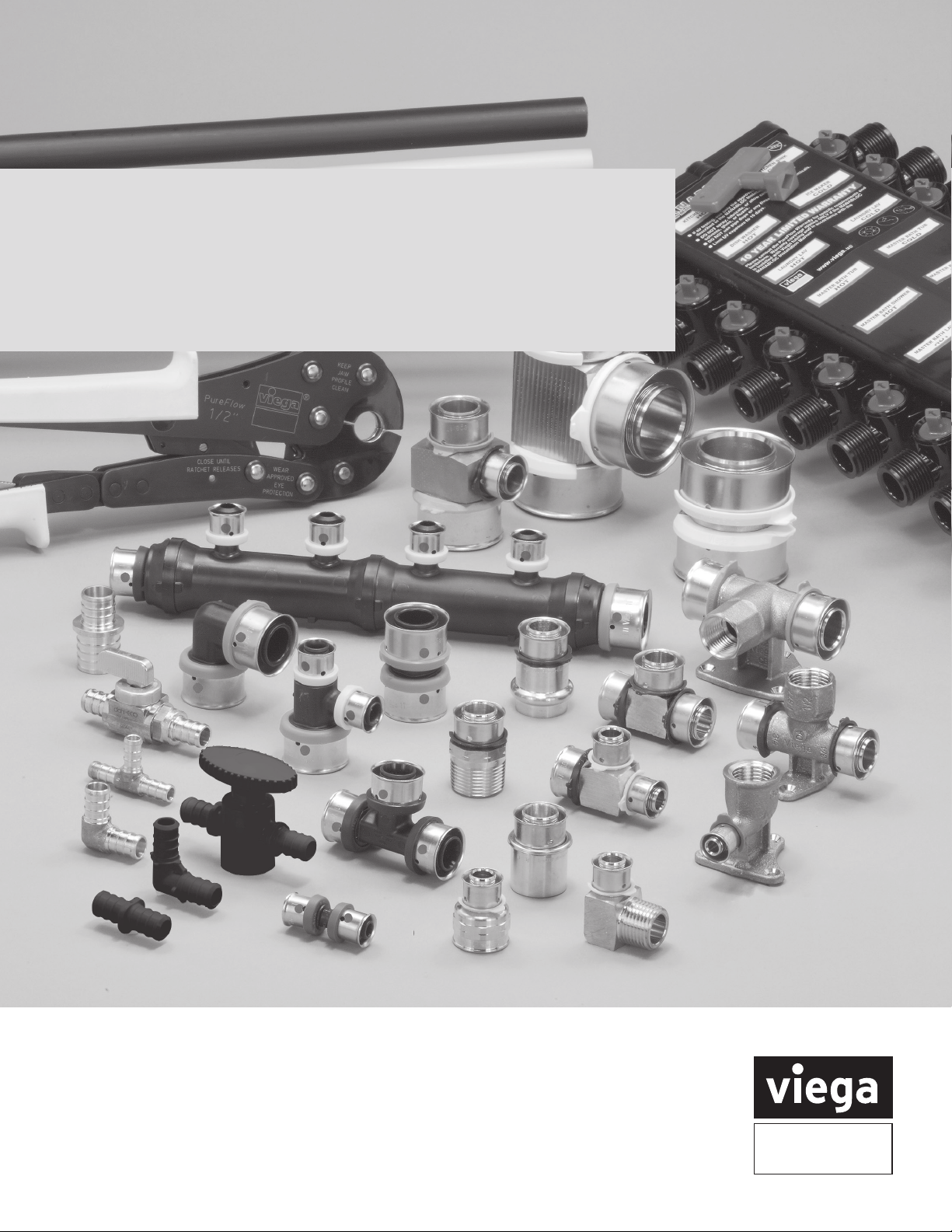
Viega PEX Water Systems
Installation Manual
The global leader
in plumbing, heating
and pipe joining systems
Page 2
Welcome
Viega, heritage of quality, vision for the future
Viega’s heritage of superiority demands nothing but
the best for our customers. Engineered to be efficient,
Viega products perform at the highest possible level
of quality, providing confidence and peace of mind.
Viega is the only manufacturer to offer press systems
in multiple pipe joining materials, including polymer.
More than one million Viega press fittings are installed
every day around the world and, with a Supply Chain
that can process orders in 48 hours or less, Viega
is positioned to provide customers the best, most
versatile support in the industry.
MANUAL CONTENT AND USE
It is the responsibility of the contractor,
specifying engineer or installer to appropriately
design the PEX system, determine that the
selection of components in the system are
the proper ones for the intended application
in the locale in which they will operate and
that employees working on the job site
observe the proper installation practices.
Important notice
This installation guide is intended for traditional (branch
and tee) plumbing systems and combination plumbing
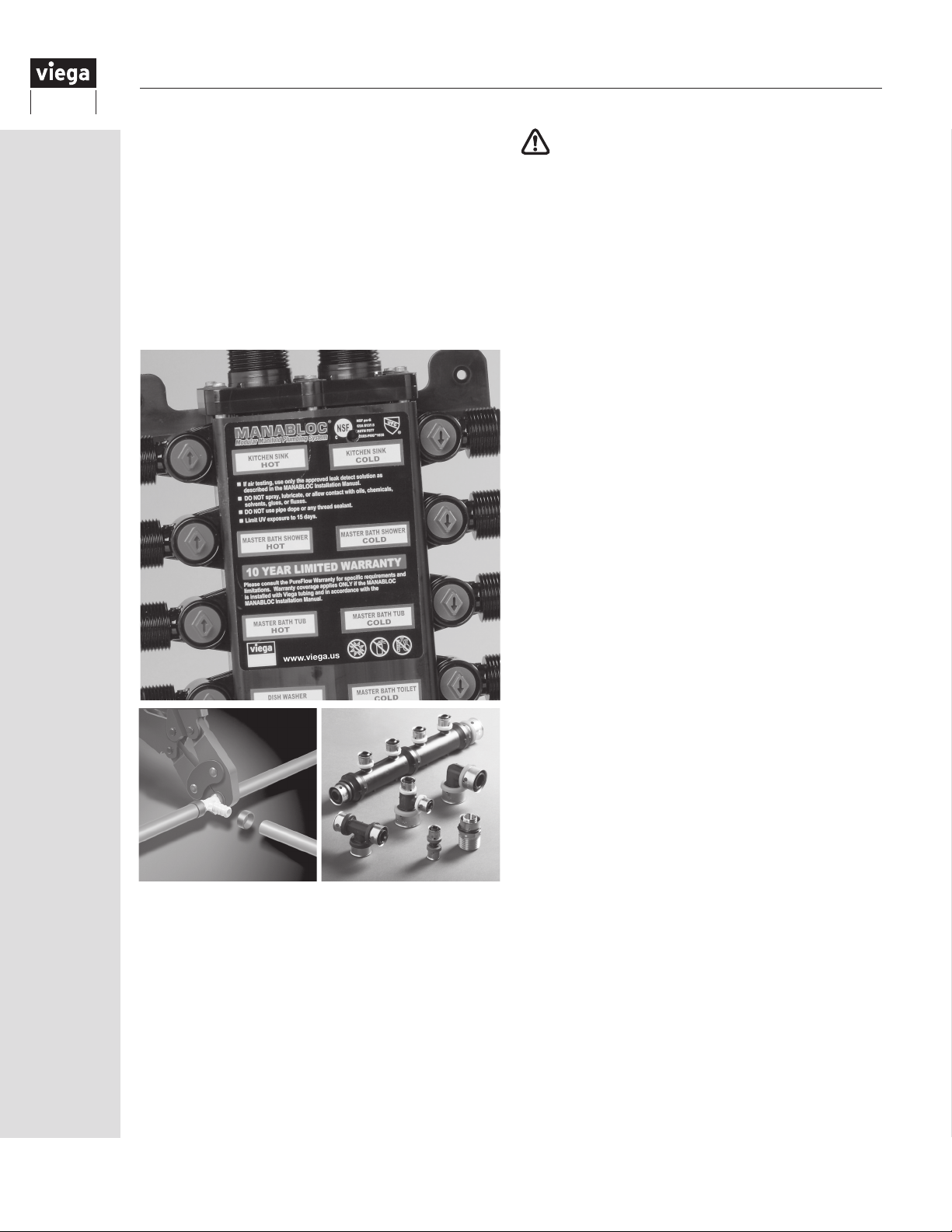
systems using termination manifolds, ManaBloc and
MiniBloc parallel / manifold plumbing system.
NOTE: References to ViegaPEX Ultra tubing made
throughout this publication include the entire line of Viega
cross-linked polyethylene products.
NOTE:
the lead-free requirements of NSF 61-G through testing
under NSF/ANSI 372 (0.25% or less maximum weighted
average lead content).
Zero Lead identies Viega
In the event of conflict or inconsistency between these
installation guidelines and local building or plumbing
codes, local codes should take precedence.
NOTE: Failure to follow the installation instructions
will void the Viega PEX Limited Warranty.
Nothing in this publication is intended to create
any warranty beyond Viega’s applicable limited
warranty. For additional information, contact Viega
at 800-976-9819.
®
products meeting
IMPORTANT NOTE:
A GREEN DOT ON A VIEGA PEX PRESS
POLYMER FITTING INDICATES THE SMART
CONNECT FEATURE. FOR A CURRENT LIST OF
APPLICATIONS, PLEASE VISIT WWW.VIEGA.US/
APPLICATIONS.
2
IM-PF 724596 0416
Page 3

Contents
1 Introduction
1.1 Viega PEX solutions ................... 5
1.2 Viega PEX system concepts ............ 5
2 Codes, Standards and Certifications
2.1 Codes ............................. 6
2.2 Standards .......................... 6
2.3 Certications ........................ 6
2.4 Specifying Viega PEX Systems .......... 7
3 Viega PEX Installation Methods
3.1 Home run systems .................... 8
3.2 Combination systems ................. 8
3.3 Branch and tee ...................... 9
4 Viega Manifolds
4.1 Viega manifold markings .............. 10
5 Viega PEX Press Fittings
5.1 Viega PEX Press bronze .............. 11
5.2 Viega PEX Press polymer ............. 11
5.2.1 Viega Smart Connect feature ...... 11
5.3 Viega PEX Press tting markings ........ 11
5.4 PEX Press tools ..................... 12
5.4.1 PEX Press hand tools ............ 12
5.4.2 PEX Press power tools .......... 12
5.5 Making a Viega PEX Press connection with
hand tool .......................... 13
5.5.1 Trimming and inserting the tubing .. 13
5.5.2 Pressing with a hand tool ......... 13
5.5.3 Pressing with a power tool ........ 13
6 Viega PEX Crimp Fittings
6.1 Viega PEX Crimp Eco Brass ttings ..... 14
6.2 Viega PEX Crimp PolyAlloy ttings ...... 14
6.3 Viega PEX Crimp tting markings ....... 14
6.4 The Viega PEX Crimp hand tools ........ 15
6.5 Making a Viega PEX Crimp connection ... 16
7 ViegaPEX Ultra Tubing
7.1
ViegaPEX Ultra properties and performance
7.2 Tubing markings .................... 17
8 Viega FostaPEX Tubing
8.1 FostaPEX properties and performance ... 18
8.2 Tubing markings .................... 18
9 Viega PEX System Design and Sizing
9.1 ManaBloc .......................... 19
9.1.1 Supply and distribution line sizing .. 19
9.1.2 Plumbing code compliance
(home run / parallel systems) ...... 19
9.2 Combination systems ................ 20
9.3 Branch-and-tee systems .............. 20
.. 17
10 System Sizing and Calculations ...... 21
10.1 General .......................... 21
10.2 Viega PEX ttings .................. 21
10.2.1 Viega PEX Press friction loss —
equivalent feet of SDR9 PEX tubing
10.2.2 Viega PEX Crimp friction loss —
equivalent feet of SDR9 PEX tubing
10.3 ViegaPEX Ultra tubing ............... 22
10.3.1 Flow Velocity Table ............ 22
10.3.2 Pressure Loss Table ........... 23
10.3.3 Velocity limits ................ 23
.. 21
.. 21
11 Water Service Installation
11.1 Below grade and service line .......... 24
11.2 Foundation penetration .............. 25
11.3 Direct burial of Viega PEX ttings ...... 25
11.4 Concrete ......................... 25
11.5 Installing under the slab .............. 25
11.6 Protecting ViegaPEX Ultra tubing ...... 26
12 Installing the ManaBloc
12.1 Overview and carton contents ......... 27
12.2 Location .......................... 27
12.3 Draining the ManaBloc unit ........... 29
12.4 Draining the ManaBloc system ........ 30
12.5 Multiple ManaBloc installations ........ 30
13 Mounting the ManaBloc
13.1
Mounting the ManaBloc between studs .. 31
13.2 Mounting the ManaBloc between studs
without use of mounting straps ........ 33
13.3
Mounting the ManaBloc - surface mount ...34
13.4 Mounting the MiniBloc .............. 35
13.5 Mounting Viega PEX Press and PEX Crimp
Polymer manifolds .................. 36
14 Installing Manifold Distribution Lines
14.1 Installing manifold distribution lines. . . . . 37
14.2 Valve operation .................... 38
14.3 Connecting distribution lines to the
ManaBloc ........................ 38
14.3.1 Port connections ............. 39
14.4
Connecting distribution lines to xtures ....42
14.5 Water supply connections ............ 42
15 Installing the ViegaPEX Ultra Tubing
System
15.1 Handling ViegaPEX Ultratubing ....... 43
15.2 Uncoiling ViegaPEX Ultratubing ....... 43
15.3 Bending ViegaPEX Ultra tubing ........ 43
15.4 Removing Viega PEX connections ..... 44
15.5 Repairs ........................... 44
15.6 Freezing .......................... 44
15.7 Water heaters ...................... 44
15.8
Heaters, ues, vents and recessed lights
..45
IM-PF 724596 0416
3
Page 4
16 Fastening the Viega PEX System
16.1 Wood frame construction ............ 46
16.2 Steel construction .................. 46
16.3 Supporting ViegaPEX Ultratubing ...... 47
16.4
Noise and water hammer in PEX systems ...48
16.5 Shower valves ..................... 48
16.6 Electrical grounding ................. 48
16.7 Expanding foams .................. 48
16.8 Fire Stop compounds ............... 48
16.9 Tubing expansion ................... 48
16.9.1 Calculating expansion loops and
offsets ...................... 49
16.10
Domestic hot water circulating systems ...54
17 Installing Viega PEX Fittings
17.1 Stub out options ................... 55
17.2 Copper connections ................ 56
17.2.1 Soldering Zero Lead alloy PEX
ttings ..................... 56
17.3 Threaded connections ............... 57
17.4 Valves ............................ 58
18 Pressure Testing Viega PEX Systems
18.1 General .......................... 60
18.2 Air testing ......................... 61
18.3 Leak detection ..................... 61
19 System Disinfection
19.1 General .......................... 62
19.2 California ushing requirements ....... 62
20 Warranty ........................... 63
Important warning symbols
Important, read and understand
the warnings accompanying this
symbol to ensure your Viega
product is installed correctly and
safely. Ignoring these warnings
could result in product failure
and/or void your warranty.
Limit direct UV exposure
(sunlight) to products that
have this warning symbol
present. Maximum UV exposure
durations may vary based on the
type of product being installed.
Review the warning and/or
limitation listed with the product
being installed.
Do not expose products
with these warnings to any
foreign substances that
include VOC (volatile organic
chemical) compounds, paints,
solvents, glues, cleaners and
disinfectants. Products that
are exposed to these types of
substances are at risk of having
failures (leaks).
Hand-tighten only. Damage may
result if over-tightened.
Contact Viega Technical Services for
questions concerning chemical compatibility.
4
IM-PF 724596 0416
Page 5
1 Introduction
1.1 Viega PEX solutions
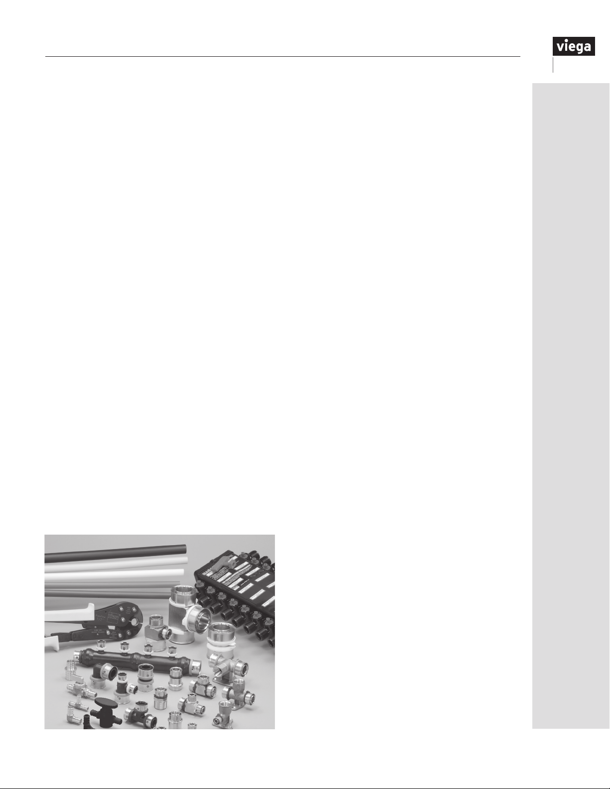
Viega PEX systems are the most complete potable
water solutions available on the North American
market. With tubing, fittings and distribution
manifolds, Viega provides everything you need for a
total plumbing system that is not only easy to install
but also helps reduce energy costs and water waste.
Viega provides the highest-quality PEX tubing with
the best UV and chlorine ratings in the industry. Viega
PEX Press fittings allow installers to make secure
press connections in less than seven seconds. With
Viega press technology, pressure testing can be
completed immediately after connections are made
without waiting for glues or solvents to dry or for
expansions to contract. Viega PEX Press fittings are
approved for potable water and hydronic heating
applications and are available in sizes ranging from
⅜" through 2" in both Zero Lead and high-grade
polymer materials. With a comprehensive 10-year
transferable limited warranty and unmatched quality in
the industry, Viega offers a complete system solution
for all your plumbing needs.
Do more with Viega
Viega press technology is consistent and reliable,
providing the same quality pipe connections every
time. Viega PEX Press polymer fittings incorporate the
Viega Smart Connect feature, which helps installers
identify unpressed connections easily. ViegaPEX
Ultra tubing and Viega PEX Press polymer fittings
are manufactured in the United States and provide
secure, reliable connections for residential and light
commercial projects, ranging from potable water to
snow melting applications.
A true innovator since 1899, Viega is at the forefront
of pipe joining technology. With personalized support,
efficient delivery processes and trustworthy quality,
no other manufacturer can provide the same level of
service. The global leader in plumbing, heating and
pipe joining systems, Viega is the name you can trust.
1.2 Viega PEX system concepts
Viega PEX is a high-quality, flexible PEX system for hot
and cold potable water distribution.
The Viega PEX plumbing system offers maximum
security thanks to press and full-circle crimp fitting
techniques. These fittings ensure the plumber
quick installation, suitability for use inall types
of applications at the construction site and vast
reductions in the required number of fittings and
necessary installation time.
The systems incorporate:
• ViegaPEX Ultra tubing: red, white, blue and black
cross-linked polyethylene tubing designed with
superior chlorine and UV resistance
• Black ViegaPEX Ultra tubing (¾" - 2"): UL 1821
listed for use in multipurpose one- and two-family
fire sprinkler systems per NFPA 13D
• Viega FostaPEX tubing: cross-linked polyethylene
with additional aluminum and polyethylene layers
to provide rigidity and form stability, available in
red or silver to differentiate hot water lines
• A range of Zero Lead bronze, Eco Brass or polymer
fittings for PEX Press and PEX Crimp fitting
systems
• Viega ManaBloc distribution system for use with
ViegaPEX tubing
• A range of inline, manifold and stop valves for
Viega PEX fitting systems
• Viega press tools and jaws for the PEX Press
fitting systems
• Viega crimp tools for the PEX Crimp fitting systems
IM-PF 724596 0416
5
Page 6

2 Codes, Standards and Certifications
2.1 Codes
The Viega PEX system is accepted by the following
model codes for use in potable hot and cold water
distribution systems.
ICC – International Code Council
IPC – International Plumbing Code
IMC – International Mechanical Code
IRC – International Residential Code
UPC – Uniform Plumbing Code
UMC – Uniform Mechanical Code
NSPC – National Standard Plumbing Code
HUD – Housing for Urban Development
NPCC – National Plumbing Code of Canada
NBCC – National Building Code of Canada
Check with your local Viega representative for code
compliance in your area.
2.2 Standards
ASTM — American Society for Testing and Materials
ASTM F876/F2023: Standard Specification for
Cross-linked Polyethylene (PEX) Tubing — This
standard contains nite dimensional requirements
for SDR9 PEX tubing in addition to burst, sustained
pressure, chlorine resistance and other relevant
performance tests at different water temperatures.
ASTM F877: Standard Specification for Crosslinked Polyethylene (PEX) Plastic Hot- and ColdWater Distribution Systems — This standard
contains performance requirements for SDR9 PEX
tubing and tting systems. The standard contains
nite dimensional requirements for tubing, in addition
to burst, sustained pressure and other relevant
performance tests at different water temperatures.
ASTM E84 — Standard Test Method for Surface
Burning Characteristics of Building Materials
ASTM E119 — Standard Test Method for Fire
Testing of Building Construction and Materials
NSF International
ANSI/NSF 14: Plastics Piping System Components
and Related Materials — This standard establishes
minimum physical and performance requirements for
plastic piping components and related materials. These
criteria were established for the protection of public
health and the environment.
ANSI/NSF 61: Drinking Water System
Components — Health Effects — This standard
establishesminimum health effects requirements for the
chemical contaminants and impurities that are indirectly
imparted to drinking water from products, components
and materials used in drinking water systems. This
standard does not establish performance or taste and
odor requirements for drinking water system products,
components ormaterials.
American Water Works Association (AWWA)
AWWA C904 — Cross-linked Polyethylene (PEX)
Pressure Pipe, ½" through 2" for Water Service
ISO — International Standards Organization
ISO 9001 — This standard is intended to establish,
document and maintain a system for ensuring
production output quality. ISO 9001 certication is a
tangible expression of a rm’s commitment to quality
that is internationally understood and accepted. All
PureFlow PEX Press ttings are manufactured in
ISO9001 certied facilities.
2.3 Certifications
PPI — Plastic Pipe Institute
TR 4 Listed Materials
Listing of Hydrostatic Design Bases (HDB), Strength
Design Bases (SDB), Pressure Design Bases (PDB)
and Minimum Required Strength (MRS) Ratings for
Thermoplastic Piping Materials or Pipe.
Pressure/Temperature Ratings:
•160 psi at 73.4 °F
•100 psi at 180 °F
•80 psi at 200 °F
ASTM E814 — Standard Test Method for Fire Test
of Through-Penetration Firestop Systems
6
NSF International
NSF-pw certification mark — Product meets all
applicable performance standards for pressure-rated
potable water applications required in ANSI/NSF
Standard 14 and complies with ANSI/NSF Standard 61
for health effects.
IM-PF 724596 0416
Page 7

cNSF®us pw-G — Product meets Zero Lead listing
meeting California AB 1953 and Vermont Act 193
CSA B137.5 — This standard species
requirements for thermoplastic pressure piping.
It includes reference publications, denitions,
abbreviations, general requirements for materials
and manufactured pipe and ttings, relevant test
methods, and marking requirements.
NSF U.P. Code — Product meets requirements of the
Uniform Plumbing Code™.
PEX 5306 — Tested and certied to the NSF-pw 5306
chlorine resistance rating for an end-use condition of
100% @ 140°F per ASTM F876, which is the highest
chlorine resistance rating available through ASTM.
When the product is marked with the PEX 5306
designation it afrms the product is approved for use in
continuous domestic hot-water circulation systems with
up to 140°F water temperatures and has a maximum
UV rating of six months.
Underwriters Laboratories Inc. (UL)
UL1821 — Standard for Safety for Thermoplastic
Sprinkler Pipe and Fittings for Fire Protection Service
(NFPA 13D systems only)
ANSI/UL 263 — Standard for Safety for Fire Tests for
Building Construction and Materials
Underwriters Laboratories of Canada Inc. (cUL)
CAN/ULC — S101 — Standard Methods of Fire
Endurance Tests of Building Construction and Materials
IAPMO R&T — International Association of
Plumbing and Mechanical Officials Research
andTesting
Certificate of Listing — Product meets the
requirements of the Uniform Plumbing Code™
ICC — ES — International Code Council —
Evaluation Services
ICC ES-PMG™ — Product complies with International
Plumbing Code
Note: Certications available at:
www.nsf.org
www.spec-direct.com (Intertek)
www.ul.com
www.canada.ul.com
2.4 Specifying Viega PEX Systems
Viega offers many tools to assist the specifying
engineer, engineer, contractor and installer to
ensure Viega PEX systems are properly designed
and installed. This can be done by referring to one
of the resources listed below:
• Engineering Specications are available at
www.viega.us
• Viega guide specications in Master Spec
format are available upon request at
1(800) 976-9819.
• Contact your local Viega eld sales
representative.
CAN/ULC — S102.2 — Standard Method of Test
for Surface Burning Characteristics of Flooring, Floor
Covering and Miscellaneous Materials and Assemblies
CAN/ULC — S115 — Standard Method of Fire Tests of
Firestop Systems
CAN/ULC/ORD/-C199P — Combustible Piping for
Sprinkler Systems
Check with your local Viega representative for further information or copies of above-mentioned listings and certications.
IM-PF 724596 0416
7
Page 8
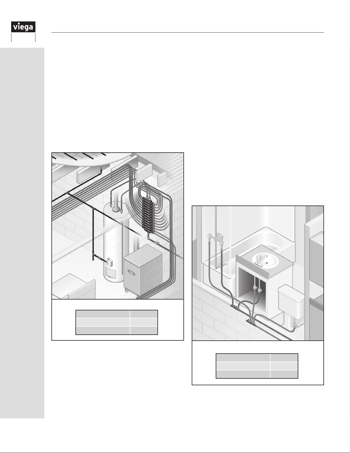
3 Viega PEX Installation Methods
There are three installation methods that Viega
recommends to help enhance your water
distribution systems performance by reducing
water waste and hot water delivery times. These
methods consist of the home run, combination and
branch and tee systems. The following sections
provide information to help select the best system
based on the application.
3.1 Home run systems
The Viega ManaBloc manifold system, also known
as a parallel or home run system, is a unique
method of plumbing that provides homeowners
water and energy savings and can reduce water
waste by up to 40% compared to traditional
systems.
• Better Control of the Plumbing System –
individual ¼-turn shutoff valves provide a
simple way of servicing a xture or adding on
to the system
3.2 Combination systems
A combination system uses multiple manifolds
combined with a branch-and-tee supply system.
These systems use small manifolds located
throughout a structure placed near each main
fixture group and are supplied by the main hot
and cold supply lines similar to the branch-andtee system. The manifolds branch multiple lines
from a common location in lieu of multiple tee
fittings spread throughout. This takes advantage
of benefits from both types of systems and helps
keep hidden fittings to a minimum.
• Ideal for areas with multiple xtures grouped
together
• Uses fewer connections behind walls
compared to branch and tee
Home Run Installation
Connections Low
Installation Time Medium
System Efciency High
Features that the Viega ManaBloc system offers its
customers over branch and tee plumbing systems
include:
• Faster Hot Water Delivery – properly sized
lines deliver hot water up to four times faster
• Dedicated lines to each xture use fewer
tting connections behind walls
• Balanced Water Delivery – multiple xtures
can be used simultaneously without
noticeable pressure or temperature changes
8
Combination Installation
Connections Medium
Installation Time Low
System Efciency Medium
IM-PF 724596 0416
Page 9
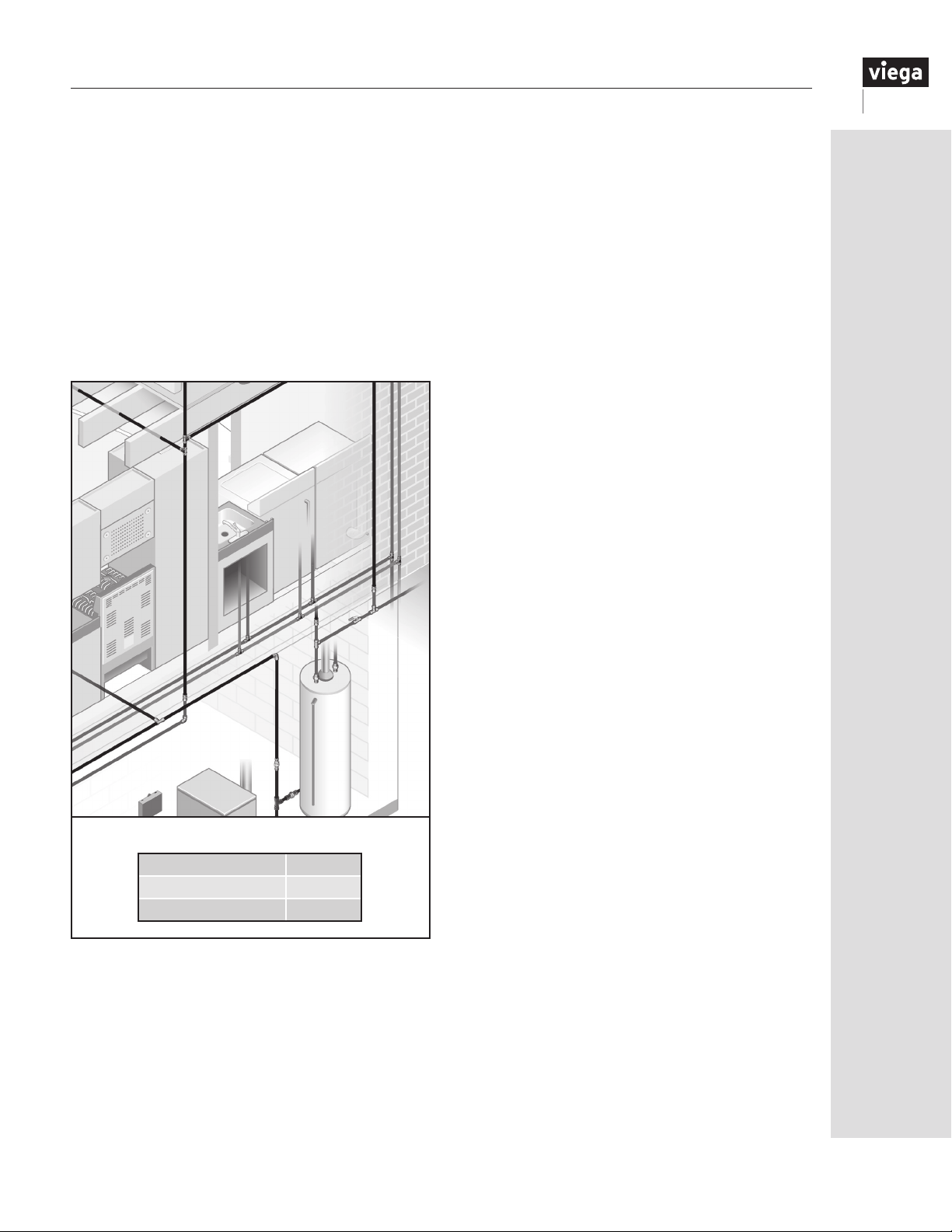
3.3 Branch and tee
This method of plumbing is commonly referred to
as a conventional plumbing system or branch-andmain systems.
This system uses a large-diameter “main” supply
line for both hot and cold water supplies that runs
throughout a structure to or near each fixture
group, with smaller “branch” lines teeing off the
main to supply each fixture.
• Ideal for condensed oor plans
• Less installation time
Branch-and-Tee Installation
IM-PF 724596 0416
Connections High
Installation Time Low
System Efciency Low
9
Page 10
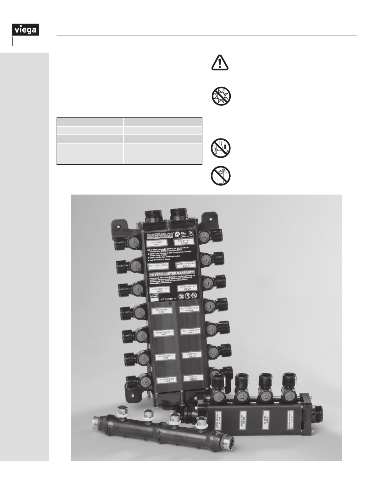
4 Viega Manifolds
Viega offers several different manifolds to meet a
variety of applications, whether it is a parallel water
distribution system or combination installation.
4.1 Viega manifold markings
Each Viega manifold is marked where space permits
with the following information:
Manufacturer VIEGA
ASTM Standard ASTM F877 / F1807 / F2159
Temperature Rating 180°F
Certications
NOTE: All manifolds may not be listed with each
organization shown.
®
, cNSF®us pw-G,
UPC
CSA B137.5,
ICC-ES PMG
™
1038
To maintain your warranty and be code
compliant, use only Viega-approved
fittings to connect ViegaPEX Ultra
tubing to the ManaBloc.
Viega polymer manifolds must be
protected from UV exposure, which can
damage them. In the event of incidental
UV exposure during storage, installation
and handling, combined exposure
of Viega polymer manifolds shall not
exceed 15 days.
Do not expose Viega products to any
foreign substance that includes but
is not limited to VOC (volatile organic
chemical) compounds, paints, solvents,
glues, cleaners and disinfectants. Viega
products that are exposed to these
types of substances are at risk of having
failures (leaks).
10
IM-PF 724596 0416
Page 11
5 Viega PEX Press Fittings
Viega PEX Press ttings are available in Zero
Lead Bronze and polymer and include a factoryassembled, stainless steel sleeve with three
viewing holes and a tool locator ring to ensure a
proper press connection. The following design
criteria make Viega PEX Press ttings ideal for use
in potable water applications:
• High corrosion resistance
• Excellent strength properties
• Resistant to stress corrosion
• Superior wear properties
• Compatible with all materials
All Viega PEX tubing, fittings and manifolds are NSF
certified for use in potable water systems.
5.1 Viega PEX Press bronze
Viega PEX Press bronze ttings are manufactured
from a high-quality Zero Lead material specically
designed for press technology meeting or
exceeding all manufacturing requirements.
5.2 Viega PEX Press polymer
Viega PEX Press polymer ttings are
manufactured from Radel R® and incorporate
the Viega Smart Connect feature.
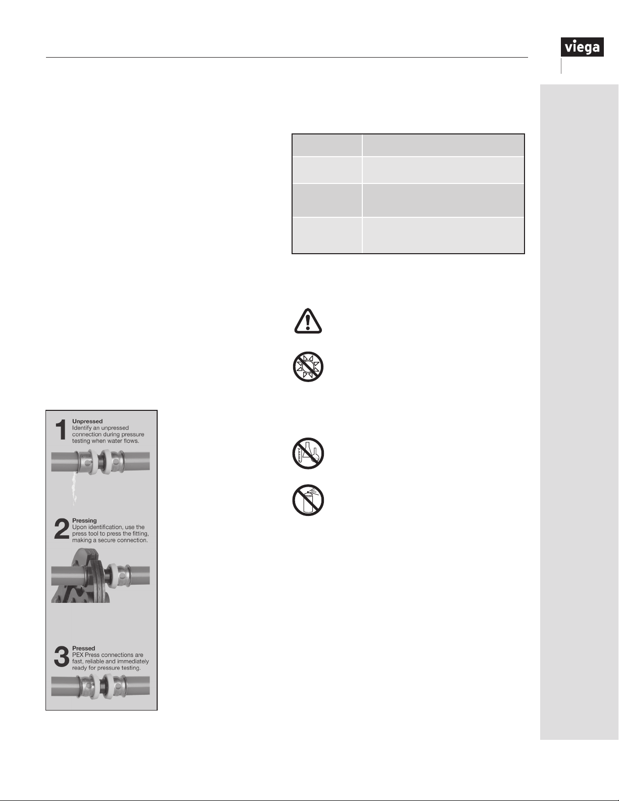
5.2.1 Viega Smart Connect feature
The Viega PEX Press
Polymer tting system
incorporates the Viega
Smart Connect feature,
which is designed to
identify unpressed
connections by
intentionally leaking
under test pressures of
0.5 psi to 100 psi. This
can be visually identied
by water leaking from
the unpressed tting
joint. If testing with
compressed air, it is
necessary to use an
approved leak-detect
solution (see “Leak
detection” on Page
61), applied to each
connection, to identify
a suspected leak.
Press any connections
that may have been
missed and/or replace
connections found to be
Figure 5.1 Smart
Connect Feature
in question. Repeat the
system pressure test.
5.3 Viega PEX Press fitting markings
Each Viega PEX Press fitting is marked where space
permits with the following information:
Manufacturer VIEGA
ASTM Standard ASTM F877
Temperature
Rating
Certications
NOTE: All ttings may not be listed with each
organization shown.
Use only Viega stainless steel attached
PEX Press sleeves and press tools with
Viega PEX Press fittings.
Viega PEX Press polymer fittings must
be protected from UV exposure, which
can damage them. In the event of
incidental UV exposure during storage,
installation and handling, combined
exposure of PEX Press fittings shall not
exceed 15 days.
Do not expose Viega products to any
foreign substance that includes but
is not limited to VOC (volatile organic
chemical) compounds, paints, solvents,
glues, cleaners and disinfectants.
Viega products that are exposed to
these types of substances are at risk of
having failures (leaks).
180°F (potable)
200°F (hydronic heating)
®
cNSF
us pw-G, CSA B137.5
®
UPC
or UP Code, cULus
ICC-ES PMG™ 1038 / 1015
®
IM-PF 724596 0416
11
Page 12
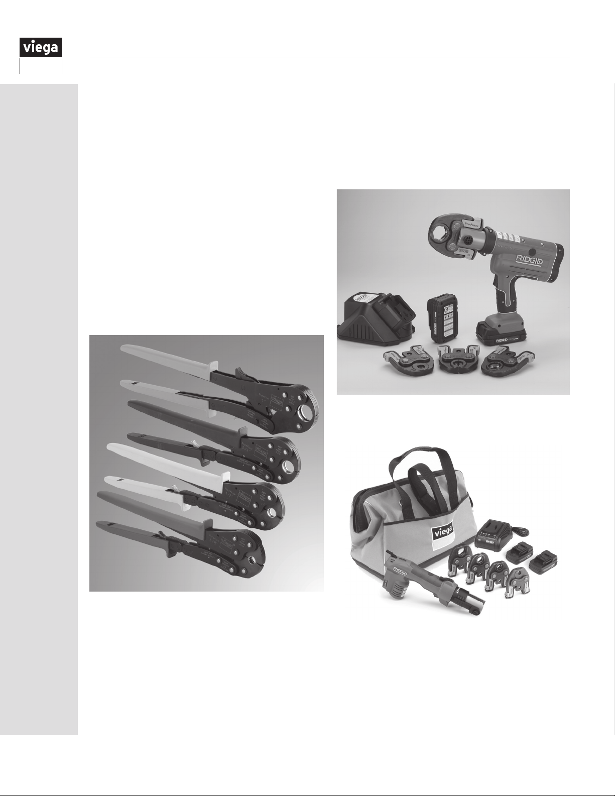
5.4 PEX Press tools
5.4.1 PEX Press hand tools
The Viega PEX Press connection must always be
carried out with the aid of a Viega PEX Press tool.
The hand tool incorporates a forced compression
mechanism to complete a secure connection each
time. A ratchet inside the tool prevents the tool
from being opened until the proper force has been
applied to the press sleeve. A safety release screw
allows the tool to be opened at any time, but any
connection made without full tool compression
must be repressed. The tool handles are color
coded to match the PEX Press tool locator rings.
The reduced grip feature permits one-handed
operation, making the Viega PEX Press system
ideal for tight spaces and awkward locations. The
compression of the tool also allows press connections
to be made in temperatures as low as -4°F.
5.4.2 PEX Press power tools
The Viega PEX Press connection may also be carried
out with a Viega power tool. These RIDGID tools are
designed to make the same consistent press as the
Viega PEX Press hand tools. The compression of the
tool also allows press connections to be made in
temperatures as low as 23°F.
Compact Power Tool
RP-200-B Kit
12
IM-PF 724596 0416
Page 13
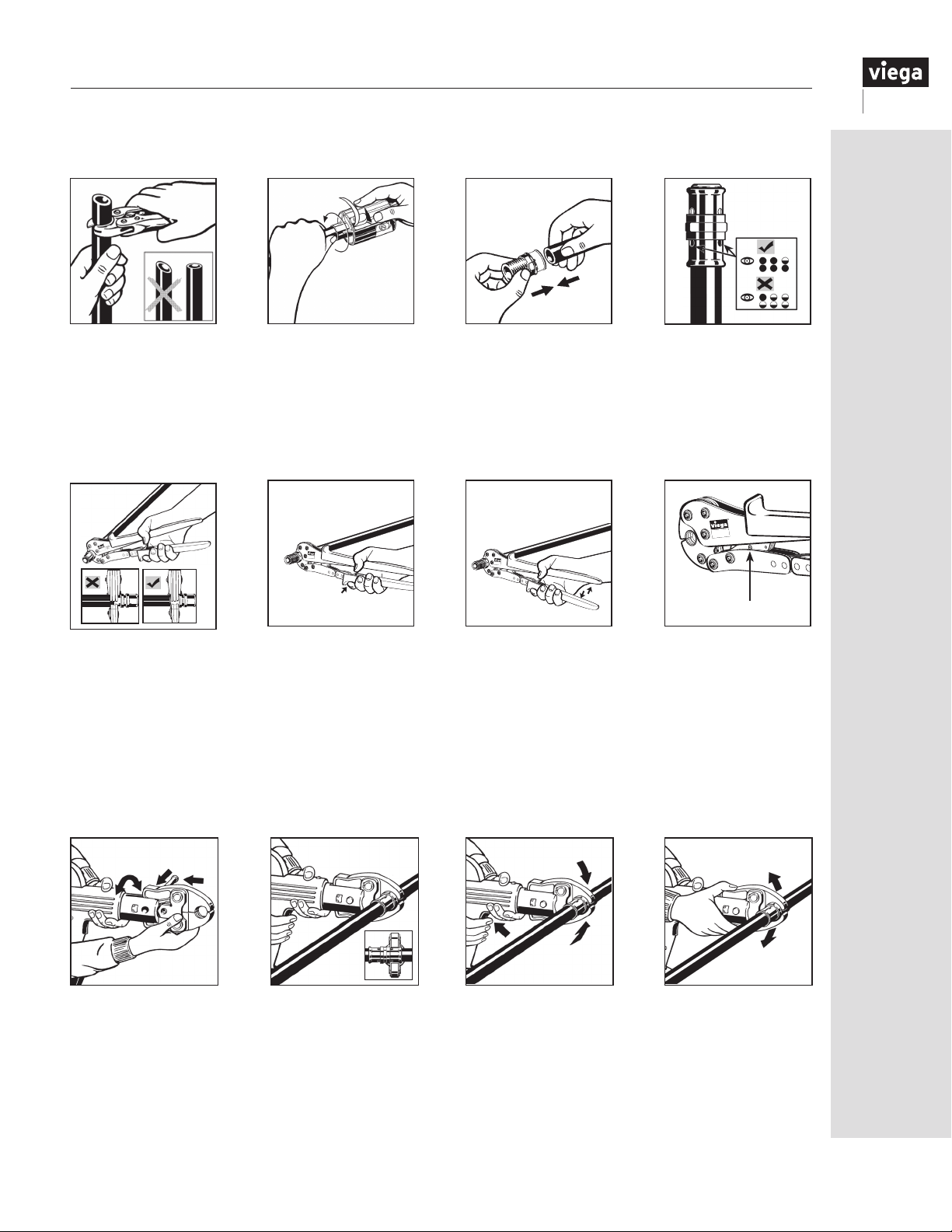
5.5 Making a Viega PEX Press connection with hand tool
5.5.1 Trimming and inserting the tubing
1 2
1.
Square off tubing to proper length. Uneven, jagged or irregular cuts will produce unsatisfactory connections.
2. If using FostaPEX tubing, insert into prep tool, push and turn until no resistance is felt. If using ViegaPEX
Ultra, continue to Step 3.
3. Insert PEX Press tting with attached sleeve into tubing and engage fully.
4. Ensure full tubing insertion at view holes in attached press sleeve. Full insertion means tubing must be
completely visible in at least two view holes and partially visible in the third.
5.5.2 Pressing with a hand tool
5
6
Pure
Flow
1/2”
3
7
8
Flow
Pure
1/2”
Pure
Flow
1/2”
4
Turn screw for
emergency release.
5. Position press tool perpendicular over press sleeve, resting it against the tool locator ring.
Note: The tool locator ring must be in the factory-installed position while making a press to provide a
consistent leakproof PEX press connection. It may be necessary to rotate the tool locator ring to avoid
interference between the ring and tool.
6. Close handles, using trigger to reduce grip span if desired.
7. Extend handle and continue ratcheting until automatic tool release occurs at proper compression force.
8. Warning: The PEX press connection is not leakproof when the tool has been opened by emergency release.
The tool locator ring must be present to ensure a proper PEX Press connection.
5.5.3 Pressing with a power tool
5 7
86
5. Insert the appropriate Viega PEX Press jaw into the press tool and push in the holding pin until it locks.
6. Open jaw and position perpendicular over press sleeve, resting it against the tool locator ring.
Note: The tool locator ring must be in the factory-installed position while making a press to provide a
consistent leakproof PEX press connection. It may be necessary to rotate the tool locator ring to avoid
interference between the ring and tool.
7. Start pressing process; hold the trigger until the jaw has automatically released.
8. When press connection is complete, open and remove jaw.
9. Warning: The tool locator ring must be present to ensure a proper PEX Press connection.
IM-PF 724596 0416
13
Page 14
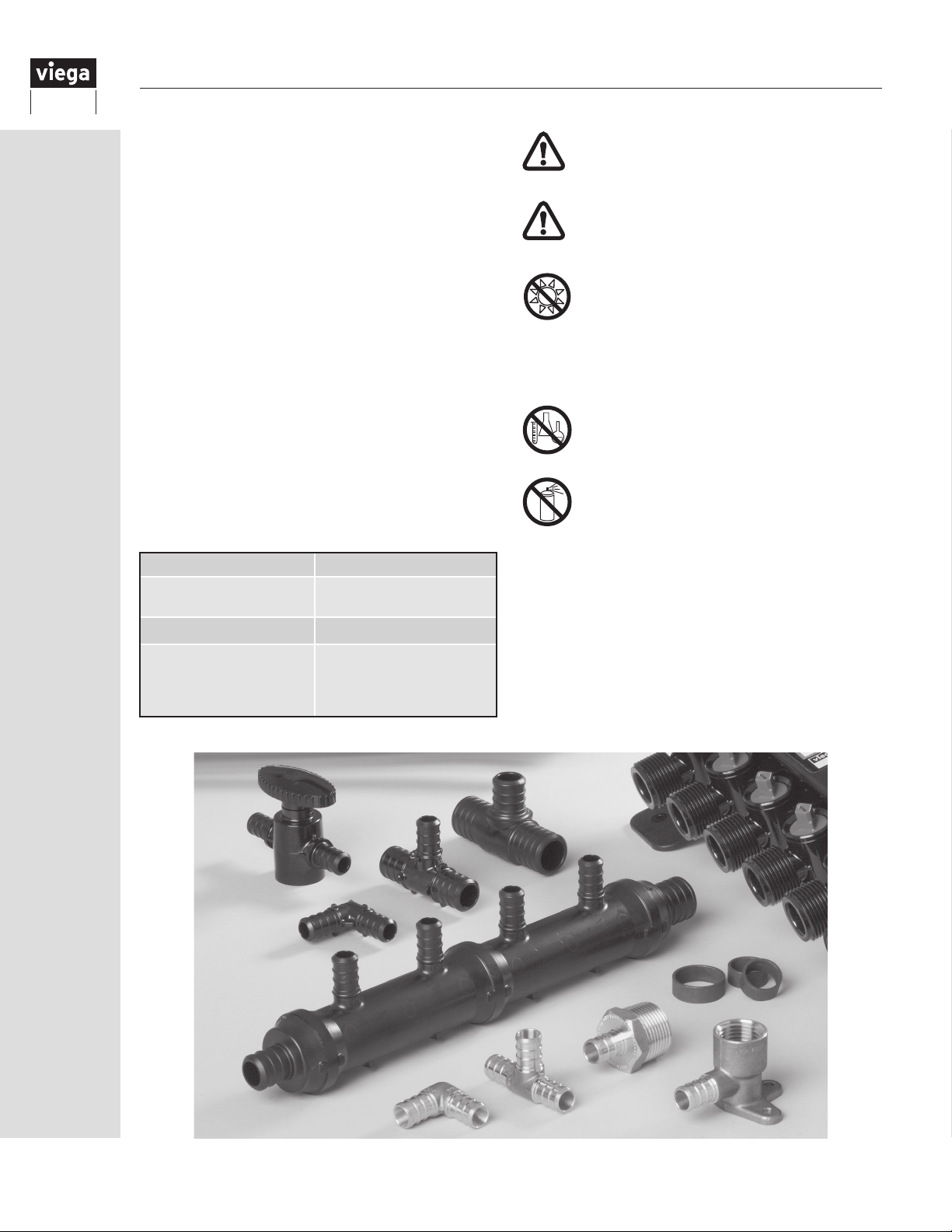
6 Viega PEX Crimp Fittings
Viega PEX Crimp ttings are in metallic or polymer
congurations. The following design criteria make
Viega PEX Crimp ttings ideal for use in potable
water applications.
• Excellent strength properties
• Corrosion resistant
• Fast installation
All Viega PEX tubing, ttings and manifolds are NSF
certied for use in potable water systems.
6.1 Viega PEX Crimp Eco Brass fittings
PEX Crimp Eco Brass ttings are manufactured
from a high-grade Zero Lead alloy known for its
superior properties.
6.2 Viega PEX Crimp PolyAlloy fittings
PEX Crimp PolyAlloy ttings are manufactured
from a performance-grade polymer (Acudel® and/
or Radel-R®) with
excellent chlorine- and corrosion-
resistant properties.
6.3 Viega PEX Crimp fitting markings
Each Viega PEX Crimp tting is marked where space
permits with the following information:
Manufacturer VIEGA
ASTM Standard
Temperature Rating 180°F
ASTM F1807 (metallic)
F2159 (polymer)
Use only ASTM F1807 copper crimp rings
and full-circle crimp tools with Viega PEX
Crimp fittings.
NOT for use with FostaPEX tubing.
Viega PEX Crimp PolyAlloy fittings
must be protected from UV exposure,
which can damage them. In the event of
incidental UV exposure during storage,
installation and handling, combined
exposure of PEX Crimp PolyAlloy fittings
shall not exceed 15 days.
Do not expose Viega products to any
foreign substance that includes but
is not limited to VOC (volatile organic
chemical) compounds, paints, solvents,
glues, cleaners and disinfectants. Viega
products that are exposed to these
types of substances are at risk of having
failures (leaks).
®
, or U.P. Code, NSF-pw,
UPC
Certications
Note: All ttings may not be listed with every organization shown.
CSA B137.5, cNSF
ICC-ES PMG
™
1038
®
us pw-G,
14
IM-PF 724596 0416
Page 15
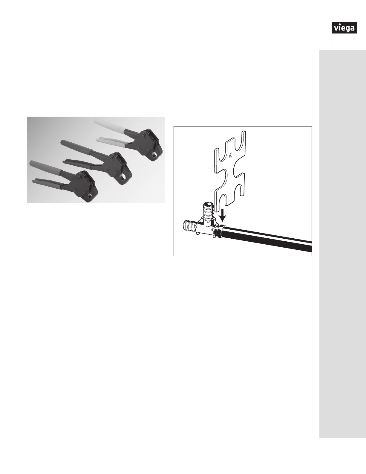
6.4 The Viega PEX Crimp hand tools
The Viega PEX Crimp connection must always
be carried out with the aid of a Viega PEX Crimp
tool. There are multiple congurations of Viega
PEX Crimp tools that are ideal for tight spaces and
awkward locations. The compression of the tool
also allows for crimp connections to be made in
temperatures as low as -30°F.
A caliper (GO/NO GO gauge) is provided to check
the calibration of the crimp tool. A crimp is good
if the GO gauge ts over the ring and the NO GO
gauge does not.
At least one connection should be checked at the
beginning and end of each day to ensure proper
crimps have been made. Most crimp tools can be
recalibrated. Please refer to tool instructions on the
next page.
A caliper (GO/NO GO gauge) is provided to
check the crimp tool calibration.
IM-PF 724596 0416
15
Page 16
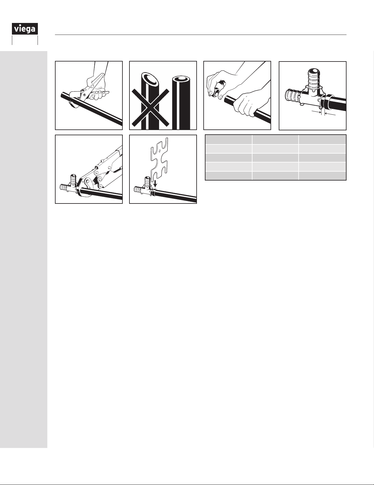
6.5 Making a Viega PEX Crimp connection
1 2 3
1
/8” to ¼”
5
90°
6
1. The tubing should be cut squarely and evenly without burrs. Uneven, jagged or irregular cuts will
produce unsatisfactory connections.
2. The diagram shows a correctly cut tube compared with an incorrectly cut tube.
3. Slide the crimp ring onto the tubing and insert the tting into the pipe to the shoulder or tube stop.
4. Position the ring ⅛" to ¼" from the end of the tubing.
5. The ring must be attached straight. Center the crimping tool jaws exactly over the ring. Keep the tool
at 90° and close the handles completely. DO NOT CRIMP TWICE.
6. When checking crimp connections with a caliper (GO/NO GO gauge), push the gauge
STRAIGHT DOWN over the crimped ring. NEVER slide the gauge in from the side. Do not attempt
to gauge the crimp at the jaw overlap area. The overlap area is indicated by a slight removal of the
blackening treatment. A crimp is acceptable if the GO gauge ts the ring and the NO GO does not.
A crimp is unacceptable if the GO gauge does not t the ring or the NO GO gauge does t. An
incorrect crimp must be cut out of the tubing and replaced. If you check the crimp connections with a
micrometer or caliper, use the dimensions shown in the chart above.
RING SIZE MINIMUM MAXIMUM
⅜" 0.580" 0.595"
½" 0.700" 0.715"
¾" 0.945" 0.960"
1" 1.175" 1.190"
Table 6.1 Crimp Diameter Dimensions. Crimp outside diameters
should fall within these dimensions when measured with a
micrometer or caliper.
4
16
IM-PF 724596 0416
Page 17
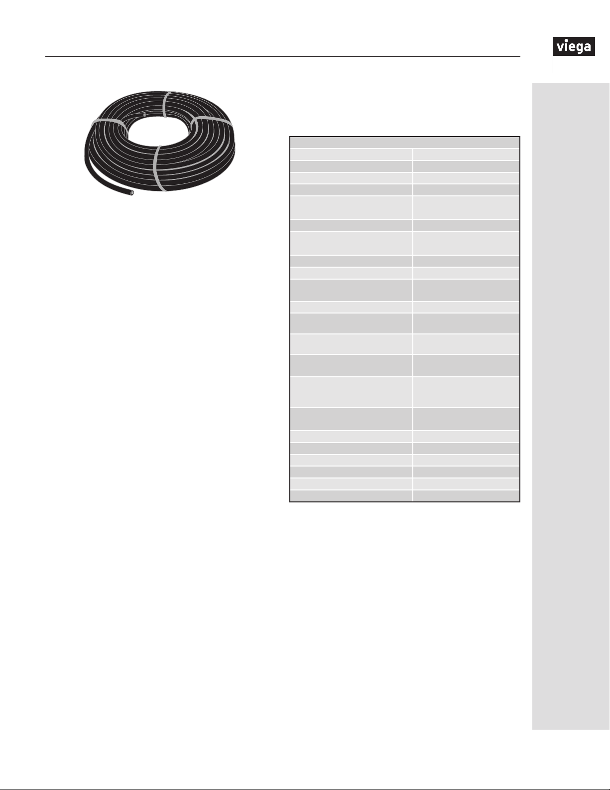
ViegaPEX Ultra
cross-linked polyethylene is the ideal
tubing choice for potable water systems. In addition,
the smooth walls of ViegaPEX Ultra tubing are resistant
to corrosion and scaling.
7.1 ViegaPEX Ultra properties and performance
Linear Expansion Coefficient:
• 1.1 inch per 100 feet per 10°F
Temperature and Pressure Ratings:
• 180°F at 100 psi
• 73.4°F at 160 psi
UV Resistance:
• Maximum exposure 6 months
Chlorine Resistance:
• PEX 5306 — end-use condition of 100% at 140°F
(approved for continuous domestic hot water
circulation systems)
Bend Radius:
• ViegaPEX Ultra can be easily bent by hand, or with
the use of Viega-approved bend supports toaradius
as small as five times tubing outerdiameter.
7 ViegaPEX Ultra Tubing
7.2 Tubing markings
ViegaPEX Ultra tubing is marked every five feet with
the following representative information. See Table 7.1.
Print Line Markings
Length Marker 000 feet
Company Viega
Product Name ViegaPEX™ Ultra
Nominal Tubing Size ½"
Standard Dimension
Ratio Tube Size
Material Designation Code PEX 5306
Temperature & Pressure Rating
NSF Listing (Potable) cNSF
NSF Chlorine Listing CL5
ASTM
Tubing Standards Certification
Canadian Standard Assoc CSA B137.5
Fittings System Compatibility
IAPMO Listing UPC
UL Listing Rating*
Plenum Rating**
Fire Resistance Ratings
ICC Listing ES-PMG
AWWA Listing C904
HUD Listing MR 1276
Manufacturer’s Date Code 1/1/2010
Material Code X14.2
Country of Manufacture Made in the USA
Table 7.1
* ¾" through 2" Black ViegaPEX Ultra only
** 2" and smaller tube sizes when wrapped with ½" - 1" thick E84 rated
insulation, ½" and smaller with no insulation per ULC S102.2 listing.
Tubing may include fitting connections when wrapped.
SDR 9 CTS
(copper tube size)
100 psi @ 180F
160 psi @ 73F
®
us-pw
F876/F877
PureFlow - ASTM F877/
F1807/F2159
®
cULus 3SAV UL1821
130 psi @ 120F
FS/SD 25/50
ASTM E84
CAN/ULC S102.2
CAN/ULC S101
ANSI/UL 263
™
- 1038
IM-PF 724596 0416
17
Page 18
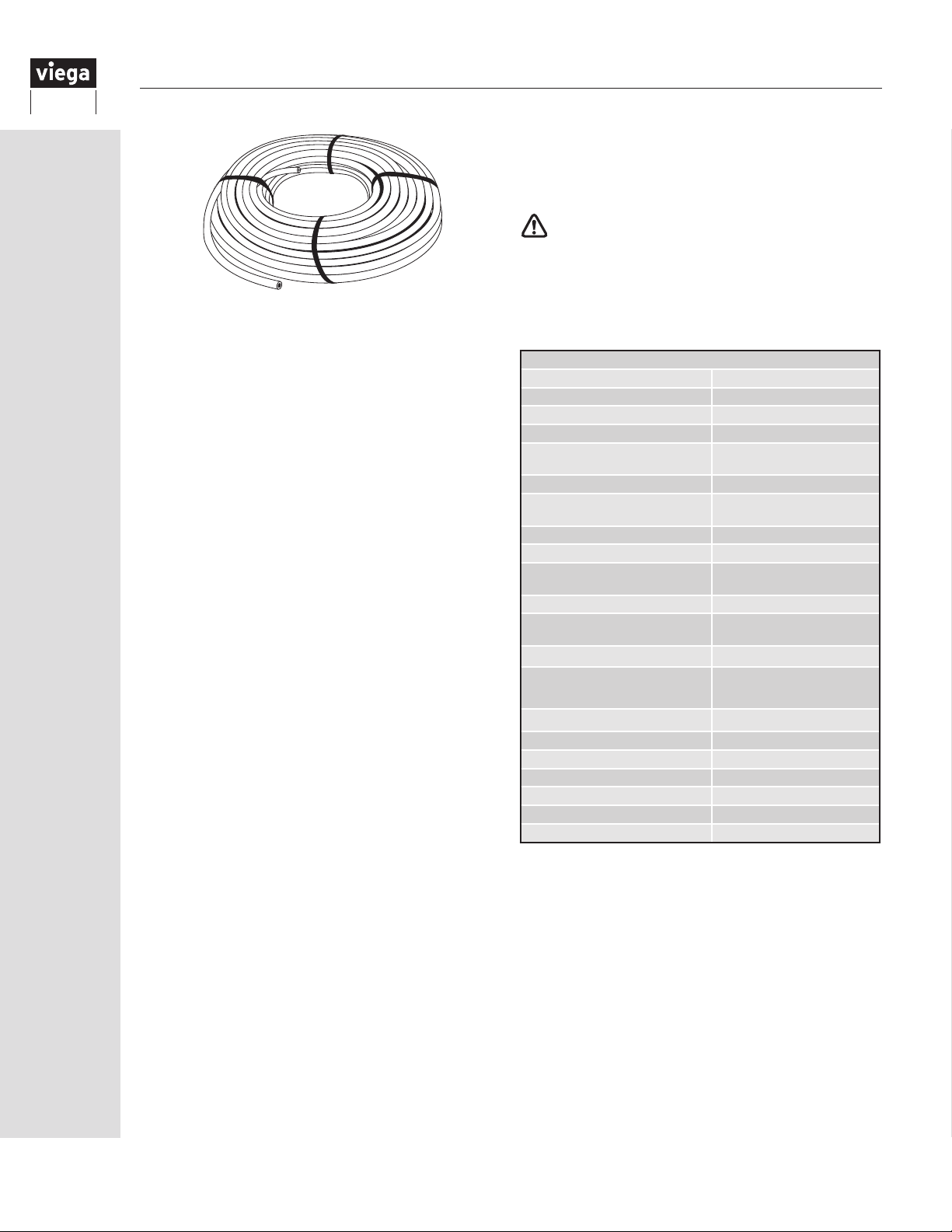
8 Viega FostaPEX Tubing
Viega FostaPEX tubing is the ideal companion for the
Viega PEX plumbing system. This tubing can be easily
bent by hand like the ViegaPEX Ultratubing but holds
its shape after bending (combining the benefitsof both
rigid and flexible tubing). The result is fewer fittings
and bend supports and less labor. A unique feature of
FostaPEX is that the inner layer is fully dimensioned
Black ViegaPEX Ultra tubing. The aluminum and
outer PE layers surround the inner PEX tubing. This
construction allows the inner layer alone to meet all
temperature and pressure requirements of the system.
Using theprep tool to remove the outer layers allows
the use of the standard Viega PEX Press bronze and
polymer fitting systems, which reduces tooling costs for
the contractor and simplifies connections.
8.1 FostaPEX properties and performance
Linear Expansion Coefficient:
• 0.16 inch per 100 feet per 10°F
Temperature and Pressure Ratings:
• 200°F at 80 psi *
• 180°F at 100 psi
• 73.4°F at 160 psi
*For non-potable hydronic heating systems only
UV Resistance:
• Maximum exposure six months based on FostaPEX’s
fully dimensioned black PEX core. Extended
exposure due to the outer aluminum layer (do not
install where permanently exposed to sunlight).
Chlorine Resistance:
• PEX 5306 - end-use condition of 100% at 140°F
(approved for continuous domestic hot water
circulation systems)
Bend Radius:
• FostaPEX tubing can be bent to a radius of 3.5 times
tubing outer diameter with the use of a Viega tubing
bender.
Not for use with PEX Crimp fittings.
8.2 Tubing markings
FostaPEX tubing is marked every five feet with the
following representative information. See Table 8.1.
Print Line Markings
Length Marker 000 feet
Company Viega
Product Name FostaPEX
Nominal Tubing Size ½"
Standard Dimension
Ratio Tube Size
Material Designation Code PEX 5306
Temperature & Pressure Rating
NSF Listing (Potable/Heating) cNSF
NSF Chlorine Listing CL5
ASTM
Tubing Standards Certification
Canadian Standard Assoc CSA B137.5
Fittings System Compatibility
IAPMO Listing UPC
Plenum Rating*
Fire Resistance Ratings
ICC Listing ES-PMG
AWWA Listing C904
HUD Listing MR 1276
Manufacturer's Date Code 1/1/2010
Material Code X18.1
Country of Manufacture Made in the USA
* 2" and smaller tube sizes when wrapped with ½" - 1" thick E84 rated
insulation, ½" and smaller with no insulation per ULC S102.2 listing.
Tubing may include fitting connections when wrapped.
SDR 9 CTS
(copper tube size)
100 psi @ 180F
160 psi @ 73F
F876/F877
PureFlow
ASTM F877
FS/SD 25/50
ASTM E84
CAN /ULC S102.2
CAN/ULC S101
ANSI/UL 263
Table 8.1
®
®
us-pw-rfh
®
™
- 1015,1038
18
IM-PF 724596 0416
Page 19
9 Viega PEX System Design and Sizing
9.1 ManaBloc
The general sizing information shown may be
appropriate for many ManaBloc installations. These
recommendations are based on ow rates of typical
xtures that require 8 psi residual pressure.
The length of distribution tubing run between the Viega
ManaBloc and each xture shall be 60 feet or less
to maximize optimal performance of the ManaBloc
system. Exceeding this recommended distance affects
the system’s ability to efciently deliver hot water,
lengthening the time it takes for hot water to reach the
xture as well as increasing water waste.
9.1.1 Supply and distribution line sizing
The best water and energy savings of a ManaBloc
system are realized when distribution lines are sized
according to the xture demand and the length of
the individual line. Viega recommends the following
tube sizing:
Typical supply line size:
•
¾" up to 2½ baths
•
1" up to 4½ baths
Typical distribution line size:
•
⅜" up to 2½ GPM xture ow requirement
(lavs, toilets, bidets, bar sinks, kitchen sinks,
dishwashers)
•
½" up to 4 GPM xture ow requirement (hose
bibbs, tubs, showers, washing machines, whirlpool
baths, soaking tubs, etc.)
Consult the xture manufacturer’s literature to
determine the actual ll rate and residual pressure
requirements for distribution line size. In addition,
conrm with local Authority Having Jurisdiction (AHJ)
for acceptable PEX tubing size.
Hose Bibb Note: If a hose bibb is primarily for
irrigation purposes, it should be supplied from the
main service line prior to the ManaBloc.
A Viega PEX Press and PEX Crimp ManaBloc come
with ½" ports that are designed to t both ⅜" and ½"
PEX port adapters.
Design factors for installing a home run system
Water heater placement
The Viega ManaBloc should be as close as possible
to the water heater to minimize extra water from being
stored in the larger hot water supply lines between the
ManaBloc and water heater.
Proper water distribution line sizing to each fixture
This is crucial for overall system performance. If you
oversize a distribution line to a fixture (½" PEX line
supplying a sink instead of a ⅜" PEX line) you are
essentially doubling the volume of water being stored
in that line. It can take roughly twice as long to purge
an oversized line compared to a properly sized line.
The fixture is what dictates water flow (federally
mandated, governed by code). The tubing applies a
friction loss dictated by its size and length. Therefore,
as long as you do not undersize a distribution line
or run it excessive distances (60 feet or greater), the
system will perform properly, maintaining sufficient
pressure and flow.
The length of a distribution line run to
each fixture
This is just as important as properly sizing each
distribution line. Length of a distribution line run can
drastically affect the performance of a Viega ManaBloc
system. The longer the line is, the more water being
stored within it. Therefore, it will take longer to purge
it out before hot water can reach the fixture. The
ManaBloc should be located somewhat central to your
fixture groups, keeping within 60 feet or less of each
fixture for maximum performance.
If this cannot be accomplished with one ManaBloc,
multiple ManaBlocs may be required. Place one at
each end of the home to split the distribution line
distance between them. (See “12.5 Multiple ManaBloc
installations” on Page 30).
9.1.2 Plumbing code compliance (home run / parallel systems)
The Viega ManaBloc system is listed to ASTM F876/
F877 standards for cross-linked polyethylene (PEX)
distribution systems. The below model plumbing
codes recognize and allow the use of PEX distribution
systems:
• International Plumbing Code (IPC)
• Uniform Plumbing Code (UPC)
• National Plumbing Code (NPC)
Sizing of Parallel Water Distribution Systems
(ManaBloc) is addressed in these model plumbing
codes under their respective water supply and
distribution sections. The Viega ManaBloc is also
IAPMO (UPC) and ICC-ES PMG listed for use with
and ½" PEX tubing sizes for water distribution.
⅜"
The longer the hot water supply line is, the greater
the volume of water needed to purge through that
line and faucet before hot water is available.
creates water waste and longer hot water delivery
times.
IM-PF 724596 0416
This
19
Page 20
9.2 Combination systems
PEX combination systems can be sized in a similar
manner as a typical branch-and-tee system.
Refer to your local or model plumbing code for
the required tube and manifold sizing based on
the system demand (Water Service Fixture Units,
WSFU). If low service pressure is present, Viega
provides the equivalent feet of PEX tubing factors
for PEX ttings to ensure any additional pressure
drop is accounted for in your design.
Design factors for installing combination systems
Design the layout as condensed as possible
Keep the main hot supply line close to the fixture
groups with the branch lines shorter than six feet.
This will help provide hot water in a reasonable
amount of time with less wasted water.
The limiting factor for installers to accomplish an
optimal design is how spread out the fixture groups
are within the structure.
9.3 Branch-and-tee systems
The same general sizing practices can be applied
to a PEX branch-and-tee system as with any codeapproved piping material. Refer to your local or
model plumbing code for proper tube sizing.
Design factors for installing branch-and-main
systems
Just like the combination system, condensed floor
plan layouts are preferable to minimize the length and
the amount of water stored in the main supply line,
minimizing the amount of water purged before hot
water reaches the fixtures. These systems can also
suffer from fluctuating pressure during multiple fixture
use.
If the fixture groups are not condensed, a branch-andmain system will have slow hot water delivery times
and substantial water waste.
If there is a floor plan that incorporates stacked or
back-to-back fixture groups, a combination system
can be an effective alternative to a parallel system.
20
IM-PF 724596 0416
Page 21
10 System Sizing and Calculations
10.1 General
Viega PEX systems should be designed following standard plumbing engineering practice. Follow local codes to
determine minimum tubing size and required xture pressures.
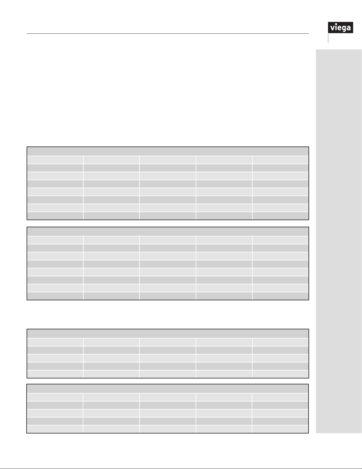
Pressure drop through ttings can be estimated from the charts below. Values are expressed in equivalent length
of PEX, so add the values for the relevant ttings to the length of tubing in the run, and then determine the total
pressure drop from the charts on the following page.
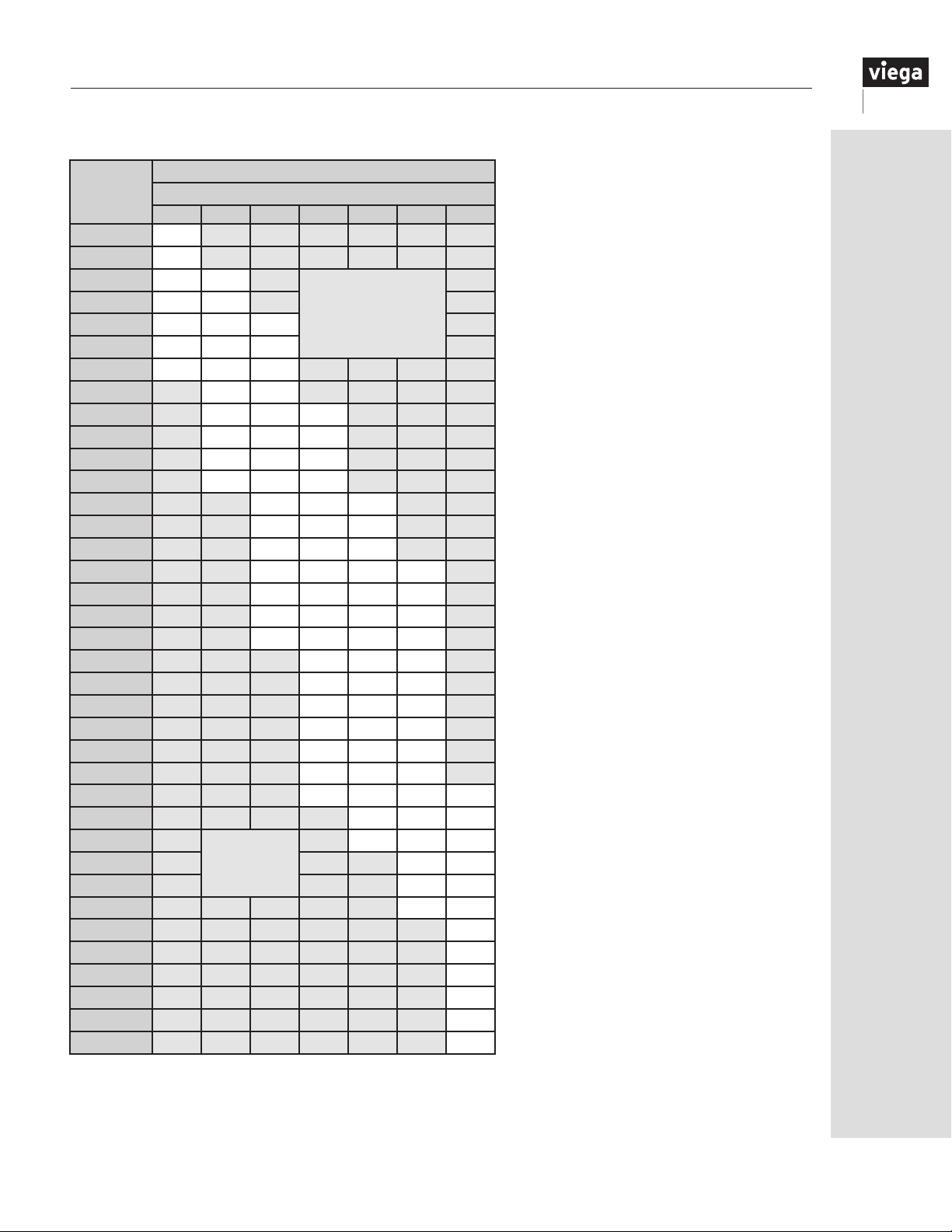
To determine the pressure drop through runs of ViegaPEX Ultra and FostaPEX tubing, refer to the pressure drop
chart on the following page. For a known ow rate, tubing size and tubing length, the pressure drop through the
run can be easily determined.
10.2 Viega PEX fittings
10.2.1 Viega PEX Press friction loss — equivalent feet of SDR9 PEX tubing
PEX Press Bronze Fittings
Size Coupling Elbow Tee Run Tee Branch
⅜" 2.9 9.2 2.9 9.4
½" 2.0 9.4 2.2 10.4
¾" 1.0 8.0 1.0 9.0
1" 1.0 10.0 2.0 10.0
1¼" 2.0 11.0 2.0 11.0
1½" 2.0 13.0 2.0 12.0
2" 1.0 19.0 2.0 18.0
PEX Press Polymer Fittings
Size Coupling Elbow Tee Run Tee Branch
⅜" 4.5 14.3 6.5 14.7
½" 2.6 12.6 3.9 14.0
¾" 2.5 18.9 3.6 19.1
1" 3.1 17.7 3.8 18.4
1¼" 4.0 18.6 6.4 18.7
1½" 5.2 29.4 7.9 28.3
2" 8.9 36.4 10.2 37.5
10.2.2 Viega PEX Crimp friction loss — equivalent feet of SDR9 PEX tubing
PEX Crimp Eco Brass Fittings
Size Coupling Elbow Tee Run Tee Branch
⅜" 2.9 9.2 2.9 9.4
½" 2.0 9.4 2.2 10.4
¾" 0.6 9.4 1.9 8.9
1" 1.3 10.0 2.3 11.0
PEX Crimp PolyAlloy Fittings
Size Coupling
⅜" 10.9
½" 7.1
¾" 4.8
1" 4.5
Elbow Tee Run Tee Branch
22.3 N/A N/A
16.5 7.2 17.9
17.4 6.6 17.7
18.0 6.0 17.0
IM-PF 724596 0416
21
Page 22
10.3 ViegaPEX Ultra tubing
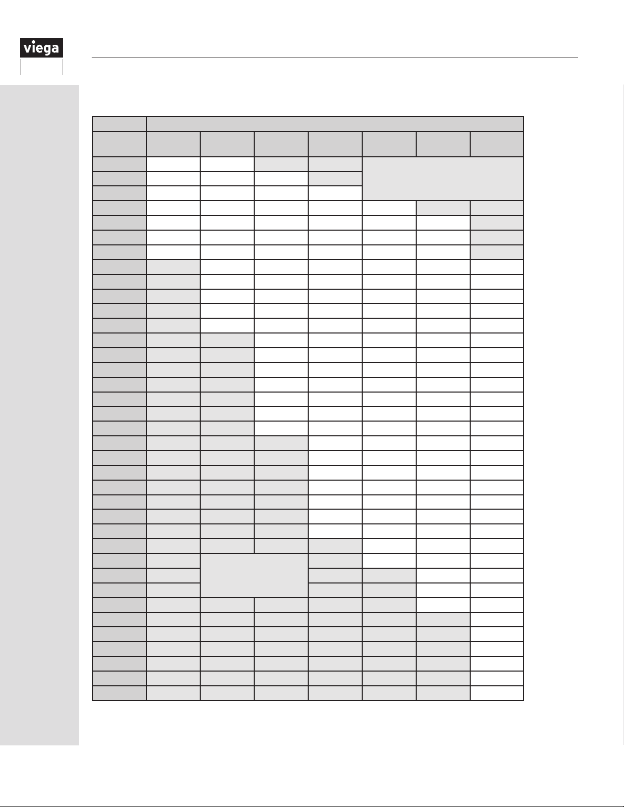
10.3.1 Flow Velocity Table
Flow Velocity ft/sec
Flow Rate
GPM
0.5 1.7 0.9
1.0 3.3 1.8 0.9 0.5
1.5 5.0 2.7 1.4 0.8 0.6
2.0 6.7 3.6 1.8 1.1 0.7 0.5
2.5 8.3 4.5 2.3 1.4 0.9 0.7
3.0 10.0 5.4 2.7 1.6 1.1 0.8
3.5 6.3 3.2 1.9 1.3 0.9 0.5
4.0 7.2 3.6 2.2 1.5 1.1 0.6
4.5 8.1 4.1 2.5 1.7 1.2 0.7
5.0 9.1 4.5 2.7 1.8 1.3 0.8
6.0 10.9 5.4 3.3 2.2 1.6 0.9
7.0 6.4 3.8 2.6 1.8 1.1
8.0 7.3 4.4 2.9 2.1 1.2
9.0 8.2 4.9 3.3 2.4 1.4
10.0 9.1 5.5 3.7 2.6 1.5
11.0 10.0 6.0 4.0 2.9 1.7
12.0 10.9 6.6 4.4 3.2 1.8
13.0 11.8 7.1 4.8 3.4 2.0
14.0 7.7 5.1 3.7 2.2
15.0 8.2 5.5 4.0 2.3
16.0 8.8 5.9 4.2 2.5
17.0 9.3 6.3 4.5 2.6
18.0 9.9 6.6 4.8 2.8
19.0 10.4 7.0 5.0 2.9
20.0 11.0 7.4 5.3 3.1
25.0 9.2 6.6 3.8
30.0
35.0 9.2 5.4
40.0 10.6 6.2
45.0 11.9 6.9
50.0 7.7
55.0 8.5
60.0 9.2
65.0 10.0
70.0 10.8
75.0 11.5
⅜ ½ ¾ 1 1¼ 1½ 2
Velocity < 0.5 ft/sec0.75 2.5 1.4 0.7
11.0 7.9 4.6
Velocity > 12 ft/sec
22
IM-PF 724596 0416
Page 23
10.3.2 Pressure Loss Table
60°F (16°C) Water
Flow Rate
GPM
0.5 2.0
0.75 4.1
1.0 7.0 1.6
1.5 14.9 3.4
2.0 25.4 5.8 1.1
2.5 38.5 8.7 1.6
3.0 53.9 12.2 2.3
3.5 16.2 3.0
4.0 20.8 3.9 1.1
4.5 25.8 4.8 1.4
5.0 31.4 5.9 1.7
6.0 44.0 8.2 2.4
7.0 10.9 3.2 1.2
8.0 14.0 4.1 1.6
9.0 17.4 5.1 1.9
10.0 21.1 6.2 2.3 1.0
11.0 25.2 7.4 2.8 1.2
12.0 29.6 8.8 3.3 1.5
13.0 34.3 10.1 3.8 1.7
14.0 11.6 4.4 2.0
15.0 13.2 5.0 2.2
16.0 14.9 5.6 2.5
17.0 16.7 6.3 2.8
18.0 18.5 7.0 3.1
19.0 20.5 7.7 3.4
20.0 22.5 8.5 3.8 1.0
25.0 12.8 5.7 1.5
30.0
35.0 10.7 2.9
40.0 13.7 3.7
45.0 17.0 4.6
50.0 5.6
55.0 6.6
60.0 7.8
65.0 9.0
70.0 10.4
75.0 11.8
Pressure Loss PSI/ 100 ft of Pipe
⅜ ½ ¾ 1 1¼ 1½ 2
Pressure Loss <1
PSI
Pressure Loss
Excessive as
Flow velocity
is > 12 ft/sec
18.0 8.0 2.2
10.3.3 Velocity limits
Viega recommends the following design
velocities for hot and cold PEX water
distribution systems:
• Domestic cold water — 10 fps
• Domestic hot water — 8 fps
The ow velocity through Viega’s
PEX ttings does not fall under these
limitations. The equivalent length of PEX
tube for Viega PEX ttings is available
from Viega to assist in system sizing
where applicable. (Refer to Section “10.2
Viega PEX tting” on Page 21).
NOTE: Pressure Loss based on Hazen-Williams Formula (C = 150)
Pressure Loss for Actual Length can be calculated by following formula:
Actual Length / 100 ft X Value from chart above
IM-PF 724596 0416
23
Page 24
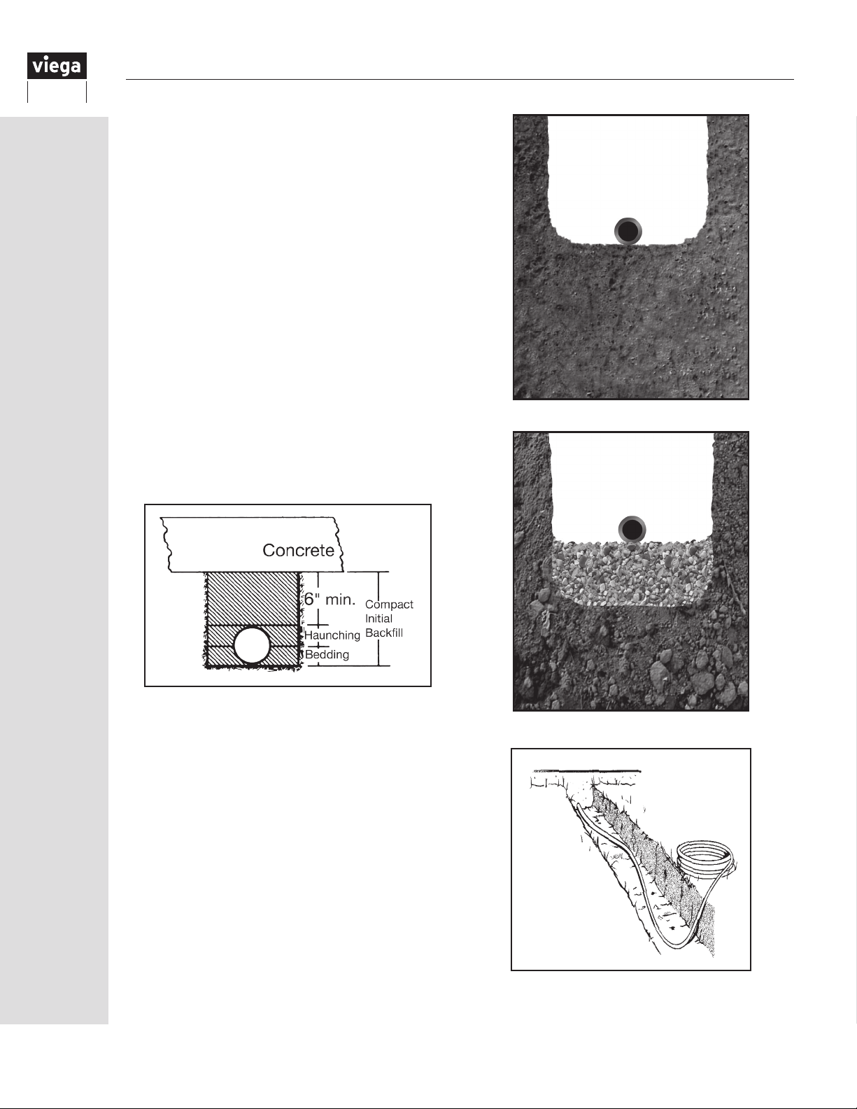
11 Water Service Installation
11.1 Below grade and service line
ViegaPEX Ultra and FostaPEX tubing may both be
used underground and for water service piping. When
running lines underground, it is important to provide a
stable, continuous trench base to support the tubing.
Always allow sufcient slack when tubing is laid in
trenches. Snake the tubing slightly side-to-side to
provide for contraction due to temperature change.
Do not use blocking to support tubing. PEX tubing
can be damaged by contact with sharp objects.
Ensure that trench bottom and ll do not contain sharp
rocks or other items. In good soil conditions tubing
may be placed directly on trench bottom. In poor soil
conditions (rocky, loose, etc.) the trench should be
excavated at least six inches below the tubing level and
backlled with appropriate material to provide a stable
base (coarse sand, pea gravel or similar).
Backll material must be free of large rocks, glass or
other sharp objects. Provide sufcient coverage over
tubing so that expected trafc loads will not deform
tubing (consult local codes). Compact this material to at
least 6" above the tube.
Trench in good soil
Do not install ViegaPEX Ultra tubing where soil is or
may become contaminated with solvents, fuels or
similar chemicals. Do not install tubing above or below
septic tanks, leach elds, pits or cesspools.
Always follow local codes when installing ViegaPEX
Ultra tubing. Consult standards such as ASTM D2774:
Standard Recommended Practice for Underground
Installation of Thermoplastic Pressure Piping for further
information.
24
Trench in poor soil
Allow sufficient slack when tubing is laid
in trench
IM-PF 724596 0416
Page 25
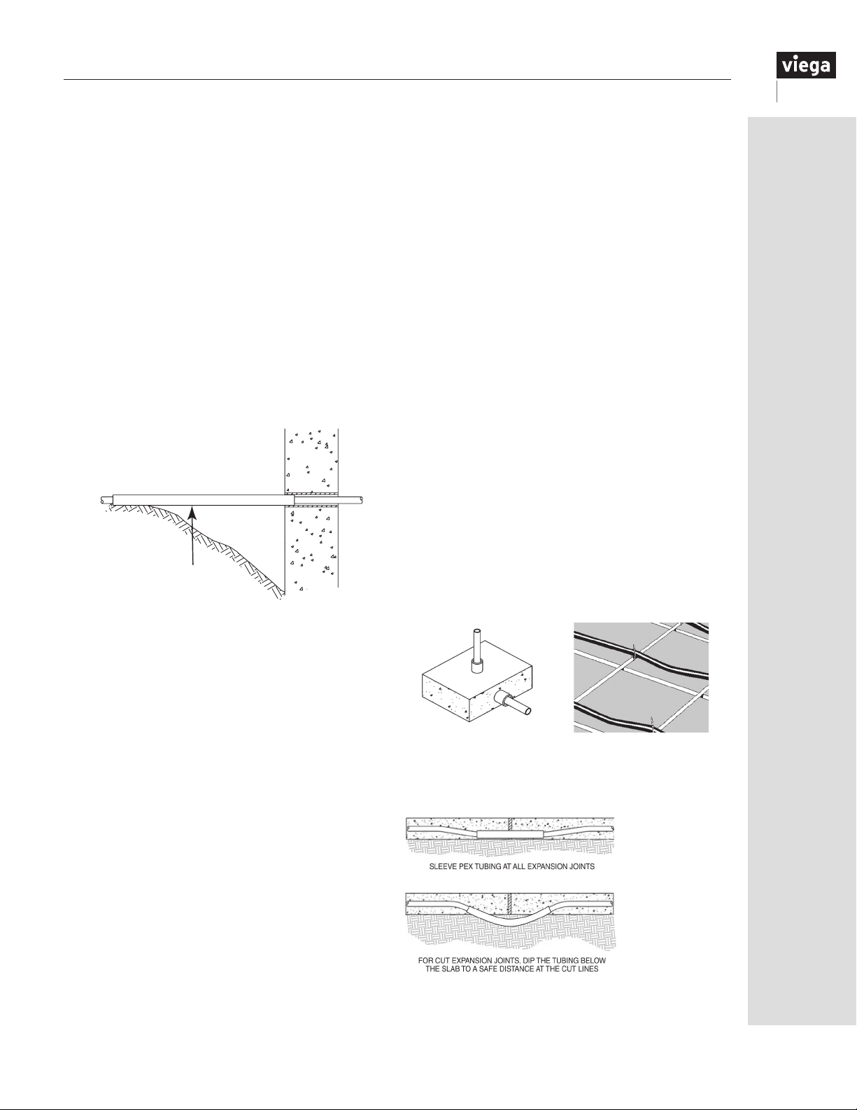
11.2 Foundation penetration
Where service lines penetrate foundation or basement
walls, to prevent shearing or pinching off of the tube
when backll below the tubing settles, plastic tubing
must be properly sleeved.
If there is an area of over-excavation through which the
tubing must pass, it shall be sleeved with a larger rigid
pipe (Schedule 40 PVC or equivalent) to undisturbed
earth. The foundation end of the rigid pipe must also be
supported by the foundation wall.
Slight over-excavations (12" or less) do not require
rigid sleeving when the area below the tubing is backlled and well compacted to the level of penetration.
Always sleeve plastic tubing where it passes through
concrete. Do not use oil-based caulks or sealants in
contact with tubing.
Sleeve to undisturbed
earth with rigid pipe.
11.4 Concrete
ViegaPEX Ultra and FostaPEX tubing may berun within
concrete slabs. All penetration points must be sleeved
to prevent tubing damage (entry/exit points, expansion
joints, etc.). Penetrations in walls, etc., may be sealed
with silicone caulk. Do not use oil-based caulk. Every
effort should be made to use only continuous lengths
of tubing within a slab. If the use of ttings buried in
concrete is necessary for repairs, all such ttings must
be wrapped with insulation, noncorrosive tape (no
adhesives) or sleeved to prevent corrosion. The wrap
shall be a self-fusing, formaldehyde-free, fully cured
silicone tape with a minimum of 0.020" thickness.
The wrap is available from Viega (part number
15320). Contact a Viega representative for additional
information on approved wrapping materials.
When running tubing within a concrete slab, the tubing
must be fastened to the reinforcing mesh or rebar
every two to three feet to prevent it from oating up
while concrete is curing.
11.5 Installing under the slab
When installing ViegaPEX Ultra or FostaPEX tubing
in the ground under the slab, the tubing should be
snaked from side to side in the prepared trench. The
trench bottom should be smooth and free of rocks and
debris. Lay the tubing directly on the trench bottom.
Tubing must be continuously supported by the trench
bottom. Use only continuous lengths of tubing in or
under slab. Any connections shall be outside the slab
or in an access box.
11.3 Direct burial of Viega PEX fittings
Installing PEX ttings in direct contact with ground
soil (direct burial) may require protective measures.
Refer to the below direct burial requirements for
each tting type.
Viega PEX Press ttings (Zero Lead bronze and
polymer) do not require any protective wrap for
direct burial installations.
Viega PEX Crimp ttings (Eco Brass and Polymer)
and their crimp rings shall be securely wrapped
with tape meeting the following criteria for direct
burial installations.
• Self-fusing
• Formaldehyde-free
• Fully cured silicone tape
• Minimum of 0.020" thickness
The wrap is available from Viega (part number
15320).
Elbow sleeves
protect tubing at concrete
slab penetrations
Tubing must be fastened
to the reinforcing mesh
on rebar
PEX tubing must
be sleeved at
all expansion
joints and every
point where it
enters, exits
or penetrates
the slab. For
expansion joints
that are to be
cut, the tubing
must be dipped
below the slab to
prevent damage.
IM-PF 724596 0416
25
Page 26
11.6 Protecting ViegaPEX Ultra tubing
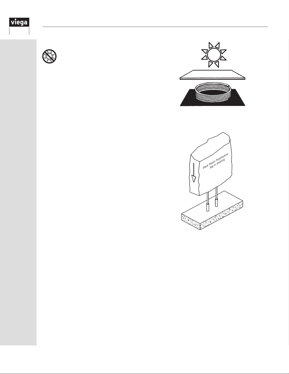
Protect tubing and ttings from UV
exposure.
Due to the nature of slab-on-grade installation, tubing
and ttings may be exposed to UV light for unspecied
periods of time.
To prevent damage from UV exposure, all ViegaPEX
Ultra tubing and polymer ttings shall be protected
with an opaque covering (black plastic polyethylene
bag or sheeting) immediately after they have been
installed.
PEX tubing shall be stored under cover, shielded
from direct and indirect sunlight when the material is
stored for any length of time. Short exposure times
of ViegaPEX Ultra, FostaPEX and polymer ttings
not exceeding the total accumulated recommended
exposure time are permissible.
Informing the other trades of the presence of the lines
may help prevent damage.
When the tubing penetrates at an angle in relation
to the hole, it may be subject to a sharp edge that
can damage the pipe. Acceptable sleeving materials
include exible plastic tubing, foam pipe insulation or
an approved plastic insulator.
It is not necessary to sleeve PEX when penetrating
wooden framing members or non-metallic nished or
unnished walls. However, if there is a doubt, sleeve
the pipe or install an insulator.
PEX tubing should always be shielded
from direct and indirect sunlight
26
Protect all exposed tubing with an opaque covering
IM-PF 724596 0416
Page 27

12 Installing the ManaBloc
Internal Divider Plate
Hot Port(s)
Cold Port(s)
Cold Water
Supply
Inlet or Outlet
Plastic Mounting
Bracket
12.1 Overview and carton contents
Additional package contents include:
• Valve T-Handle
• Instruction Sheet/Drill Guide
• Port Labels
12.2 Location
Before installing the ManaBloc, review the following
instructions.
NOTE: The ManaBloc is much like an electrical
breaker box. When a xture needs repair, the line
to that xture may be shut off at the ManaBloc,
eliminating the need to shut down the water supply
for the entire house. This feature requires that the
ManaBloc be accessible after installation.
COLD WEATHER CAUTION! The thermoplastic
components of the ManaBloc, like all
thermoplastics, have decreased resistance to impact
under freezing conditions and can be damaged.
Care must be exercised when installation occurs in
freezing conditions.
BEFORE INSTALLING THE MANABLOC, MAKE SURE
THE LOCATION REQUIREMENTS HAVE BEEN MET.
Take extra caution when handling the ManaBloc
in temperatures that are below freezing. Tubing
penetrations may require sleeving or the installation
of an insulator.
Valve Key
Port Valve
Cold Port(s)
Typical 24-Port ManaBloc
1. UNDER NO CIRCUMSTANCES shall the ManaBloc
be located in a permanently covered area (behind
sheetrock, plywood, paneling) or where freezing
temperatures may occur. Do not install in direct
sunlight. THE MANABLOC MUST BE ACCESSIBLE
and there shall be sufcient clear area in front of the
ManaBloc to provide access.
2. When local code allows, mount the ManaBloc
unit in a re-rated wall, provided an access door
meeting the same rating requirements as the wall is
installed over the access opening.
When installing the ManaBloc in a location
3.
other than between studs, provisions must be
made to support the tubing runs as they exit the
ManaBloc. (See “15.3 Bending ViegaPEX Ultra
tubing” on Page 43).
4. Any installed cover panel shall allow access to
the ManaBloc and its mounting screws, the port
valves, distribution line connections and supply
line connections.
5. To maximize potential water and energy savings,
the ManaBloc should be mounted as close as
is practical to the hot water source, taking the
following into consideration:
a. When the ManaBloc is mounted above the
water heater, there shall be a minimum of 36"
of connecting tubing between the water heater
and the ManaBloc to reduce the chance of
heat stacking.
Hot Water
Supply Inlet
Cold Water
Supply Inlet
or Outlet
IM-PF 724596 0416
27
Page 28
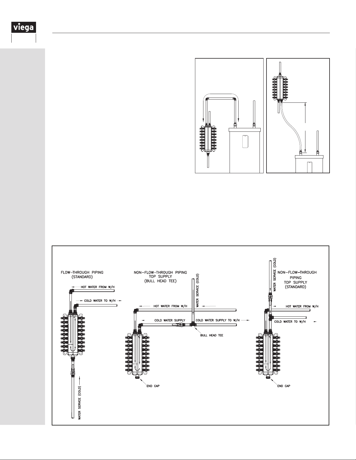
b. When the ManaBloc is mounted beside the
water heater and is connected with tubing
incorporating a horizontal ow, there shall be at
least 18" of developed tube length. Mounting
the ManaBloc within eight feet of developed
tube length of the water heater will minimize
delivery time of hot water to individual xtures.
The ManaBloc may be mounted closer than
12" to the hot water source (tank) if it does not
exceed the minimum allowable vertical and
horizontal spacing outlined in this section.
c. Install the unit in an area that is centrally located
to the most dense concentration of served
xtures. Some applications will require that the
ManaBloc be mounted farther than eight feet
from the hot water source. See design factors
for installing a parallel system, “3.1 Home
run systems” on Page 8, for suggestions
on reducing hot water delivery times in these
instances.
6. DO NOT install the ManaBloc within a continuously
recirculating hot water plumbing loop. The
ManaBloc, however, may be supplied from a
recirculating hot water loop. Refer to “Section 16.10
Domestic hot water circulating systems” on Page
54 for recommended piping options.
ManaBloc Locations
18” TO 8’ TOTAL
DEVELOPED TUBE LENGTH
36” MIN
7. Position the ManaBloc so that it can be securely
fastened through the holes provided in the mounting
brackets. The mounting surface should be as at as
possible so as not to induce any twisting or bending
forces on the unit. The mounting straps (part
number 45716) simplify mounting between studs on
16" centers.
ManaBloc Supply Piping Options
28
IM-PF 724596 0416
Page 29
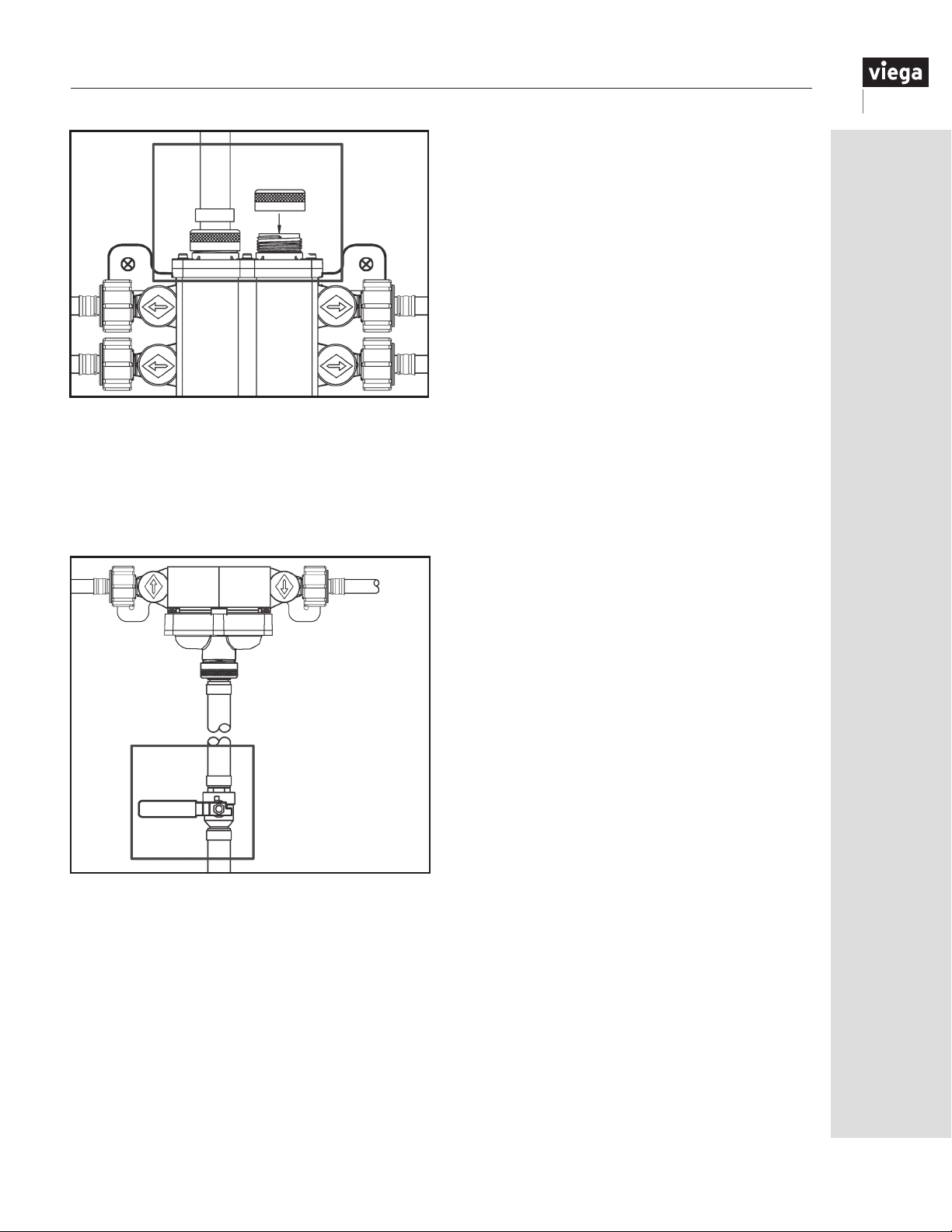
If a main inlet/outlet will not be used, it must be
capped. (Use part number 53601.)
The main service line to the ManaBloc may include
a main shutoff valve, as required by local code.
Although a shutoff valve for the main service line at the
ManaBloc itself is not required, it can be a benecial
option for a homeowner and is recommended.
Optional
ManaBloc
shutoff
Local code may also require the installation of a check
valve, Pressure Reducing Valve (PRV), back ow
preventer, etc. To prevent debris and other particles
from entering the system, a strainer may be installed
in the service line.
12.3 Draining the ManaBloc unit
If the ManaBloc system has been lled with water and
there exists the possibility that the ambient temperature
will drop close to or below 32°F (0°C), the ManaBloc
unit MUST be drained to prevent irreparable damage.
The process of draining involves loosening and removal
of one or more supply line connections and two
distribution lines from the ManaBloc.
NOTE: Depending on the installation, some supply
connections may be capped. If that is the case, remove
the cap(s) as instructed below.
1.
Turn off all water supply(s) feeding the
ManaBloc. Open both sides of all fixtures
served by the manifold and leave the fixtures
open during draining. For each port of the
ManaBloc where there is a distribution line
connected, make sure the port valve is in the
open position.
2.
Loosen and remove the bottom supply
connection(s) (or cap(s)) and the lowest pair of hot
and cold distribution lines.
3.
As the connections are removed, most of the
water contained in the ManaBloc main bores and
some of the water in the distribution lines should
purge from the system.
4.
Allow to drain until no water purges.
5.
Reattach the supply line(s) or cap(s) and the
distribution lines. Tighten the supply connections
according to the instructions in Section 14.5.
When reconnecting the distribution lines, DO
NOT overtighten the connections. These only
need to be hand-tight.
NOTE: The procedure described above will leave
a small amount of water in the ManaBloc unit and,
depending on the installation, may leave some or most
of the water in the distribution lines. This remaining
water should not cause damage to the manifold unit
or to the PEX distribution lines in the event of a freeze.
However, for complete assurance that freeze damage
will not occur, perform the following additional steps.
IM-PF 724596 0416
29
Page 30
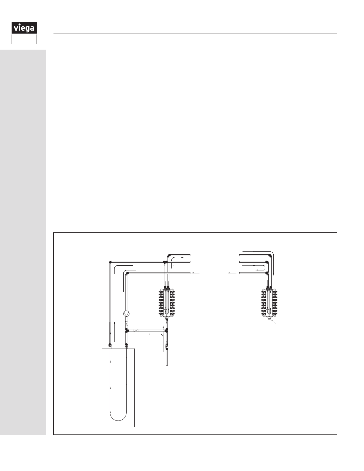
12.4 Draining the ManaBloc system
1.
Loosen and remove all of the supply line
connections (or caps) and all of the distribution
lines from the ManaBloc.
2. Remove the four attachment screws and
withdraw the ManaBloc unit from its mounting.
Note: Grasp the unit firmly before removing the
last attachment screw to prevent the unit from
falling and being damaged.
3. Completely drain the ManaBloc unit by
inverting the unit several times until there
is no water coming from any of the supply
connections or ports.
4. To purge the PEX distribution lines, first make
sure that both sides of all of the fixtures are in
the open position. Using low-pressure air from
a tank or compressor, force the water from the
lines by connecting the air pressure source to
each line one at a time and blow air through the
lines until no water flows from the fixtures.
5. Reattach the ManaBloc and reconnect the
supply and distribution line connections.
NOTE: When reconnecting the distribution lines,
DO NOT overtighten the connections. Compression
connections should require only about ⅛ turn past
hand-tight when reinstalling connections that were
previously tightened to the specications outlined
in this installation guide. PEX Press and PEX Crimp
connections must be only hand-tightened.
12.5 Multiple ManaBloc installations
If a home requires multiple ManaBlocs to service
the number of xtures in the home, these guidelines
should be followed if the ManaBlocs are closely
located to each other.
• Consider dividing high-demand xtures between
the units
• Consider a reasonable division, i.e. upstairs/
downstairs, east/west or front/back
Locating a remote ManaBloc
A remote ManaBloc is sometimes recommended
to achieve maximum efciency from your
ManaBloc system. It is advantageous when the
line lengths are excessive from one centralized
ManaBloc unit. When the home requires more than
one unit due to the number of xtures or size of
the home, consider locating a remote unit near an
outlying group of xtures.
Domestic Hot Water Circulating Loop Supplying Two ManaBlocs
Cold Water Supply
Hot Water Supply
Hot Water Supply
Hot
Hot Return
Circ
Pump
Check Valves
Cold
Cold Supply
Hot Return
End Cap
30
Water Heater
IM-PF 724596 0416
Page 31
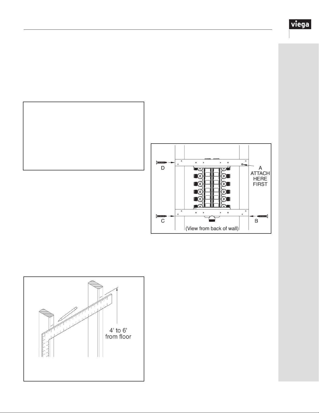
13 Mounting the ManaBloc
13.1
Mounting the ManaBloc between studs
Dimensions in these instructions are for 16" stud
centers and must be adjusted for other stud spacing.
Once the general location of the ManaBloc has been
determined (see “12.2 Location” on Page 27), the
ManaBloc may be mounted to a suitable surface
between a pair of adjacent studs. For 16" stud
spacing, the mounting straps (part number 45716) can
simplify installation.
Additional Tools and Materials
• Electric Drill
• #2 Phillips Head Screwdriver
• Pencil or Pen
• Permanent Marking Pen*
• Framing Square
• Tape Measure
• ¾" and 1¼" Wood Drill Bits
• ManaBloc Wrench* - for compression ManaBlocs only
• Wood or Drywall Screws - ½" or longer
• ½" or ¾" Plywood - when ush mounting ManaBloc
*Optional
1. Lay the ManaBloc, plastic brackets down, on
a suitable at surface that is large enough to
accommodate the full length of the ManaBloc.
Place a mounting strap under each plastic mounting
bracket (located at the top and bottom ends of the
ManaBloc). Attach the plastic mounting bracket at
one end of the ManaBloc to the two outer center
holes of a mounting strap using the provided selftapping pan-head screws. The screw heads must
be on the accessible side of the mounting strap.
Repeat at the other end of the ManaBloc. Tighten
screws securely.
2. Standing behind the stud wall, measure up from
the oor and make a mark on the back of one of the
studs to represent the top of the ManaBloc. (See
illustration.)
This mark should be between four feet and six
feet from the oor but may be at any height,
provided the height will allow all valves on the
ManaBloc to be accessible. With a framing square
or level, transfer and mark the noted height on
the other stud.
NOTE: A residence intended for disabled persons may
require that the ManaBloc be mounted lower in the
wall to provide access.
3. Standing behind the stud wall, hold the ManaBloc
facing away from you and align the top of the
UPPER mounting strap to the line on the stud that
you made in Step 2. Loosely attach this mounting
strap ush to the back outer edge of one stud using
a ¾" or longer drywall or other suitable wood screw
(A). (See illustration.)
4. Line up the LOWER mounting strap with the back
outer edge of the stud and attach it in the same
manner (B). Attach the remaining strap ends (C and
D) to the other stud, and tighten all screws.
Measure up from the oor while standing
behind the stud wall. Mark a location for the
top of the ManaBloc.
IM-PF 724596 0416
31
Page 32
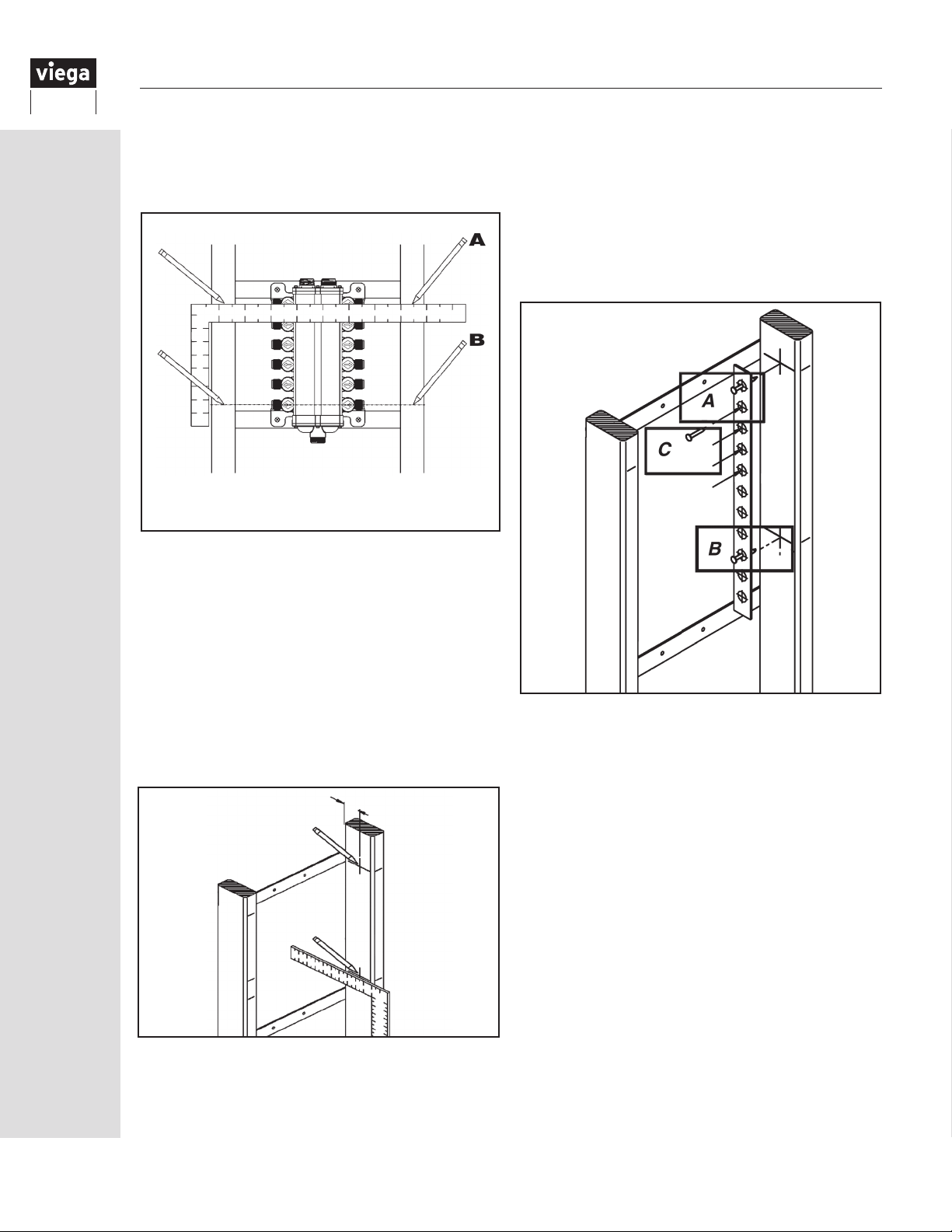
5. Standing in front of the wall, using a framing square
or straight edge, mark the center line position of
the top and bottom ports onto both studs. (See
illustration.)
Mark the centers of the top and bottom
ManaBloc ports (A, B)
6. Detach the ManaBloc from its mounting straps (or
1x4s) and remove it from the installation area to
prevent wood chips or other debris from falling into
the unit.
7. Transfer the port location marks made in Step 5
to the insides of the stud cavity using a square
and pencil.
8. Measure 1⅝" from the mounting surface. Draw a
vertical line on the studs that passes through each
of the horizontal port center lines marked in Step 7.
(See illustration below.) Be sure to mark the inside
of both studs.
1⅝"
9. Push a small nail through the printed center line at
one end of the Drill Guide (A). Push the nail into the
cross formed where the top port mark intersects
with the 1⅝" mark. Tap the nail into the stud to
hold the Drill Guide in place.
10. Push a small nail through the printed center line on
the lower end of the Drill Guide with the center line
of the port (B). Tap the nail into the stud to hold
the Drill Guide in place.
11. Using an awl, nail or other pointed tool (C), mark
the stud by tapping through the Drill Guide at each
printed center line between the two nails.
12. Carefully remove the Drill Guide and repeat the
marking procedure on the adjacent stud.
13. Drill ¾" holes through both studs at each
marked location. Be sure to hold the drill level
perpendicular to the stud to prevent drilling holes
at an angle. Remove any splinters or burrs made
during drilling.
14. Mark and drill any holes for main water supply
and hot water supply/return lines at this time. A
1¼" bit will provide adequate clearance for ¾" or
1" tubing. The tubing shall enter and/or exit the
ManaBloc in a straight line so as not to induce
bending stress on the ManaBloc. Necessary
elbows, couplings and tees are allowed in the main
water supply lines.
32
IM-PF 724596 0416
Page 33
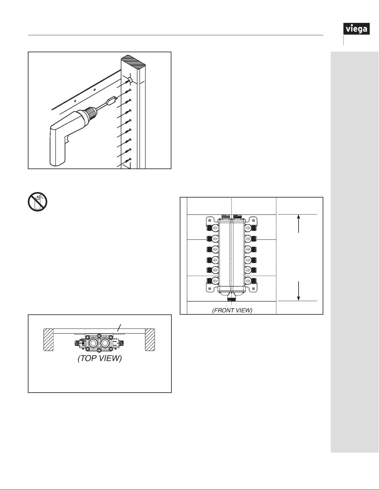
Drill ¾" holes for
distribution lines, 1¼"
holes for supply lines.
15. Reattach the ManaBloc to the mounting straps.
When the ManaBloc is installed prior to
wall finishing operations, the unit MUST be
protected from paint, texture compounds
and drywall dust.
NOTE: The wall in which the ManaBloc is mounted
must be accessible from both sides during installation
to use the mounting straps.
13.2 Mounting the ManaBloc between studs without use of mounting straps
If not using the mounting straps, this procedure applies:
2. The top of the ManaBloc should be between four
feet and six feet from the oor (but may be at any
height provided that it maintains accessibility to
all of the ports on the ManaBloc). Make a mark
near the back of the inside of one stud that would
represent the top of the ManaBloc. With a framing
square or level, mirror the mark on the inside back
of the other stud.
3. Attaching the ManaBloc between the studs:
a. Measure the total length of the ManaBloc.
b. Attach the rst (UPPER) 1x4 inside and ush to
the back of the studs (see TOP VIEW, below left)
at a height where the center of its width is
centered on the marks from Step 2.
c. Attach the remaining (LOWER) 1x4 inside and
ush to the back of the studs at a distance below
the upper 1x4 that is equal to the length of the
ManaBloc (Step 3a) when measured from the
top of the upper 1x4 to the bottom of the lower
1x4. (See FRONT VIEW illustration.)
Step C:
Distance
between top
and bottom
of 1x4s equal
to length of
ManaBloc
1. Cut two pieces of lumber (1x4 — or ¾" plywood —
approximately 3½" wide) to a length that provides a
snug t BETWEEN two studs.
1x4
1x4s attach at the back, inside the studs,
and the ManaBloc is centered between
the studs.
IM-PF 724596 0416
4. CENTER THE MANABLOC IN THE STUD CAVITY:
Attach the ManaBloc to the 1x4s with four ½" - ¾"
drywall screws. DO NOT OVERTIGHTEN.
5. Continue to Section 13.1, Step 5, to nish
installation.
33
Page 34
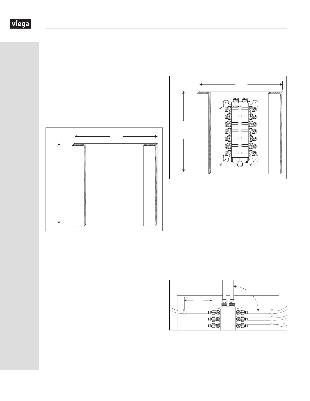
13.3
Mounting the ManaBloc - surface mount
1. A suitable base for the ManaBloc can be
constructed from a section of ½" or thicker
plywood that is a minimum 22½" wide and slightly
longer than the overall length of the ManaBloc.
2. Securely attach a length of 2x4, or other suitable
framing material with a thickness of 1½" and about
3½" wide on the left and right sides of the mounting
base running the full length of the ManaBloc. (See
illustration below.) The 2x4s will be used to secure the
distribution lines at the correct height as they exit the
ManaBloc. (Support clamps not to exceed 6" spacing
from end of ports.)
22½"
Longer
than
ManaBloc
2x42x4
3. Attach the mounting base to the structure in a
suitable location. (See “12.2 Location” on Page
27.) The base should be mounted so the top of
the ManaBloc is between four feet and six feet from
the oor but may be at any height provided that the
height maintains accessibility to all the ports on the
ManaBloc.
4. The mounting base must be rmly attached to a
structure solid enough to support, at a minimum,
the weight of the ManaBloc lled with water. The
base should be square and level.
5. Center the ManaBloc on the base both vertically and
horizontally, as shown here. Attach the ManaBloc to
the mounting base with four ½" or longer drywall or
wood screws through the holes in the plastic brackets
on the ManaBloc. DO NOT OVERTIGHTEN.
22½"
®
MANABLOC
Longer
than
ManaBloc
2x42x4
6. As the distribution lines are connected to the
ManaBloc (see “14.3 Connecting distribution lines
to the ManaBloc” on Page 38), ensure that the
tubing exits the unit at a 90° angle to the center
line of the ManaBloc so as not to induce bending
stress on the ManaBloc.
7. When attaching the distribution line tubing to the
2x4 supports, be sure to use appropriately sized
Viega tubing clamps. (For example, use part
number 52000 for ⅜" tubing and part number
52020 for ½" tubing.)
Use one clamp per tube to ensure that the tubing
is held securely. Position clamps NO FARTHER
than 6" from the end of the port. DO NOT pull
tubing tight.
90°
4"- 6"
34
IM-PF 724596 0416
Page 35
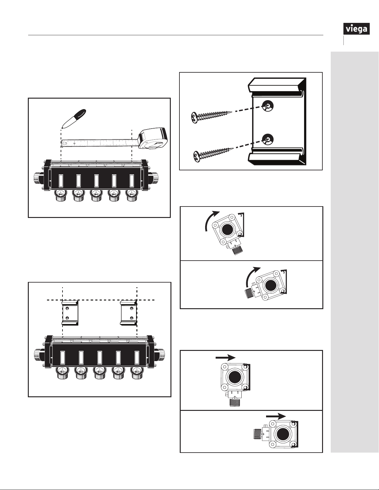
13.4 Mounting the MiniBloc
1.
For proper bracket spacing, measure distance
between the center ribs of the rst and last
MiniBloc modules. Mark this distance on the
selected mounted surface.
6
5
2 3
1
4
3. Use two wood screws per bracket, 1" or longer,
to prevent misalignment.
3
1
4. Position bottom metal tie-rod into the bottom clip
of the mounting brackets then roll manifold
toward top clip. The MiniBloc may be mounted
either vertically or horizontally.
4
2. Align the outside edge of each bracket within
each end mark. Mounting brackets shall be
mounted level and parallel to each other before
afxing the MiniBloc manifold. NOTE: Use both
mounting brackets provided with each MiniBloc
manifold. Ensure the mounting surface is suitable
to support the weight of the manifold and
attached tubing when lled with water.
2
Vertical
Mount
Horizontal
Mount
5. Complete mounting by rmly pushing the
MiniBloc toward the top clip of the mounting
brackets, which should spread and snap over
top metal tie-rod.
5
Vertical
Mount
IM-PF 724596 0416
Horizontal
Mount
35
Page 36
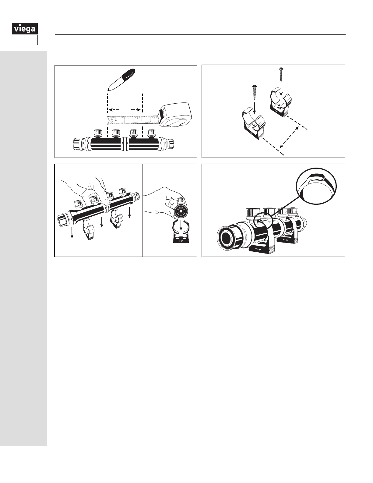
13.5 Mounting Viega PEX Press and PEX Crimp Polymer manifolds
A
6
5
4
2 3
1
B
1
3
2
4
A
Viega recommends using a minimum of two mounting brackets on manifolds with three ports and larger.
1. Measure the distance (A) between the rst and last set of manifold ports (as shown). Using a straight
edge, mark dimension (A) on mounting surface. Ensure the mounting surface is level and suitable to
support the weight of the manifold lled with water.
2. Align the 1¼" lock clips* (B) with the marks transferred on the mounting surface from Step 1 and
attach them using a 1" or longer screw appropriate for the mounting surface.
3. With the lock clips in the open position, insert the manifold body into the clips, centering them between
the end ports.
4. Push evenly on both ends of the manifold until lock clips snap manifold body rmly into place.
NOTE: Lock the clips into their second locking position to adequately secure the manifold.
* Lock clips sold separately (part number 58075).
36
IM-PF 724596 0416
Page 37
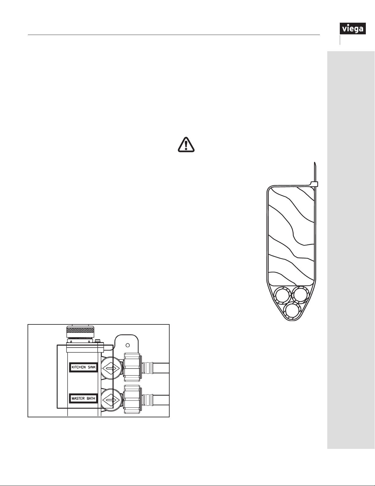
14 Installing Manifold Distribution Lines
14.1 Installing manifold distribution lines
Run distribution lines continuously in the most direct
route from the ManaBloc to the xtures.
A distribution line may contain a coupling or other
tting for purposes such as repairing a damaged section
of tubing, handling a change of direction that cannot
be made within the minimum bend radius guidelines,
accommodating a xture location change that requires a
longer line or supplying a low-demand accessory (i.e., ice
maker). However, several pieces of shorter tubing should
not be connected with ttings for the purpose of using
up leftover lengths of tubing.
NOTE: It is the responsibility of the installer to
ensure that further construction, nishing and other
mechanical system installations do not compromise
the ManaBloc plumbing system as installed according
to these instructions.
1. Tubing coils are usually placed at the ManaBloc
location and tubing is pulled to the xture through
stud cavities, holes drilled overhead in oor joists,
etc. Several tubes may be pulled at one time. Viega’s
color-coded ViegaPEX Ultra tubing helps prevent
cross-connections.
2. Do not pull tubing tightly. Some slack (7" per 50
feet) is necessary to accommodate expansion and
contraction. Leave enough excess tubing at the
beginning and end of runs to make connections
without putting strain on the tubing.
3. Exercise care when pulling PEX tubing to prevent
cutting or abrading. Take care to prevent kinking of
the coiled tubing. If kinking or cutting occurs, cut
out the damaged section and install a coupling.
4. For the best results, connect the distribution
lines to xtures and the ManaBloc immediately
upon installation. Label the end-use xture on the
ManaBloc cover plate next to the port.
5. Since plumbing xtures are generally located in
groups, and there may be several ViegaPEX Ultra
distribution lines running to approximately the same
location, it is easiest to run these distribution lines
bundled together.
For a neat appearance, tie bundles with nylon ties
(part number 43714 or 43701 or plastic strapping at
regular intervals).
NOTE: Bundles shall be sufficiently tied for tubing
support but shall NOT restrict tubing expansion
and contraction caused by temperature variations.
CAUTION: DO NOT USE DUCT TAPE
FOR BUNDLING. Duct tape will not permit
tubing movement.
6. Bundles can be supported with hangers
designed for larger tubing sizes.
7. The nylon ties can be used
to support PEX lines directly
from wooden framing
members.
Any plastic cable ties capable
of supporting the weight of
the tube or bundle when lled
with water can be used.
8. Holes drilled through studs,
joists, plates, headers, etc.,
must be large enough to
accommodate tubing bundles
without binding to allow free
movement. Several smaller
holes (accommodating a few
lines each) may be preferable
to drilling a bundle-size hole.
In no case should the hole size
exceed building code guidelines,
as this could weaken the structural
support members.
For more detailed instructions, refer to Section 15 of
this guide.
Self-adhesive labels are supplied with the ManaBloc.
Mark tubes pulled as a bundle or those not connected
immediately at both ends with a permanent marker to
designate the fixture supplied.
IM-PF 724596 0416
37
Page 38
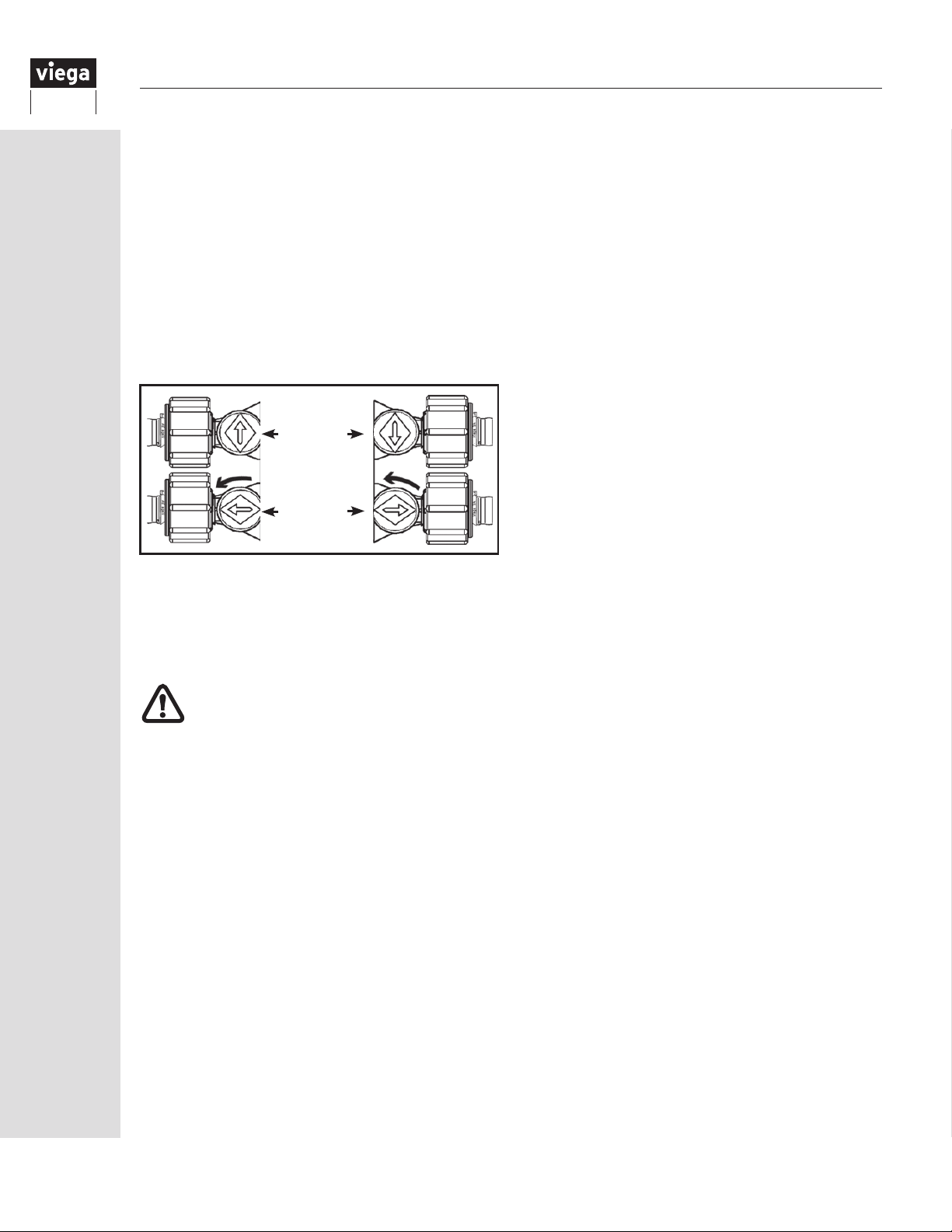
14.2 Valve operation
A ManaBloc system, which has valves on all of the
outlet ports, does not require stop valves at the
xtures. However, the Authority Having Jurisdiction
(AHJ) may require stop valves at some xtures.
Use the included red key handle to turn each
port ON or OFF. Valves are marked with arrows
indicating their ON/OFF positions:
Left Port – Arrow Up for OFF
Arrow Left for ON
Right Port – Arrow Down for OFF
Arrow Right for ON
Valve
OFF
Valve
ON
(¼ Turn)
Note: These valves are eld-repairable. Contact
Viega Customer Service for more information on
this procedure.
14.3 Connecting distribution lines to the ManaBloc
THE WATER SUPPLY TO THE
MANABLOC AND THE PORT VALVES
SHALL BE TURNED OFF BEFORE
ATTEMPTING INSTALLATION OF PEX
CONNECTIONS.
PEX Press, PEX Crimp and Compression
connection models are available and included with
each ManaBloc model. Supply connections are not
included and must be ordered separately. If there
are unused ports, Viega recommends capping
them to protect from the home owner opening the
wrong valve. Use part number 36205 (½" ports) or
36204 (⅜" ports).
38
IM-PF 724596 0416
Page 39
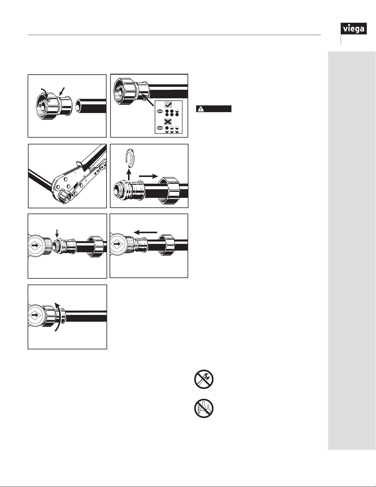
14.3.1 Port connections
CAUTION
For PEX Press connections:
A
B
1 2
3
A
5
C
7
The water supply to the ManaBloc and
the port valves shall be turned off before
attempting installation of press adapters.
Use only sealing elements
supplied with the adapters.
1. Ensure sealing element (A) is in place and
the tool locator ring (B) is present in its
B
factory-installed position.
2. Square off tubing to proper length and
C
insert the tting fully into the end of the
tubing as shown. Full insertion means
tubing must be completely visible in
at least two viewing holes and may be
4
partially visible in one.
3. Place the PEX Press tool jaw over the
attached press sleeve, resting it against
the tool locator ring. Press the sleeve
with an appropriately sized press jaw.
DO NOT PRESS TWICE. Refer to current
Viega PEX Water Systems Manual for
additional pressing information.
4. Remove tool locator ring (B) and slide
6
swivel nut (C) over tubing as shown.
5. Ensure sealing element (A) is in place and
clean of any dirt or debris. Wet sealing
element with tap water.
6. Insert the tting into the desired port until
the tting ange sets ush with the end of
the port.
7. Thread the swivel nut (C) onto the ManaBloc
port. Hand-tighten only. Open the port
valve(s) before turning on the main water
supply.
IM-PF 724596 0416
Hand-tighten only!
UNDER NO CIRCUMSTANCES
shall any form of thread sealant
(Teon® paste, pipe dope, etc.) be
used on distribution line connections.
The carriers present in these compounds can
crack the plastic port connections, resulting
in leaks and water damage.
39
Page 40
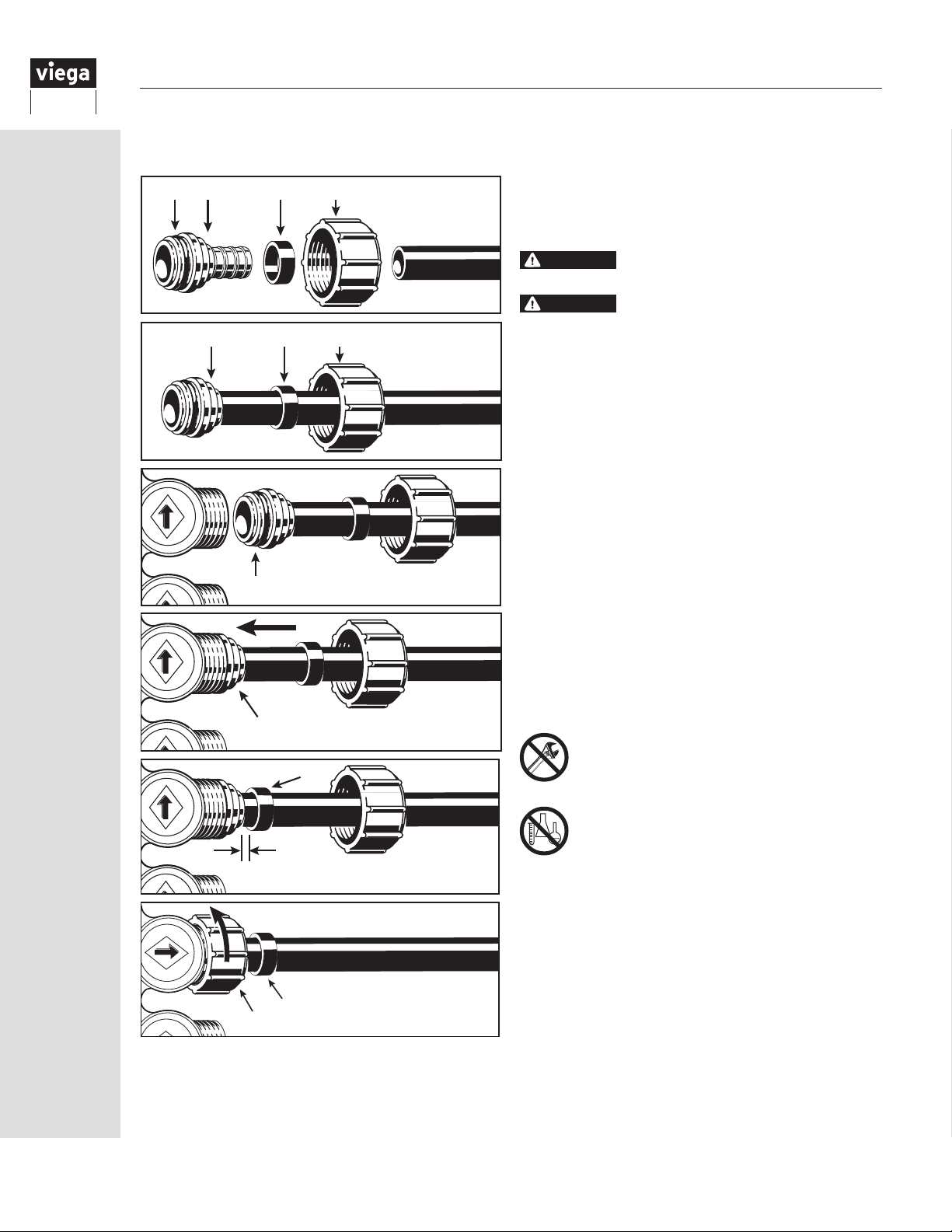
For PEX Crimp connections:
B
A
C
⅛" to ¼"
AB CD
CAUTION
CAUTION
The water supply to the ManaBloc and the port
1
valves shall be turned off before attempting
installation of crimp adapters.
Use only sealing elements
supplied with the adapters.
Not for use with FostaPEX
®
BCD
2
1. Ensure sealing element (A) is in place.
2. Slide the supplied swivel nut (D) and a crimp ring
(C) onto the tubing and insert the barbed end of
the fitting (B) fully into the end of the tubing as
shown.
3. Ensuring sealing element (A) is in place and
clean of any dirt or debris, wet sealing element
3
4
5
with tap water.
4. Insert tting (B) into desired port until the tting
ange sets ush with the end of the port.
5. Slide the crimp ring (C) to within ⅛" to ¼"
from the end of tube. Crimp the ring with an
appropriately sized full-circle crimp tool. DO
NOT CRIMP TWICE. See “6.5 Making a Viega
PEX Crimp connection” on Page 16.
6. Slide the swivel nut (D) over the crimped ring
(C) and thread the nut onto the ManaBloc port.
HAND-TIGHTEN ONLY. Open the port valve(s)
before turning on the main water supply.
Hand-tighten only!
40
UNDER NO CIRCUMSTANCES
shall any form of thread sealant (Teon®
paste, pipe dope, etc.) be used on
distribution line connections. The carriers
present in these compounds can crack the
plastic port connections, resulting in leaks
6
C
D
and water damage.
IM-PF 724596 0416
Page 41
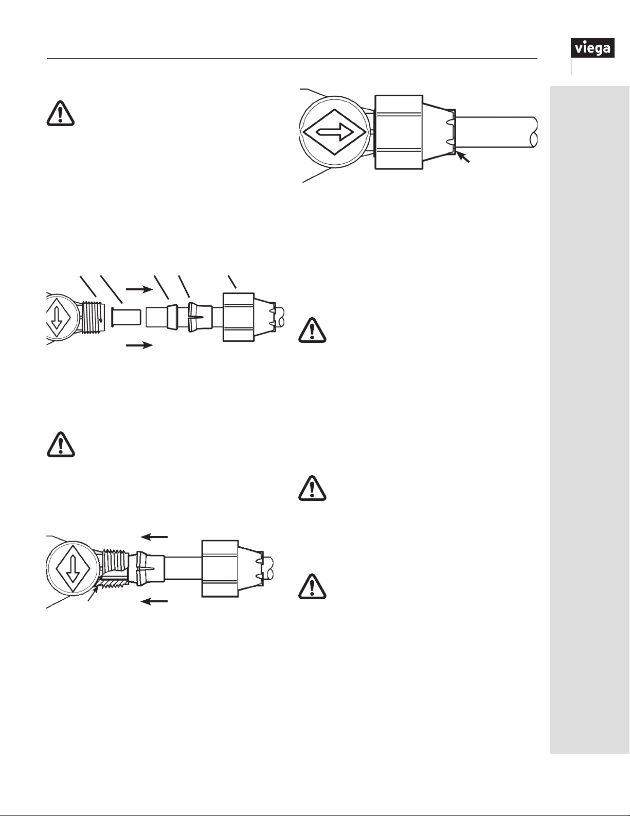
For compression connections:
NOT FOR USE WITH FOSTAPEX
NOTE: The red ManaBloc valves designate hot
ports and the blue valves designate cold ports.
Make sure the distribution lines are connected to the
correct ports (hot or cold). The use of color-coded
ViegaPEX Ultra tubing reduces the possibility of cross
connections.
1. For each distribution line, slide the Lock-In
compression nut (A), Lock-In insert (B) and the
plastic ferrule (C) onto the tubing in that order. (See
illustration below.)
E D C B A
The long taper of a ⅜" ferrule (C) must be TOWARD
THE END OF THE TUBE; a ½" ferrule is symmetrical
and may be installed facing either direction. Insert the
stainless steel stiffener (D) COMPLETELY into the
end of the tubing.
WARNING: DO NOT attempt to install the
Lock-In insert backward as it may break.
ALWAYS insert the long portion of the insert
sleeve over the tube rst.
DO NOT attempt to use or reuse inserts that are
defective, cracked, broken or otherwise damaged, as
connection failure will result.
LUG
3. While holding the tube securely to prevent turning,
nish tightening the nut with the ManaBloc Wrench
(part number 50631) until the white Lock-In insert
appears between the lugs and becomes ush with
the ends of the lugs, plus ¼- to ½-turn.
Complete the connection as soon as each distribution
line is connected to the ManaBloc.
be turned counter clockwise ¼-turn to the open
position after completing each connection, as
shown above.
WARNING: DO NOT use slip-joint pliers to
tighten the Lock-In nuts. Use the ManaBloc
wrench (part number 50631) to tighten the
compression connections.
4. After all connections are complete, recheck that all
of the Lock-In inserts are visible between the lugs
and are ush or protruding slightly beyond the lugs.
5. As the distribution lines are connected to the
ManaBloc, they should immediately be labeled on
the cover plate as to which xture that line supplies.
Fixture labels are included with each ManaBloc. Afx
the appropriate label to the cover plate next to the port.
COMPRESSION CONNECTION CAUTION
This plumbing system relies upon the
proper tightening of distribution line
compression connections.
Failure to properly complete ALL connections may
result in system failure. Incomplete or improper
connections can hold pressure during a system test
but may fail at a later date, resulting in water damage.
Each valve should
E
2. Push the tubing into the port socket (E) until it
bottoms out.
Holding the tube so that it does not back out of
the port socket, slide the white Lock-In insert
and ferrule snugly against the chamber inside
the port socket.
While holding the tube against the bottom of the
socket, thread the Lock-In compression nut onto the
port and tighten hand-tight.
IM-PF 724596 0416
DO NOT OVERTIGHTEN compression ttings.
Overtightening of the Lock-In compression nuts may
cause damage to the tubing, nut, valve or tting
body. DO NOT tighten Lock-In nuts beyond the
recommendation of these instructions (Step 3).
41
Page 42
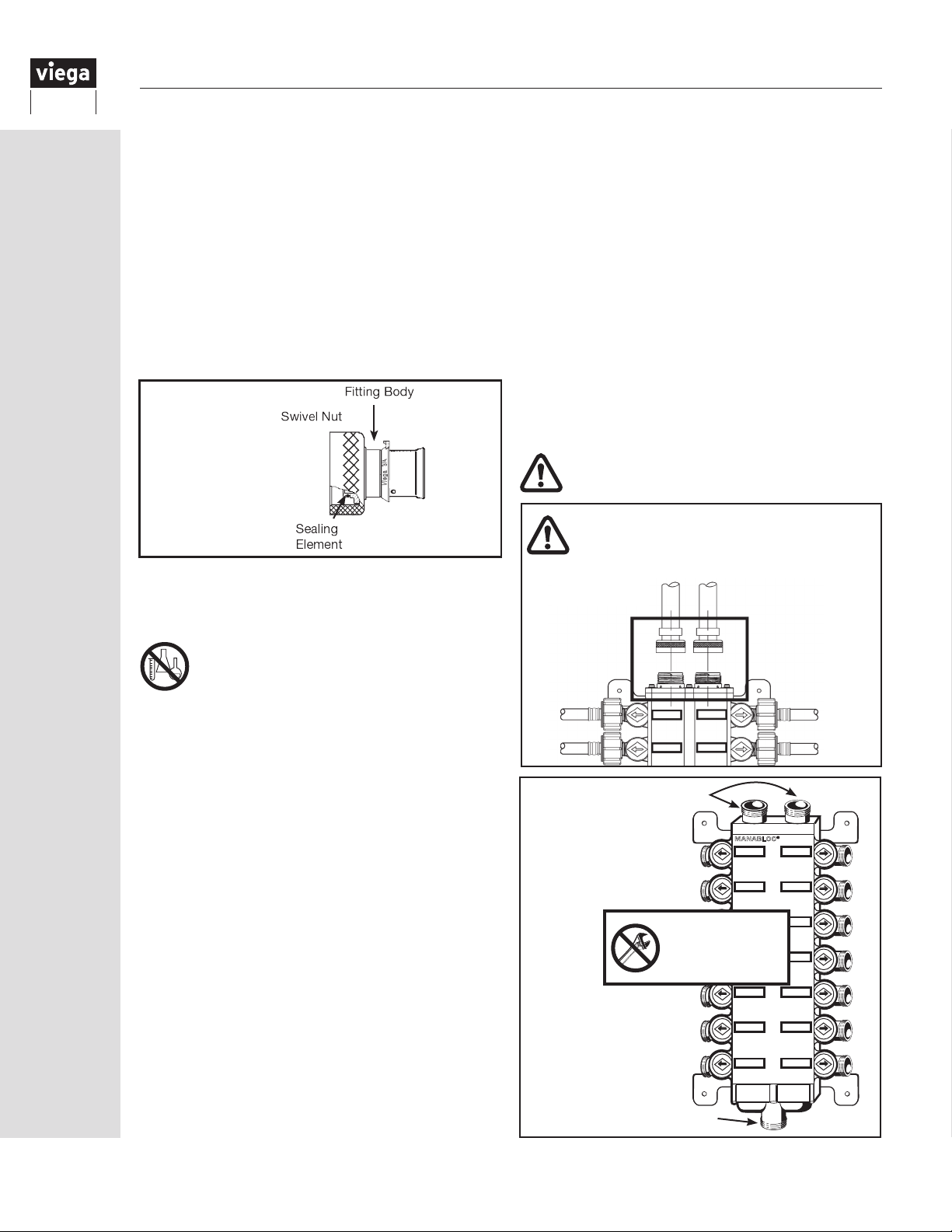
14.4
Connecting distribution lines to fixtures
There are a variety of male and female adapters,
sweat adapters, turn out supports and stub out
adapters to assist in terminating at the xture. Refer
to Section 17.1 though 17.4 of this guide or the
Viega
product catalog.
14.5 Water supply connections
The main water supply shall be turned off before
making water supply connections.
The ManaBloc water supply connection uses a special
1" swivel ManaBloc transition tting that seals with a
sealing element.
ManaBloc
Supply Adapter
(PEX Press shown)
This connection is used on the cold water supply and
the hot water supply/return lines. This connection to
the ManaBloc does not require any form of thread
sealant and none shall be used.
These compounds can attack the plastic materials
from which the ManaBloc is made and cause
crazing, cracking and failure of the ManaBloc,
resulting in leaks and water damage.
4. Ensure that the hot/cold supply lines are connected
to the correct supply inlet/outlet on the ManaBloc.
Red valves designate hot ports; blue valves
designate cold ports.
5. Supply lines shall enter and/or exit the ManaBloc
in a straight line. If bending of the supply lines
is required, the tubing must be anchored to a
framing member to isolate the bend stress from
the ManaBloc or use a directional tting.
6. After the supply tubing has been connected to the
transition tting, remove the plastic protective cap
from the ManaBloc inlet/outlet part and thread the
swivel nut onto the threaded male adapter hand-
tight only. DO NOT CROSS-THREAD.
DO NOT ELECTRICALLY GROUND
TO THIS SYSTEM.
Swivel ttings must be ALIGNED CORRECTLY
before being attached to the ManaBloc. The piping
material must not be allowed to put stress on the
ManaBloc, as leaking and damage may result.
DO NOT USE ANY FORM OF THREAD
SEALANT TO MAKE THIS CONNECTION.
NOTE: Water service connections to adapt to most
types of plumbing supply materials are available.
Consult the Viega Product Catalog for a complete
listing of available connections.
1. Connect water service adapters to water supply
piping before attaching the swivel tting to the
ManaBloc (instructions included with adapters).
Excessive force from threaded ttings or solvents
from solvent welding (PVC or CPVC) will cause
damage to the ManaBloc. Drill all holes in wood
members for water supply/return tubing BEFORE
mounting the ManaBloc.
2. When using male or female pipe thread transition
ttings, to connect to supply tubing, use only
Teon® tape to seal pipe threads. DO NOT use pipe
dopes, thread sealers, Teon® pastes, etc.
3. If copper sweat ttings are used anywhere in the
ManaBloc water supply line or water heater supply/
return lines, these ttings must be soldered, cooled
and ushed of any ux residue before these lines
are connected to the ManaBloc.
Soldering creates a tremendous amount of heat,
which could melt the ManaBloc, and solder ux
contains strong acids and may also contain
petroleum products.
HAND-TIGHTEN ONLY
Damage
may result if
overtightened
HAND-TIGHTEN ONLY
MANABLOC
®
42
IM-PF 724596 0416
Page 43
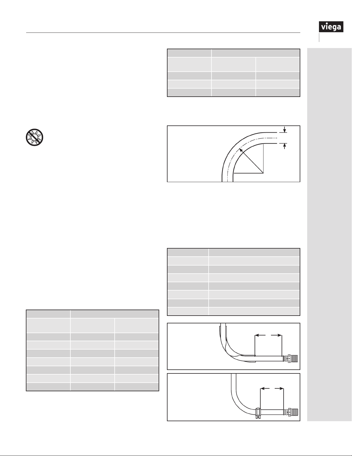
15 Installing the ViegaPEX Ultra Tubing System
15.1 Handling ViegaPEX Ultratubing
The properties of ViegaPEX Ultra tubing make it easy
to work with and install in most types of construction.
Some care must be taken to prevent damage to the
tubing before and during installation:
• Use care to protect both ViegaPEX Ultra and
FostaPEX tubing from physical damage during
storage and installation. Keep the tubing away from
sharp objects, open ames, etc., and do not place
heavy objects on the tubing.
• Damaged sections of tubing should be cut out
and discarded.
• Do not expose ViegaPEX Ultra tubing to
sunlight or any UV source for extended
periods of time exceeding six months.
• FostaPEX, with its aluminum layer, is resistant to UV
light, but long-term exposure should still be avoided.
• Do not store ViegaPEX Ultra or FostaPEX tubing
outdoors where it may be exposed to UV light.
15.2 Uncoiling ViegaPEX Ultratubing
An uncoiler should be used to preventtwisting when
removing tubing from ⅜" to 1" coils. Roll coils out and
use care to avoid twisting 1¼", 1½" and 2" coils or
when an uncoiler is unavailable.
15.3 Bending ViegaPEX Ultra tubing
ViegaPEX Ultra tubing can be free bent (unsupported
bend) to a minimum radius of eight times the tubing
O.D. and ve times the tubing O.D. with the use of
a Viega-approved bend support. FostaPEX tubing
can be free bent to a minimum radius of eight times
the tubing O.D. and 3.5 times the tubing O.D. with the
use of a Viega tubing bender. For situations requiring
tighter bends, use elbow ttings. If bending against
a PEX coil bend direction, the bending radius is 24
times the tubing O.D. Viega does not allow the practice
of “hot bending” ViegaPEX Ultra tubing to make a
tighter bend radius.
ViegaPEX Ultra Minimum Radius
Nominal Size*
⅜" 4" 2.5"
½" 5" 3.1"
¾" 7" 4.4"
1" 9" 5.6"
1¼" 11" 6.75"
1½" 13" 8.1"
2" 17" 10.6"
*ViegaPEX Ultra bend radius values were calculated
using standard CTS O.D. dimensions, which are ⅛" larger
than the nominal tube size listed.
Free Bend
(8 x O.D.)
Supported
(5 x O.D.)
FostaPEX Minimum Radius
Nominal Size**
½" 5.6" 2.4"
¾" 7.5" 3.3"
1" 9.6" 4.2"
** FostaPEX bend radius values were calculated using
the actual O.D. dimensions, which include the additional
aluminum and PE layers.
Minimum bending radius
for ViegaPEX Ultra
tubing
Free Bend
(8 x O.D.)
Radius
R
Supported
(3.5 x O.D.)
OD
Bend
To reduce damaging stress on Viega PEX ttings,
bend supports or tubing fasteners must be used
to anchor all bends made close to ttings. Support
must be provided for tubing bends located closer
to ttings than distance “L” in table below. (See the
diagrams below for typical installation examples.) Since
FostaPEX will maintain its shape once bent, supports
may not be necessary. However, support must be used
at the “L” distance while making the bend.
Tubing size Maximum distance from fitting to bend
⅜" PEX L = 6 inches
½" PEX L = 8 inches
¾" PEX L = 10 inches
1" PEX L = 12 inches
1¼" PEX L = 14 inches
1½" PEX L = 16 inches
2" PEX L = 18 inches
Using a bend support
near a Viega PEX
connection to reduce
stress on fitting
Using a tubing fastener
near a connection
to support bend and
reducestress on fitting
L
L
IM-PF 724596 0416
43
Page 44
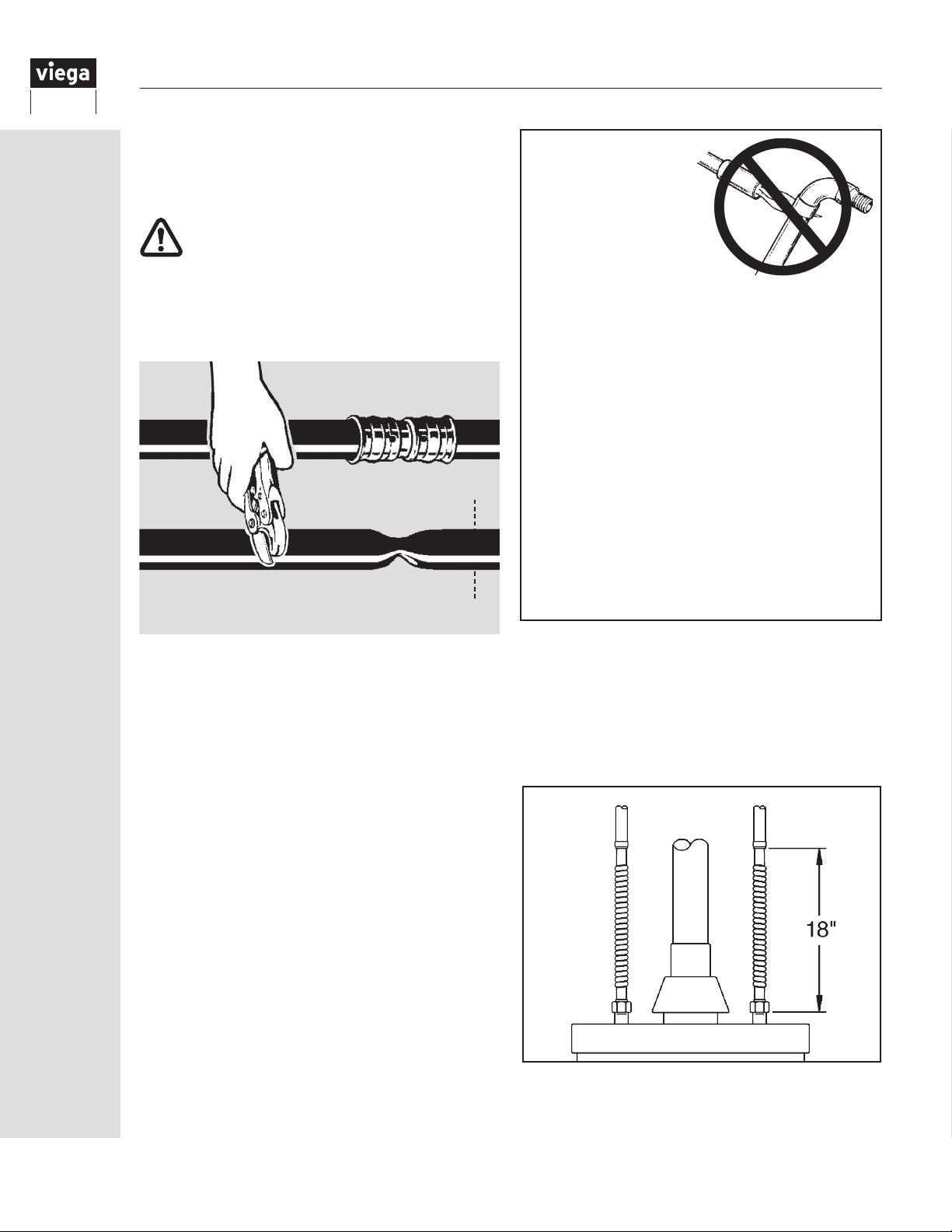
15.4 Removing Viega PEX connections
Should a mistake be made, simply cut out the PEX
tting and replace with a new one.
PEX tubing systems
should not be
intentionally subjected
to freezing.
Do not reuse Viega PEX fittings
15.5 Repairs
Sections of kinked tubing should be repaired by
cutting out the damaged section and installing a
repair coupling.
Inserting a coupling to repair kinked tubing
15.6 Freezing
The exibility of ViegaPEX Ultra tubing makes it
resistant to damage from freezing, but precautions
to prevent freezing should be taken when low
temperatures might be encountered.
Insulating each PEX tube individually or as a group is
not generally necessary if the PEX tubing is installed
within the insulation envelope of the structure, i.e. the
heated area. For example, the tubing may be installed
under the insulation in the attic or within an interior wall
of a heated space.
Do not use open torch
or excessive heat to
thaw PEX tubing. Tubing
failure or damage can result.
Heat (DO NOT USE A TORCH) must be applied
directly to the frozen tubing section. Temperature
on tubing shall not exceed 180°F.
Several suitable methods exist to thaw PEX
tubing:
• Hot water
• Wet, hot towels
• Handheld hair dryer
• Low-wattage electrical heating tape (self limiting)
• A commercial system that pumps heated water
through a tube to the ice blockage and returns
the cooled water for reheating
ViegaPEX Ultra may be used to connect to
instantaneous/tankless water heaters or other hot water
producing devices. However, consult manufacturer’s
recommendations for use with plastic tubing and
ensure temperature and pressure do not exceed the
maximum ratings of the tubing.
15.7 Water heaters
ViegaPEX Ultra tubing should not be connected directly
to gas-red water heaters. The high temperatures of
these appliances can damage the tubing.
When connecting a Viega PEX system to a gas-red
water heater, install a minimum of 18" of metallic piping
between the water heater and tubing, keeping tubing
more than 6" away from the vent pipe. Where local
code allows, ViegaPEX Ultra tubing may be connected
directly to electric water heaters and used for hot water
recirculation lines that do not come within 6" of the gas
heater vent.
44
A minimum of 18" of metallic piping is required
between a gas-fired water heater and PEX tubing.
IM-PF 724596 0416
Page 45
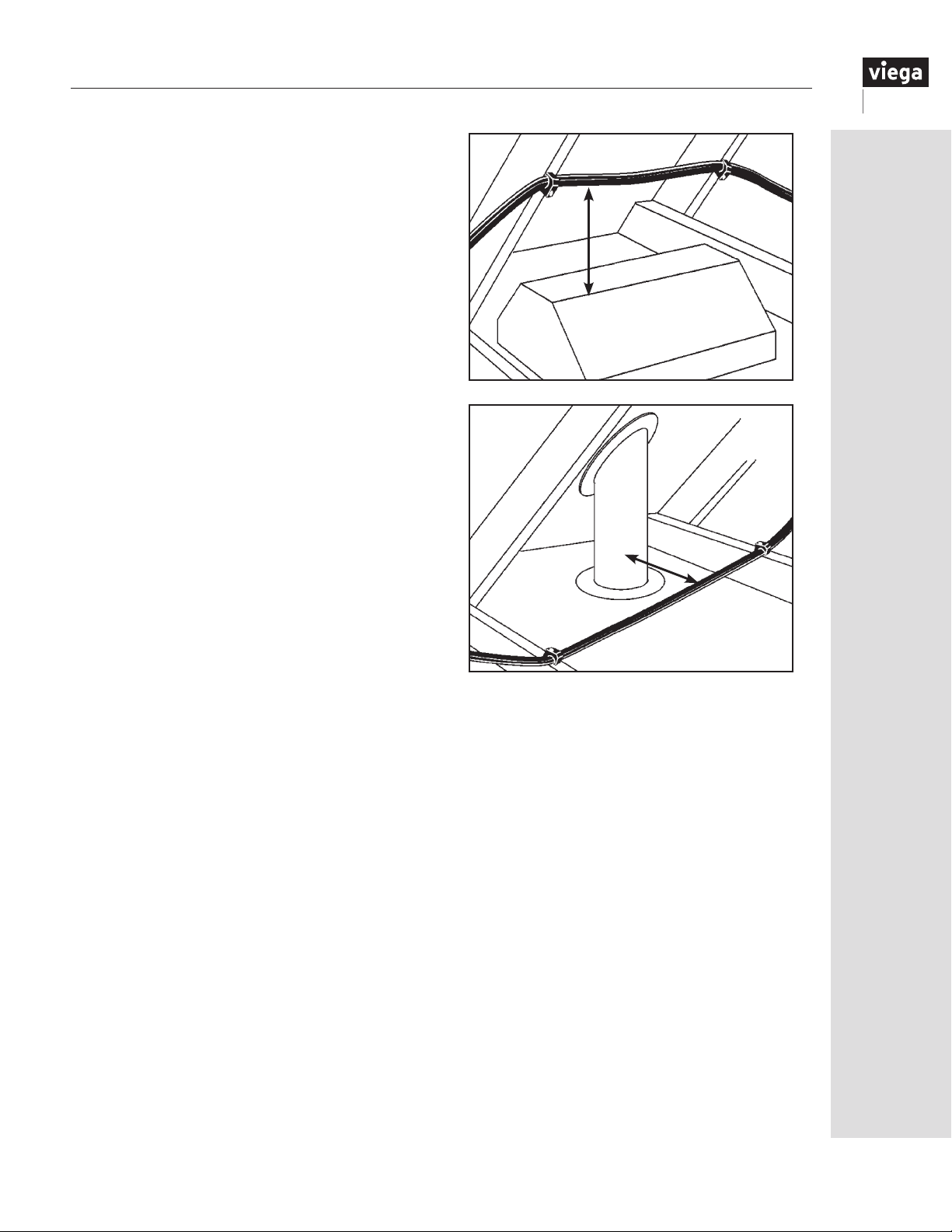
15.8
Heaters, flues, vents and recessed lights
Keep ViegaPEX Ultra tubing a MINIMUM of 12"
vertically and 6" horizontally from sources of high
heat such as gas ue vents, heating appliances or
electric motors. Concerning recessed lighting (including
low-voltage types) and proper installation clearance,
Viega recognizes the following types of lighting xtures:
Type IC or Inherently Protected, which allow direct
contact with thermal insulation and other combustible
materials, and Type Non-IC, which require a minimum
clearance of 3" to thermal insulation. If room does not
allow for the minimum clearance spacing specied by
Viega, then the PEX tubing must be insulated with a
suitable pipe insulation capable of withstanding the
specic maximum temperatures generated by the
xture. Minimum clearance between any pipe insulation
and xture shall be per the requirements of the xture
type and local building codes.
Forced air heating ducts and PVC power vent ues
are not generally considered sources of high heat.
These areas of installation should be rechecked after
further construction and other mechanical systems
have been installed.
In cases where light leakage (direct beam) from a
UV-generating light source (special lighting or heatingtype lamps) is possible, tubing must be adequately
protected with light-blocking insulation.
12" minimum
6" minimum
Maintain a minimum 12" of vertical and 6" of
horizontal clearance from recessed lights and
appliance or heater vents.
IM-PF 724596 0416
45
Page 46
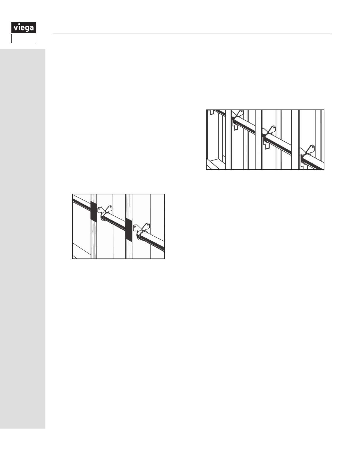
16 Fastening the Viega PEX System
16.1 Wood frame construction
ViegaPEX Ultra and FostaPEX tubing are ideal for use
in wood frame construction. The ability to bend the
tubing around corners and obstacles greatly simplies
installation. This system eliminates the expensive and
time-consuming use of ttings where tubing turns
within a wall, and eliminates the potential re hazard of
soldering close to exposed framing members.
A few rules should be followed when running
ViegaPEX Ultra tubing in wood frame construction:
• Use nailing plates to protect the tubing from nails and
screws where it passes through studs
• Suspension clips are required for metal studs and
optional for wooden studs
• When turning tubing sharply to exit from a wall, a
bend support must be provided. Either use a dropear bend support, drop-ear elbow or a stub out.
Neglecting to use a support will place excessive
stress on the tting, and the tubing will not exit
perpendicular to the wall (except FostaPEX).
16.2 Steel construction
The Viega PEX system works as well in steel frame
construction as it does in wood. Where tubing runs
through metal studs, suspension clip fasteners must
be used to protect tubing from sharp stud edges.
(Seeillustration below.) Follow the same guidelines for
fastening and supporting the tubing as for wood frame
construction.
Suspension clip fasteners used to protect tubing from
abrasion when passing through steel studs
Nailing plates protect tubing passing
through studs and joists from nails.
46
IM-PF 724596 0416
Page 47
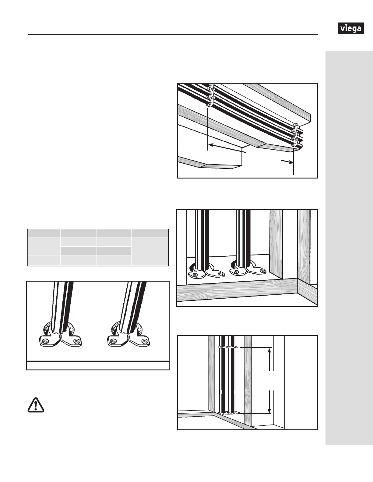
16.3 Supporting ViegaPEX Ultratubing
Use only plastic or plastic-coated tubing supports.
Metal supports may damage tubing.
When running tubing, leave a small amount of slack
between fasteners to account for tubing contraction.
Note that ViegaPEX Ultra tubing will expand or contract
1.1" per 100' for every 10°F of temperature change.
Inlong straight runs, allow adequate clearance for
this. (See “16.9 Tubing expansion” on Page 48.) The
aluminum layer in FostaPEX reduces expansion and
contraction, so that it expands only 0.16" per 100' for
every 10°F of temperature change. This makes it ideal
for locations where expansion must be minimized.
Tubing should be allowed freedom to move slightly
as it expands. Do not clip it tightly into place or locate
it where it will be tightly constrained. Use suspension
clips or an approved plastic insulator where tubing
passes through studs or joists where abrasion and
noise is a concern. (See illustrations to right.)
ViegaPEX Ultra tubing must be fastened at a minimum
interval noted in the table below for vertical and
horizontal support.
In risers or vertical runs, ViegaPEX Ultra and FostaPEX
tubing should be attached with suspension clips or
an approved plastic insulator at each oor or ceiling
penetration, and every four feet in between (see below).
Spacing per
Table 16.1
Tubing supported with U-clip or lock clip fasteners on
horizontal runs
PEX Size Horizontal Vertical
ViegaPEX
Ultra
FostaPEX ½" - 1" 32" O.C.
½" - 1" 32" O.C. Base of each
1¼" - 2" 48" O.C.
oor with
mid-level
guide
Table 16.1 PEX Support
Suspension clips support tubing in joist penetrations
or anywhere abrasion is a concern.
Some model codes may allow greater
support spacing intervals for plastic tubing.
Always refer to local code for approved
spacing requirements that exceed the ones
referenced in this manual.
Suspension clip fasteners used at floor plate
Midlevel
Guide
J-clamp or lock clip fasteners used to support tubing
in vertical runs between floors
IM-PF 724596 0416
47
Page 48
16.4
Noise and water hammer in PEX systems
As with all plumbing materials under some
operating conditions, water hammer can occur in
PEX plumbing systems. The inherent exibility of
ViegaPEX Ultra drastically reduces the magnitude of
pressure surges compared with metallic plumbing
materials. Damage to plumbing components in a
PEX system due to these pressure surges is highly
unlikely, although noise can sometimes result.
Fortunately, there are solutions to minimize or
eliminate water hammer noise.
• Install xtures that are not water hammer prone.
As a general rule, two-handle xtures are less likely
to cause hammer than single-handle xtures. Singlehandle shower valves, which rotate to close and
therefore are difcult to close quickly, might be
good choices.
• Clamping or strapping more frequently may help
prevent tubing noise. It is important that the tubing
not be in contact with wallboard, forced air ducts
or other high-resonance articles. Insufciently
or improperly clamped or strapped tubing may
move during xture operation and hit against
these surfaces.
• Install a water hammer arrester at xtures where
noise is a problem. A water hammer arrester (AA
sized) installed as closely as possible to the xture
on the cold-water side only will eliminate the source
of the noise (the pressure wave). It should be noted
that even with an arrester, tubing that is clamped or
strapped insufciently may still hit against something
as it moves slightly when the water ow is stopped.
• Avoid operating xtures in such a way that causes
near instantaneous shutoff. Simply closing xtures in
a less abrupt manner can eliminate hammer noise.
When using expanding spray foam to insulate
walls in a structure, there are several options
available. Viega suggests using water-based or
urethane-based open-cell insulation only. DO NOT use
closed-cell spray foams. Closed-cell spray foams have
the potential to generate high temperatures during their
expansion process, especially when not applied
properly, which can damage PEX tubing. Always follow
the spray foam manufacturer’s installation instructions
and warnings.
Do not expose Viega products to any
foreign substance that includes but is
not limited to Volatile Organic Chemical
(VOC) compounds, paints, solvents,
glues, cleaners and disinfectants. Viega
products that are exposed to these
types of substances are at risk of having
failures (leaks).
16.8 Fire Stop compounds
Most building codes require the use of a restopping compound when tubing penetrates a
re-rated wall. There are a number of re-stopping
compounds identied as water based, acrylic or
latex that have been listed for use with PEX tubing
that include but are not limited to the following.
• 3M Fire Protection — CP 25WB+ Caulk
• Tremco, Inc — TREMstop® IA
• Specied Technologies, Inc. — SpecSeal®
SSS 100 / SSS 102
•
Passive Fire Protection Partners — Fire Stop™
4800 DW / 4100 DW / 4100 NS / 3600 EX
16.5 Shower valves
PEX lines should only be run to the inlet connections of
tub/shower valves unless specically approved by the
valve manufacturer for other connections.
16.6 Electrical grounding
Neither ViegaPEX Ultra nor FostaPEX tubing may be
used as an electrical ground. Consult the NEC for
recommended
is used.
grounding method when plastic pipe
16.7 Expanding foams
When penetrations must be sealed for air inltration
purposes, there are several options available. Use a
good grade of silicone, acrylic or siliconized acrylic
caulking. DO NOT use oil-based caulks. Most
canned expanding foams and open- or closed-cell pipe
insulation are good sealing materials and may be used
in direct contact with PEX tubing. Other materials may
be used provided they do not cause short- or long-term
damage to the PEX tubing.
48
It is the responsibility of the user to determine
the suitability of these or any products for the
intended application and install the compounds
in accordance with the product’s installation
instructions and listing.
16.9 Tubing expansion
ViegaPEX Ultra tubing, as with any PEX tubing,
expands and contracts with temperature changes
in the environment or the fluid inside the tubing.
The longer the tubing run and the higher the
temperature change, the more linear expansion
the system will experience. This expansion and
contraction can affect the appearance as well as
integrity of the system by putting stress on the
tubing, fittings, valves and fasteners.
IM-PF 724596 0416
Page 49
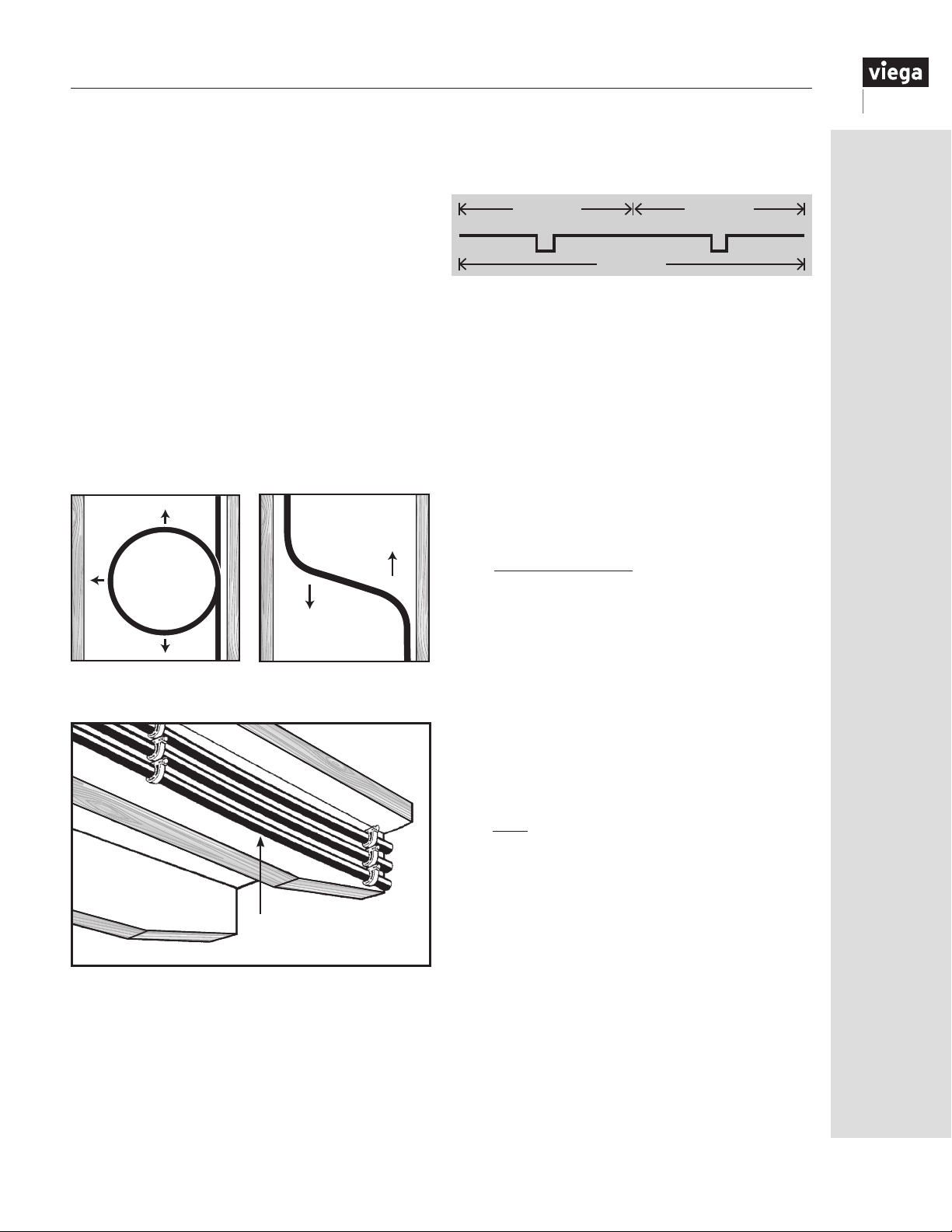
Tubing fasteners perform two functions: providing
support for the tubing and guiding the tubing during
expansion and contraction. It is important to keep
this in mind when installing fasteners. An expansion
compensator will not be effective if the fasteners
prevent linear movement of the piping system.
Tubing sizes smaller than ¾" generally do not
require expansion compensators with fittings and
can easily be bent into loops and offsets to absorb
linear expansion. Tubing sizes 1" and larger, refer
to “16.9.1 Calculating expansion loops and offsets”
for compensation options.
For unconstrained tubing runs (not within the floor)
Viega recommends the use of expansion offsets.
This can be accomplished at a corner or by using
offsets or loops on straight tubing runs. Expansion
compensators should be installed at the midway point
of tubing runs and should be spaced no more than
50 feet apart.
Below is an example of required offsets for a 100-foot
tubing run. Note that the expansion compensators are
no more than 50 feet apart.
50' 50'
25'25' 50'
100'
16.9.1 Calculating expansion loops and offsets
There are three types of expansion offsets
recommended for use with large-diameter tubing:
the corner expansion offset, the Z-type expansion
offset and the U-type expansion loop. A description,
illustration and dimensions chart for each type of
offset is on the next few pages. See “FostaPEX” on
Page 53 for FostaPEX recommendations.
Linear expansion:
To calculate linear expansion for PEX tubing, use
the following formula:
Using a loop to accommodate
tubing expansion
Allow some slack in all runs to prevent
damage from tubing contraction.
Offsets also provide room for
tubing expansion.
⅛" to 3/16"
slack per foot
PEX expansion rate
∆L =
100' x 10°F
x ∆T x LT
Where:
ViegaPEX Ultra expansion rate = 1.1" per 100' per
10°F
∆T = Change in temperature (in °F)
LT = Length of tube between fixed points (in ft.)
For example:
40' of 1" ViegaPEX Ultra tubing going from 70°F to
130°F
1.1"
∆L =
x 60° x 40' = 2.64"
1000
∆L = 2.64"
IM-PF 724596 0416
49
Page 50
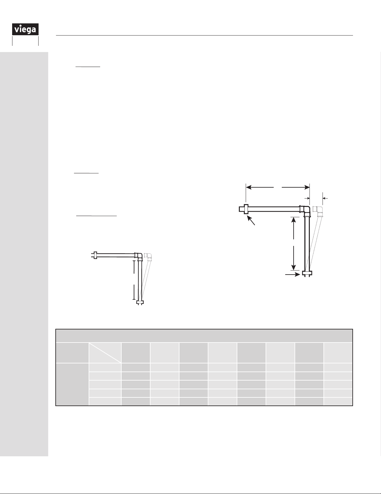
Compensation distance:
To calculate the dimensions of the expansion compensation offset needed, use the following formula:
L = C√OD x ∆L
Where:
L = length of compensation distance
C = 12 (PEX material specic constant)
OD = outer tubing diameter (⅛" + nominal tube size)
∆L = change in length from temperature change
Corner expansion offset:
Where piping takes a corner after a long straight run, a simple 90° elbow in the piping will allow for the
absorption of expansion.
Calculate the necessary “L” dimension between elbow and nearest fastener or use the chart below,
which was gured using the maximum run for a single expansion compensator (50 feet).
Following the previous example:
L = C√OD x ∆L
Where:
C = 12
OD = 1.125 (1" PEX)
LT
∆L
∆L = 2.64"
L = 12√1.125" x 2.64" = 20.7"
L = 20.7"
Anchor Point
Illustration of Example
L = 20.7"
Figure 16.1 Corner Expansion
Tubing
ViegaPEX
&
ViegaPEX
Ultra
∆T(°F)
Tube
nom.
¾" 20.4 23.6 26.4 28.9 31.2 33.4 35.4 37.3
1" 23.2 26.7 29.9 32.8 35.4 37.8 40.1 42.3
1¼" 25.6 29.6 33.1 36.2 39.1 41.8 44.4 46.8
1½" 27.8 32.1 35.9 39.4 42.5 45.5 48.2 50.8
2" 31.8 36.8 41.1 45.0 48.6 52.0 55.1 58.1
Table 16.2 Corner Expansion
L
Anchor Point
Corner Offset
Corner Expansion Offset (L, in)
per 50 linear feet of run
60 80 100 120 140 160 180 200
50
IM-PF 724596 0416
Page 51
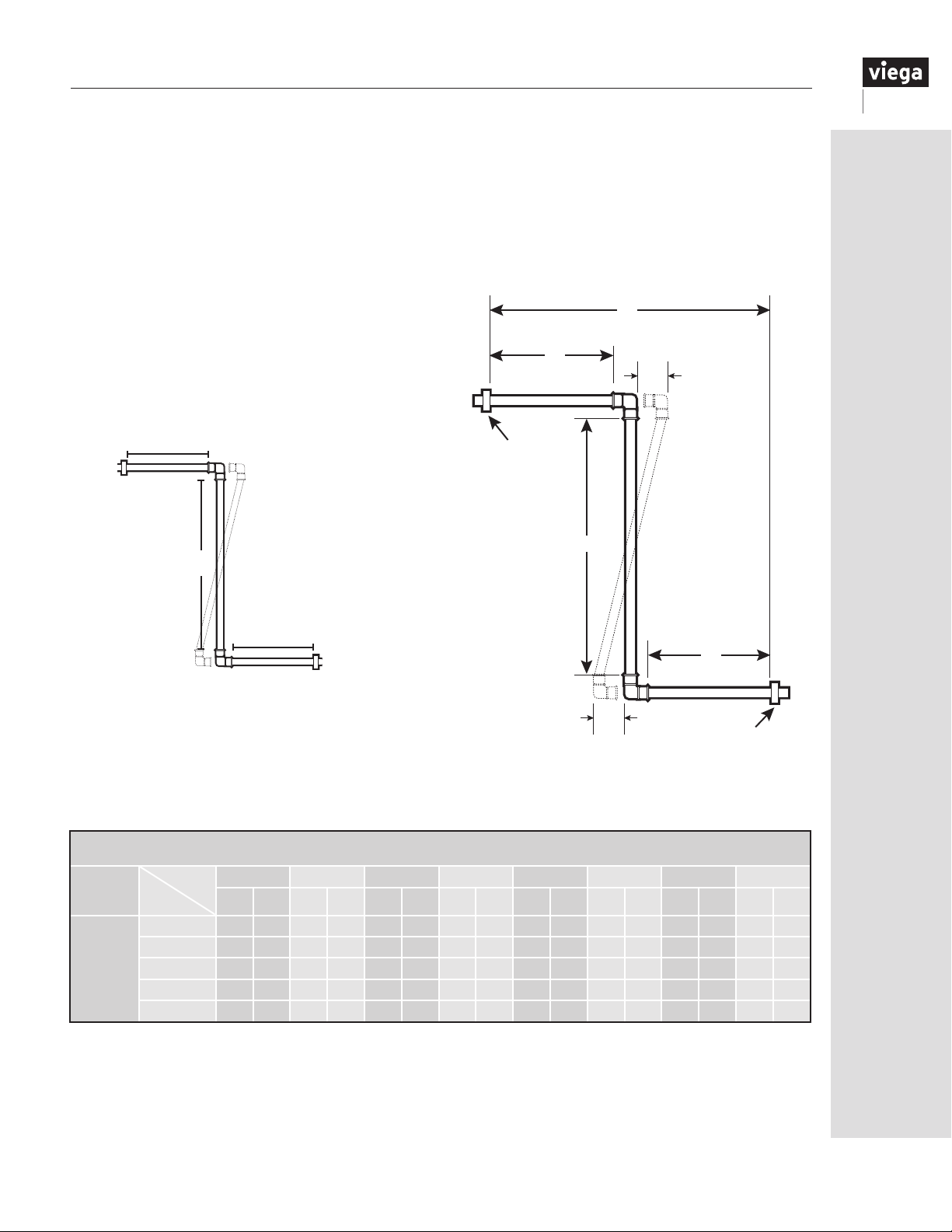
Z-type expansion offset:
The Z-type expansion offset integrates two 90° elbows that form a “Z” pattern.
With this type of configuration ½ of the “L” dimension is applied to the center area of the “Z” (represented
as L1 in the table and illustration) while ¼ of the “L” dimension would be applied to each of the top and
bottom areas (represented as L2).
Calculate the necessary L1 and L2 dimensions or use the chart below, which was figured using the
maximum run for a single expansion compensator (50 feet).
L = 20.7"
L1 = ½ (L)
L1 = 20.7"/2 = 10.35"
LT
L1 = 10.35"
L2 = ¼ (L)
L2 = 20.7"/4 = 5.18"
L2 = 5.18"
L2
∆L
Illustration of Example
L2 = 5.18"
L1 = 10.35"
Anchor Point
L1
L2 = 5.18"
Figure 16.2 Z-Type Expansion
Tubing
ViegaPEX
&
ViegaPEX
Ultra
∆T(°F)
Tube
nom.
¾" 10.2 5.1 11.8 5.9 13.2 6.6 14.4 7.2 15.6 7.8 16.7 8.3 17.7 8.8 18.6 9.3
1" 11.6 5.8 13.4 6.7 15.0 7.5 16.4 8.2 17.7 8.8 18.9 9.5 20.1 10.0 21.1 10.6
1¼" 12.8 6.4 14.8 7.4 16.5 8.3 18.1 9.1 19.6 9.8 20.9 10.5 22.2 11.1 23.4 11.7
1½" 13.9 7.0 16.1 8.0 18.0 9.0 19.7 9.8 21.3 10.6 22.7 11.4 24.1 12.1 25.4 12.7
2" 15.9 8.0 18.4 9.2 20.5 10.3 22.5 11.3 24.3 12.2 26.0 13.0 27.6 13.8 29.1 14.5
60 80 100 120 140 160 180 200
L1 L2 L1 L2 L1 L2 L1 L2 L1 L2 L1 L2 L1 L2 L1 L2
Table 16.3 Z-Type Expansion
Z- Type Expansion Offset (in)
per 50 linear feet of run
∆L
Z-Type Offset
L2
Anchor Point
IM-PF 724596 0416
51
Page 52
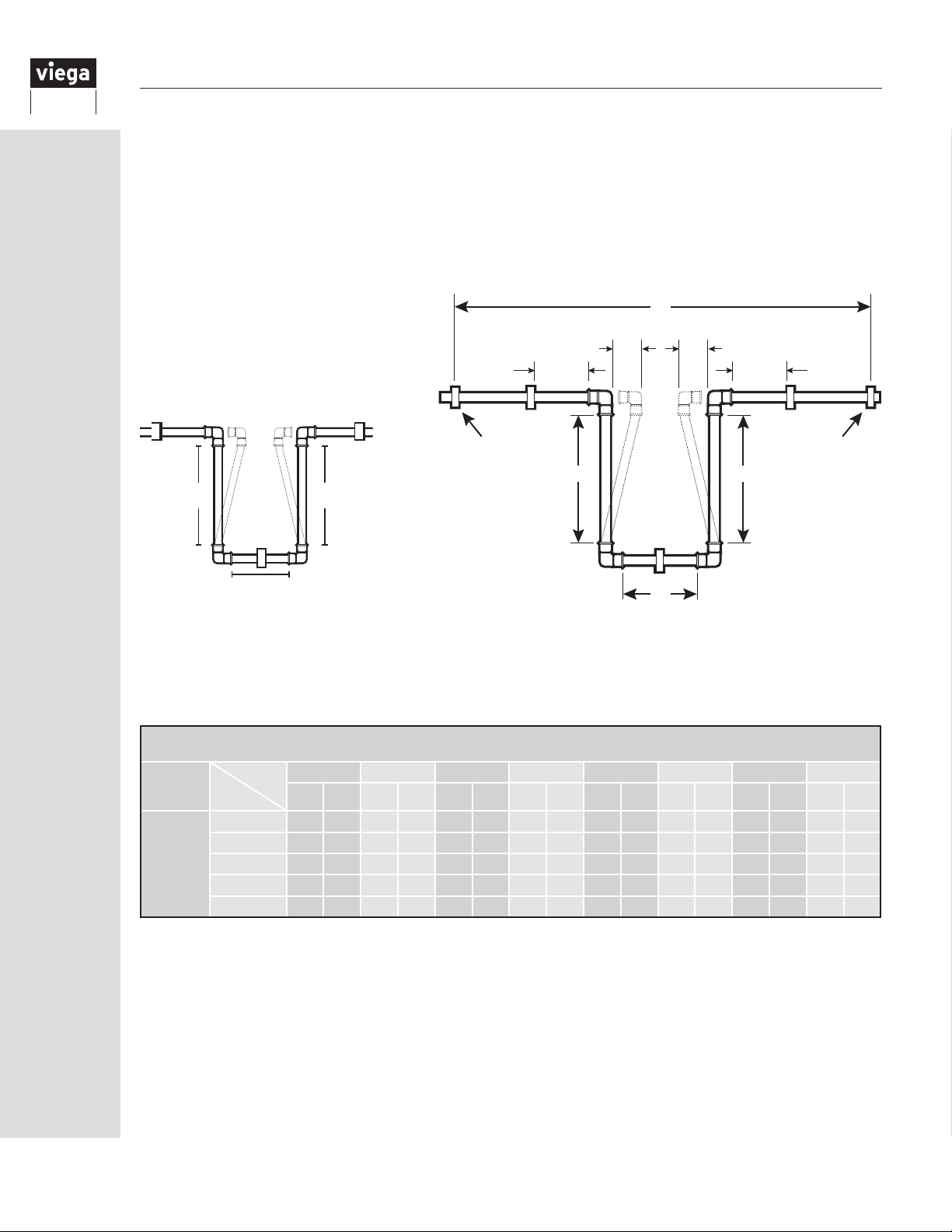
U-type expansion offset:
The U-type expansion loop integrates four 90° elbows that form a “U” pattern.
With this arrangement ⅕ of the “L” dimension is applied as the width (represented as L3) while ⅖ of “L” is
applied as each leg in the other dimension (represented as L4).
Calculate the necessary L3 and L4 dimensions or use the chart below, which was gured using the
maximum run for a single expansion compensator (50 feet).
L = 20.7"
L3 = ⅕ (L)
L3 = 20.7"/5 = 4.14"
L3 = 4.14"
L4 = ⅖ (L)
L4 = 2(20.7")/5 = 8.28"
L4 = 8.28"
4 - 6" 4 - 6"
LT
∆L/2 ∆L/2
Illustration of Example
Anchor Point Anchor Point
L4L4
L4 = 8.28"
L4 = 8.28"
L3 = 4.14"
L3
Figure 16.3 U-Type Expansion
Looped Offset
The fastener shown on the L3 leg may be required to provide additional support depending on how the expansion loop is installed
(horizontal/vertical).
U-Type Expansion Offset (in)
per 50 linear feet of run
Tubing
ViegaPEX
&
ViegaPEX
Ultra
∆T(°F)
Tube
nom.
¾" 4.1 8.2 4.7 9.4 5.3 10.5 5.8 11.6 6.2 12.5 6.7 13.3 7.0 14.2 7.5 14.9
1" 4.6 9.3 5.3 10.7 6.0 12.0 6.6 13.1 7.1 14.2 7.6 15.1 8.0 16.0 8.5 16.9
1¼" 5.1 10.2 5.9 11.8 6.6 13.2 7.2 14.5 7.8 15.6 8.4 16.7 8.9 17.7 9.4 18.7
1½" 5.6 11.1 6.4 12.9 7.2 14.4 7.9 15.7 8.5 17.0 9.1 18.2 9.6 19.3 10.2 20.3
2" 6.4 12.7 7.4 14.7 8.2 16.4 9.0 18.0 9.7 19.5 10.4 20.8 11.0 22.1 11.6 23.2
Table 16.4 U-Type Expansion
60 80 100 120 140 160 180 200
L3 L4 L3 L4 L3 L4 L3 L4 L3 L4 L3 L4 L3 L4 L3 L4
52
IM-PF 724596 0416
Page 53
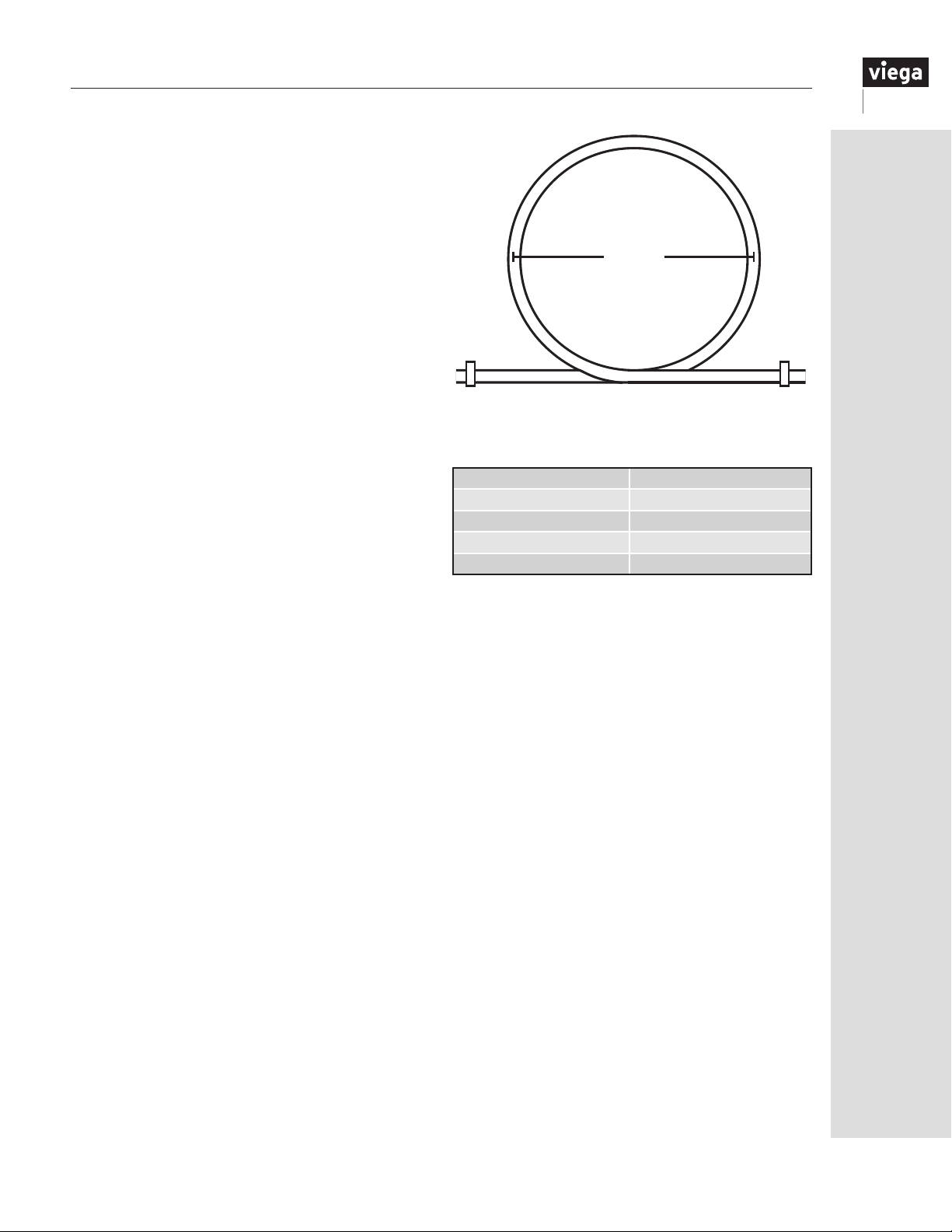
FostaPEX:
FostaPEX tubing has a fully dimensional PEX wall
with an additional outer layer of aluminum and
polyethylene. As a result of these extra layers,
FostaPEX expands considerably less than that of
standard PEX tubing and slightly more than copper
tubing (0.16" per 100' per 10°F).
An approved method for expansion absorption
when using FostaPEX is through the use of a coiled
loop expansion compensator (at least every 50
feet). Do not use fitting offsets with FostaPEX as
the stiffness of FostaPEX may lead to high stress
at connections.
Coiled loop:
The coiled loop configuration calls for loops within
the piping system. The diameter of the loop (D) is
shown in the table and will increase or decrease as
the tubing in the system expands and contracts.
Note: Tubing fasteners should be secured as to not
prevent linear movement of tubing.
D
Figure 16.4 Coiled Loop Expansion
Tube nom. D (in)
½" FostaPEX 12"
⅝" FostaPEX 14"
¾" FostaPEX 16"
1" FostaPEX 20"
Table 16.5 Coiled Loop Expansion
IM-PF 724596 0416
53
Page 54
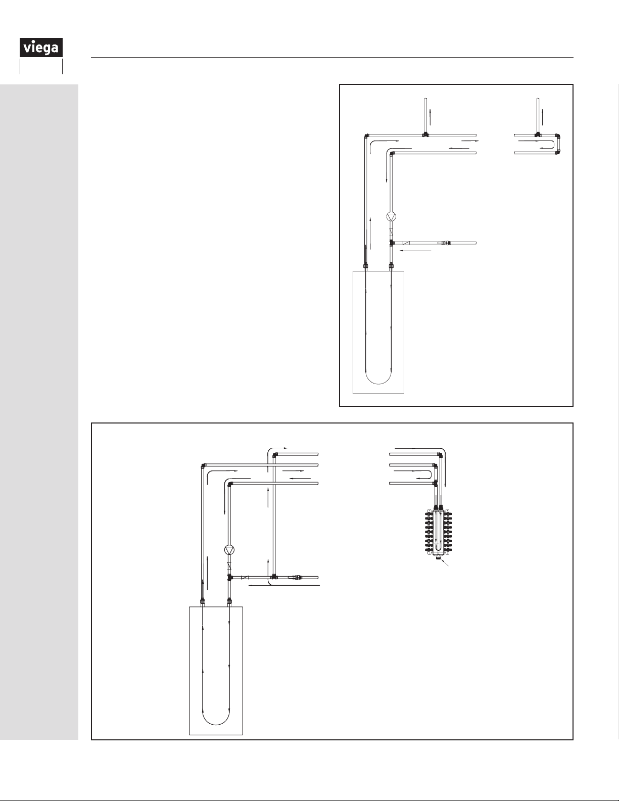
16.10
Domestic hot water circulating systems
A hot water circulation system can be incorporated
into most plumbing systems and works by
constantly (or periodically throughout the day on
a timer) circulating hot water through the main hot
supply line of your plumbing system.
This is done by using a return line at the end of the
main hot supply line, and a low-flow pump (usually
near the hot water tank). The circulating system keeps
hot water readily available throughout the main hot
water supply line, eliminating the need to purge the
entire line before hot water is present at the fixture.
There are a number of hot water circulation systems
available in the marketplace that offer a variety of
options. These systems are ideal for branch-andmain
or combination systems with spread-out fixture
groups/
floor plans, as well as for larger homes using
multiple ManaBlocs in a parallel-type system.
ViegaPEX Ultra can be used in recirculating domestic
hot water plumbing loops, provided:
1. The plumbing loops shall operate with water
temperatures of 140°F or lower, as required by most
model plumbing codes.
2. The recirculating loop is for supplying hot water more
quickly to the xture.
3. The tubing is marked as rated for “continuous
recirculation” as evidenced by the ASTM F876
certication marking PEX 5306 (CL5).
To Fixture
Hot Water Supply
Hot Water Supply
Circ Pump
Check Valves
Cold Supply to W/H
Hot
Cold
Water Heater
Typical domestic hot water circulation piping
To Fixture
Hot Return
Continuously Recirculating Hot Water Plumbing Loops
Cold Water Supply
Hot Water Supply
Hot Return
If the ManaBloc must be
mounted farther than 8 ft. from
the hot water source, the
ManaBloc may be supplied
from a domestic hot water
circulating loop using ViegaPEX
Ultra tubing.
Cold Water Supply
End Cap
Hot Water Supply
Hot
Circ
Pump
Check
Valves
Cold Supply to W/H
Cold
54
Water Heater
IM-PF 724596 0416
Page 55
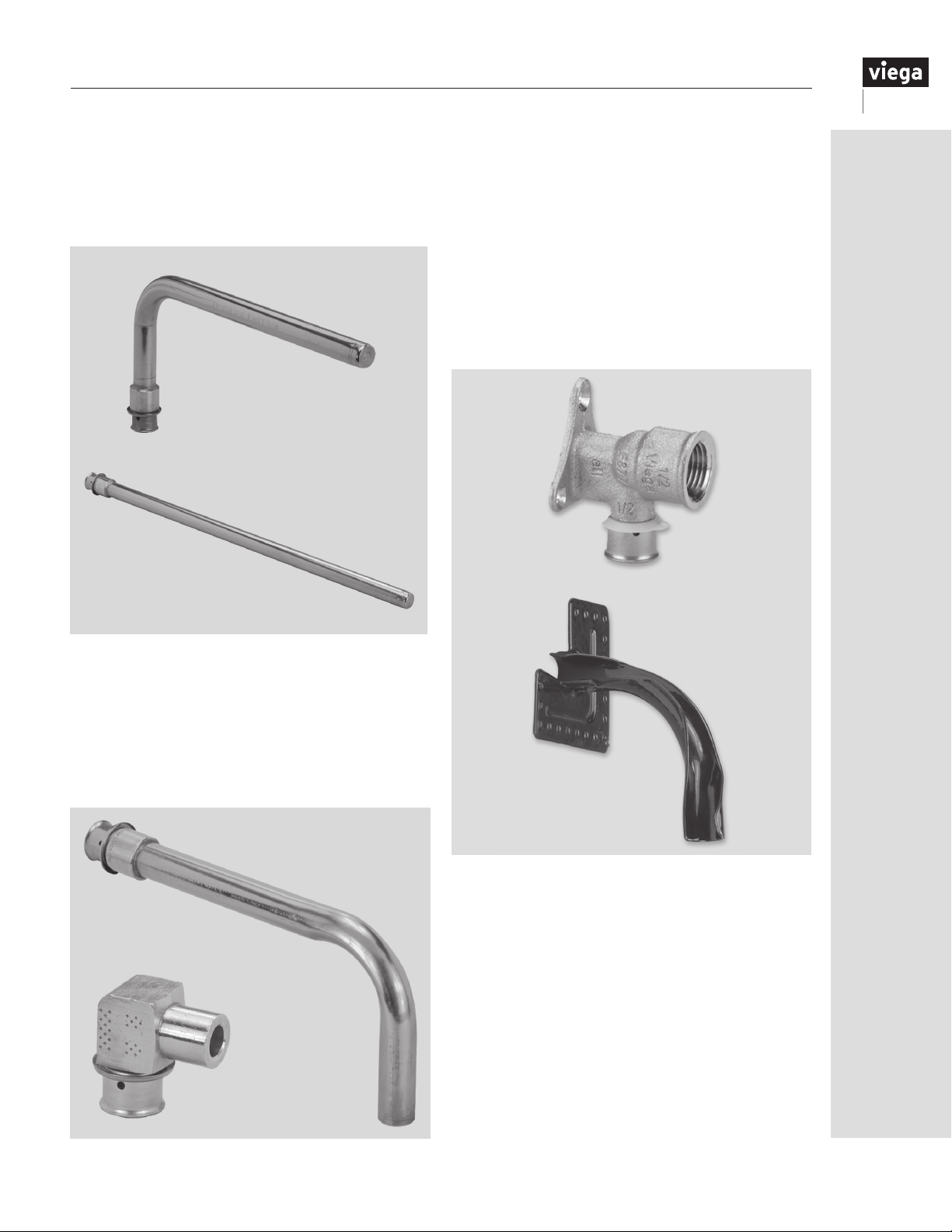
17 Installing Viega PEX Fittings
17.1 Stub out options
The Viega PEX system includes ttings to
accommodate most plumbing needs. Stub outs are
available for a variety of xture situations, as well
as ttings and valves to connect to other plumbing
materials and xtures.
Copper Stub Out
Copper Straight Stub Out
Drop-ear elbows provide a ½" or ¾" F NPT threaded
connection at a wall or oor penetration as well as a
ange for securing the tting.
Drop-ear bend supports allow ViegaPEX Ultra tubing to
be directly stubbed out of a wall. These supports allow
the tubing to make the tight bend necessary to exit
the wall at a 90° angle as well as providing aange for
securing the support.
The exposed tubing can then be connected to a valve,
using an optional chrome sleeve to cover the tubing if
desired.
Drop Ear
Elbow
Standard stub outs with 90° bends and a closed end
to facilitate pressure testing are available in either ⅜"
or ½" PEX x ½" copper.
Also, PEX Press copper tub elbow and PEX Crimp
shower valve adapters are available for easy
connections to tub and shower valves.
Copper Tub Elbow
Shower
Valve Adapter
Drop Ear
Bend
Support
IM-PF 724596 0416
55
Page 56
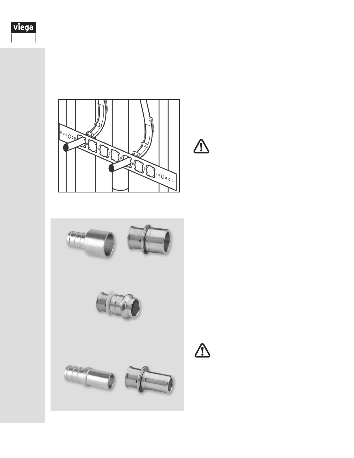
Half-inch snap-in bend supports are also available with
a metal mounting bracket (sold separately) for quick
and easy stub outs with ½" ViegaPEX Ultra tubing.
Seven stub out locations and numerous nail holes
make this a versatile option for stubbing out any
number of lines or supporting tubing near manifolds.
Snap-in Bend Supports with Bracket
Copper Tubing Adapters
Press ProPress Adapter
17.2 Copper connections
Fittings are available to adapt ViegaPEX Ultra tubing to
both copper tubing and copper ttings. Copper tubing
adapters slip over copper tubing to provide a sweat
connection. Always make the sweat connection to the
tting before connecting PEX to avoid heat damage to
the tubing.
Copper tting adapters t into copper ttings to
mate PEX to standard sweat or ProPress ttings. As
with copper tubing adapters, always make sweat
connections prior to PEX connection to avoid tubing
damage.
PEX Crimp fitting adapters are not for use
with the Viega ProPress connection.
17.2.1 Soldering Zero Lead alloy PEX fittings
Viega’s Zero Lead PEX ttings are manufactured
from alloys known for their low lead content and
corrosion-resistant properties. These alloys have
lower thermal conductivity compared to standard
(leaded) alloys, which tends to make them more
sensitive to soldering conditions. It is important to
follow the steps below to ensure consistent leakfree solder connections.
Prepping and cleaning
Zero Lead alloys are harder than standard alloys.
Cleaning and prepping the Zero Lead solder joint
area with an abrasive product like emery cloth,
sandpaper or wire brush is an important step in
the solder process. Do not rely on ux alone. This
surface preparation removes the natural oxidative
barrier that tends to form on Zero Lead alloys.
Once this is done, uxing and soldering should be
done immediately to ensure the oxide lm does not
reform on the freshly cleaned surface.
Use of proper flux and solder
Only use ux containing chloride compounds.
Solder uxes without chloride compounds are
not recommended for use on Zero Lead alloys.
56
Only lead-free solder should be used to
make Zero Lead solder connections.
Copper Fitting Adapters
IM-PF 724596 0416
Page 57
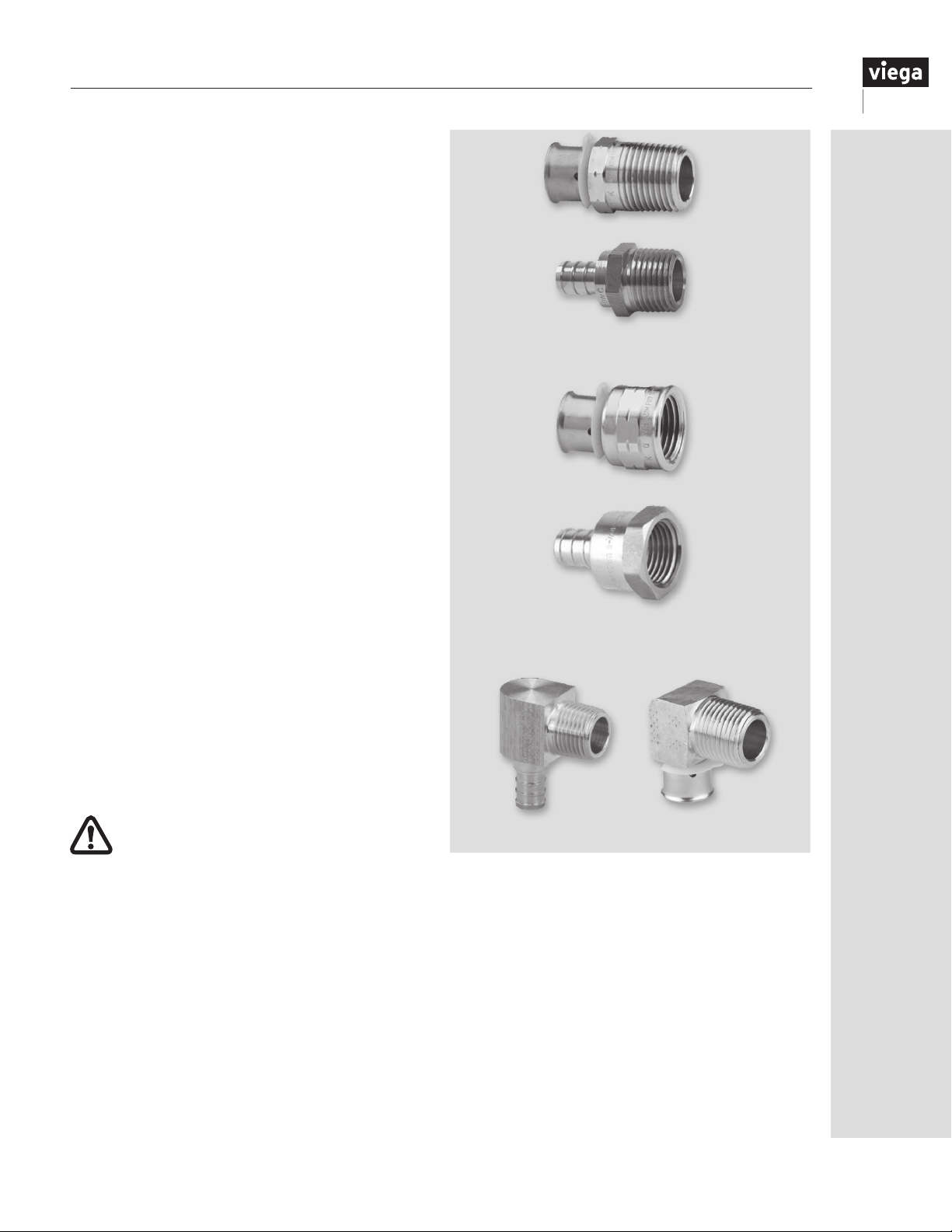
Heating
Like standard (leaded) alloys, heating of the
Zero Lead solder joint should be done evenly
and gradually using an appropriately sized tip
with constant movement of the ame over the
joint. Be careful not to overheat the Zero Lead
alloy while making a solder joint. Overheating
will result in a brown discoloration of the metal,
which is an indication that ux has burned out of
the solder joint, potentially causing incomplete
solder coverage. If you suspect this has occurred,
disassemble the joint, clean and repeat the process
using proper heating techniques.
Proper Cool Down
Because Zero Lead alloys have a lower thermal
conductivity than standard alloys they do not
cool down as quickly after making a solder
connection. If excessive heating has occurred and
an accelerated cooling process is required, apply
a damp cloth to the freshly completed solder joint.
This will help minimize the risk of the solder joint
moving or leaking solder out of the joint before the
joint can cool.
Male Adapters
17.3 Threaded connections
The Viega PEX system also provides a number of
ttings to adapt ViegaPEX Ultra and FostaPEX tubing
to NPT threads.
In addition to the NPT drop-ear elbows already
mentioned, metallic male and female adapters and
male NPT elbows provide threaded connections.
The threaded connection should always be made
before the PEX connection to avoid twisting the
PEX connection.
Do not use metallic threaded adapters when
connecting to polymer threads.
Female Adapters
NPT Elbows Adapters
IM-PF 724596 0416
57
Page 58
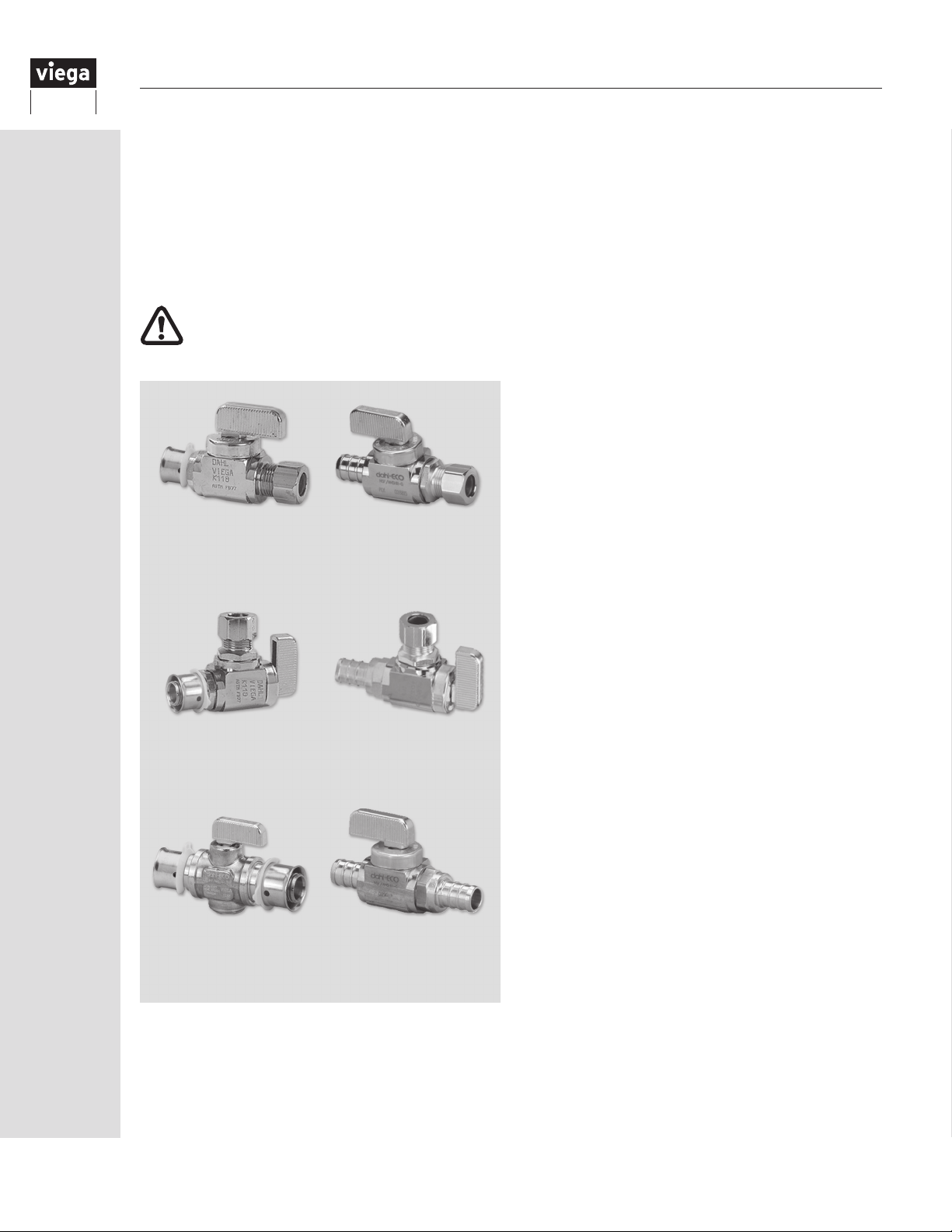
17.4 Valves
In-line ball valves are available foruse with ViegaPEX
Ultra tubing. These brass nish valves may be used
anywhere an in-linevalve is needed.
Stop valves have ⅜" or ½" PEX inlets and ¼"
CTS (⅜" O.D.) riser outlets and are available in
both straight and angled versions depending on
installation requirements.
Only plastic ferrules should be used when
connecting to PEX tubing/risers. Brass
ferrules are for use with copper tubing.
¼-Turn Straight Stop
Valve PEX Press to ⅜"
O.D. Riser
¼-Turn Angle Stop
Valve PEX Press to ⅜"
O.D. Riser
In-line Ball Valve (Press)
¼-Turn Straight Stop
Valve PEX Crimp to
⅜" O.D. Riser
¼-Turn Angle Stop
Valve PEX Crimp to
⅜" O.D. Riser
In-line Ball Valve (Crimp)
58
IM-PF 724596 0416
Page 59
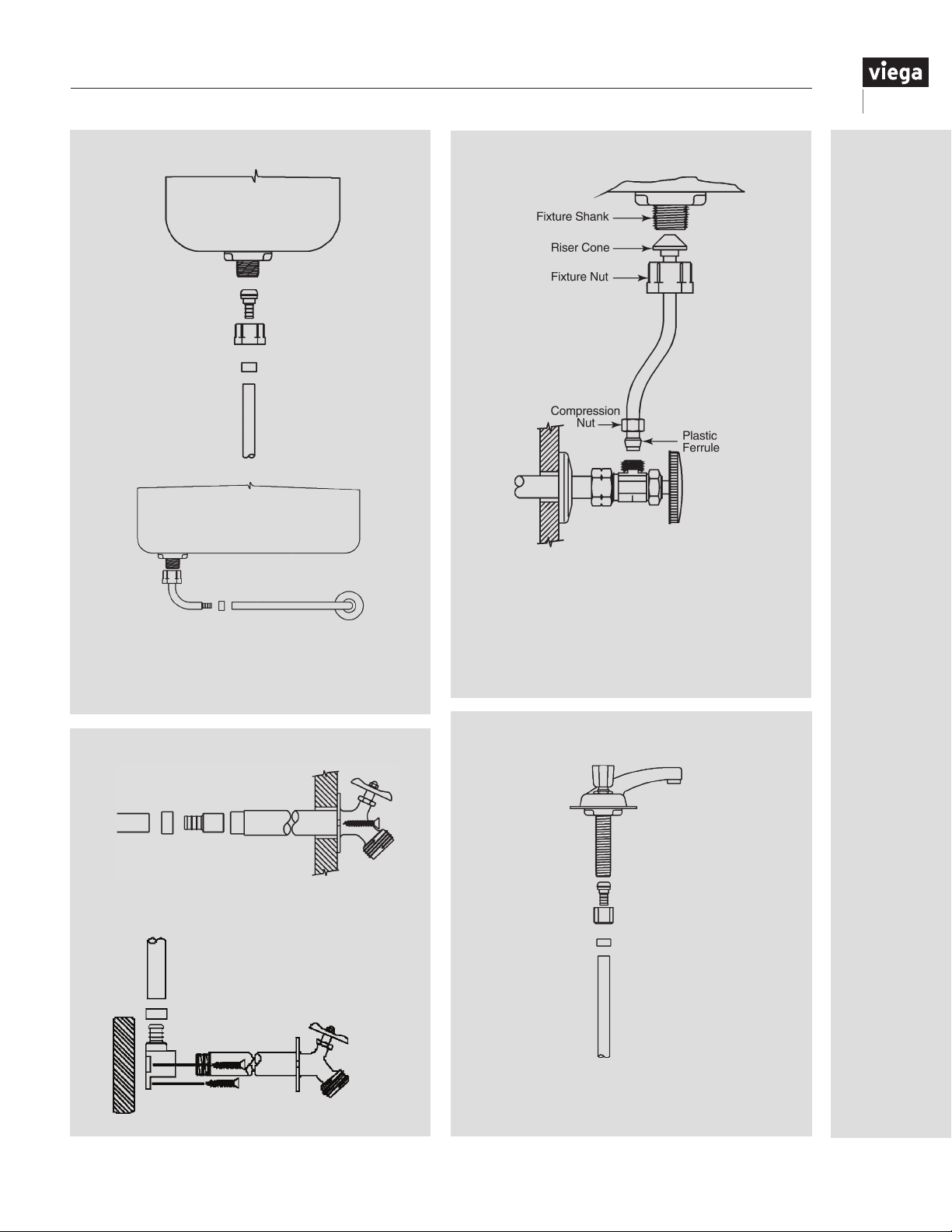
Viega Water Closet Connections
Tighten xture nut hand-tight plus an additional
¼-turn. Check all connections for leaks.
DO NOT OVERTIGHTEN.
Viega Riser Connections
Thread xture nut onto xture shank. Tighten
xture nut hand-tight plus an additional ½-turn.
Slide compression nut and supplied plastic
ferrule over tube as shown. The long taper
of the ferrule goes toward the valve. Tighten
compression nut according to valve manufacturer’s
recommendations.
Viega Wall Hydrant Connections
Hose bibbs supported by the structure
can be connected directly.
IM-PF 724596 0416
Lav Or Kitchen Faucet Connections
Freestanding hose bibbs shall
not be supported by ViegaPEX
Ultra. Well-anchored drop-ear
ttings or metal pipe shall be
used to install hose bibbs.
Tighten xture nut hand-tight plus an additional
¼-turn. Check all connections for leaks.
DO NOT OVERTIGHTEN.
59
Page 60
18 Pressure Testing Viega PEX Systems
18.1 General
Upon the completion of installing a Viega PEX
plumbing system, a hydrostatic (potable water)
pressure test shall be conducted. If potable water
is not available, or the potential for a freezing
condition exists, pneumatic* (air or nitrogen) testing
and/or the use of an RV antifreeze** solution are
also acceptable methods for pressure testing.
* Use air testing only if approved by local code or
the Authority Having Jurisdiction (AHJ)!
** RV antifreeze shall be drained and ushed from
all portions of the plumbing system prior to
consumer use.
Always refer to local plumbing code for pressure
testing requirements and approved methods
specic to plastic plumbing systems. If none
is specied, refer to Table 18.1 for acceptable
methods, test pressures and durations.
NOTICE - ManaBloc VALVE INFORMATION!
Opening a port valve to an empty or
unpressurized distribution line may cause
valve damage.
To prevent potential valve damage or failure, open the
port valves before filling and pressurizing the lines. The
force of water rushing to fill an empty line can cause
the valve’s seal to “clip off,” resulting in incomplete
sealing or complete valve failure.
CARE must be exercised when opening a port valve to
an empty or unpressurized line. The fixture to which the
line is connected should be in the OFF position and the
valve must be opened slowly until water starts to flow
into the line.
DO NOT CONTINUE to open the valve until the line is
full and pressurized. Open the valve fully only after the
line is up to system pressure. The fixture can then be
opened to purge the line of air.
Valve stems are replaceable. Order part number 51602.
WATER TESTING SHALL BE AVOIDED
DURING FREEZING CONDITIONS. UNDER NO
CIRCUMSTANCES SHALL THE SYSTEM BE
TESTED AT TEMPERATURES LOWER THAN
10˚F (-12˚C).
FOLLOW ANTIFREEZE MANUFACTURER’S
INSTRUCTIONS FOR CONCENTRATIONS.
Use only nontoxic antifreeze approved for
drinking water systems.
NOTE: If such a solution is used, the antifreeze solution
must be sufciently concentrated to withstand the
lowest temperature encountered while the testing uid
is in the system. Antifreeze solutions should be purged
and the system ushed with potable water prior to
consumer use.
WARNING! PRESSURES USED IN
TESTING CAN BLOW UNMADE OR
INCOMPLETE CONNECTIONS APART
WITH TREMENDOUS FORCE!
This force is many times greater when air is used as
a test medium. To reduce the risk of personal injury,
ensure that all connections are completed before
testing. Use only the pressure and time required to
determine that the system is leak free.
Testing Viega PEX Systems (Branch and Main / ManaBloc)
Test Method Min/Max Duration (Min) Max Pressure (psi) Min Pressure (psi) Allowable Variance (psi)
Water 15 min/1 hr 100 40 N/A
Air 15 min/1 hr 100 40 8*
Table 18.1
* If the pressure in the system declines more than 8 psi during the 15-minute to one-hour period, repressurize the system to the
original test pressure and retest. If the system pressure declines more than 8 psi again during the test period, test the distribution line
test caps or any other ttings in the system with the approved leak-detect solution.
NOTE: Some plumbing xtures may not withstand test pressures greater than 80 psi. Consult xture manufacturer’s instructions for pressure
limitations or plug all distribution lines at the xture end. The system shall, at a minimum, withstand the test pressure, without leaking, for a
period of 15 minutes.
60
IM-PF 724596 0416
Page 61
18.2 Air testing
Air testing of a Viega PEX plumbing system shall
use the checklist provided to ensure safety.
It is the responsibility of the installer to
read and understand the below pressure
testing criteria and all safety precautions.
Compressed air can store extremely high
energy as compared to compressed water
systems. Failure to follow these steps could result
in personal injury, death and/or property damage.
Preparing for air pressure test:
Notify other trades that air pressure test will
be conducted on the plumbing system. Only
qualied personnel should be present during the
system testing.
Use only compressed air or nitrogen that is free
of any kind of lubricating oils.
Do not conduct pressure testing overnight or if a
large temperature change is anticipated.
Before pressurizing the system, conduct a visual
inspection to ensure proper connections have
been made throughout the plumbing system.
All personnel involved in the pressure testing
shall wear, at a minimum, eye and hearing
protection. It is recommended the person
applying the pressure to the system wear a full
face shield.
Only Viega PEX plumbing system components
(tubing/ttings/manifolds) shall be pressure
tested. All other system components (water
heaters and xtures) shall be isolated from the
pressure test.
Contact the inspector and schedule the pressure test.
Pressurizing the system:
Verify no other trades are present prior to
starting the pressure test. Only qualied testing
personnel should be present during pressure test.
Introduce pressure into the system as outlined in
the stages below.
Stage 1: Gradually increase system pressure to 10
psi (approx. 30-sec. duration).
• Wait for 10 minutes before inspecting
pressure gauge.
• If pressure holds steady, continue to Stage 2.
• If pressure falls over the test period, look for
potential leaks with an approved leak-detect
solution. Once system pressure is completely
relieved and the leak is xed, restart test
procedure.
Stage 2: Gradually increase system pressure to 50
psi (approx. 1-min. duration).
• Wait for 10 minutes before inspecting
pressure gauge.
• If pressure holds stable, continue to Stage 3.
• If pressure falls over the test period, look for
potential leaks with an approved leak-detect
solution. Once system pressure is completely
relieved and the leak is xed, restart testing
procedure from beginning.
Stage 3: Gradually increase system pressure to
100 psi (approx. 1-min. duration).
• Inspect gauge pressure over next 10-minute
period to verify pressure has not decreased
more than the allowable variance noted in
Table 18.1.
• If pressure variance allowed is not exceeded,
the system test has passed.
• If pressure decreases more than the
allowable variance, the test has failed.
Apply approved leak-detect solution (see
“18.3 Leak detection” below) on tting
and/or manifold connections to isolate the
location of the leak. Once system pressure is
completely relieved and the leak is xed, start
testing procedure from beginning.
Completing the air test:
Depressurize system.
• Use of the same safety equipment applies to
these steps.
• Slowly bleed off any remaining air pressure
from system (approx. 1-min. duration).
• Notify other trades the test is complete and
work area is safe to occupy.
• Document the time and date test was
completed and the pressure and duration of
the test.
18.3 Leak detection
Viega has identied the leak detect solutions listed
below as being compatible for use with Viega PEX
Press system components. Consult leak detect
manufacturer for proper application and product
instructions. To determine the compatibility of other
leak detect solutions not listed below, contact
Viega Technical Services prior to their use.
• megabubble® Leak Detector
• Oatey® All Purpose Leak Detector
• Snoop Liquid Leak Detector
As an alternative leak detect, a mixture of Original
Palmolive Green™ dishwashing soap (#46100-
46200) or Palmolive Ultra™ (#356140 or 46128)
mixed with potable water at a ratio of two ounces
of soap to one gallon of water (mix Ultra at a ratio
of 1.5 ounces per gallon) may be used.
NOTE: If the solution does not show a leak on
any of the caps or ttings, isolate the ManaBloc
by turning the valves to the “OFF” position,
repressurize if needed and apply the same solution
to the ManaBloc manifold components.
IM-PF 724596 0416
61
Page 62
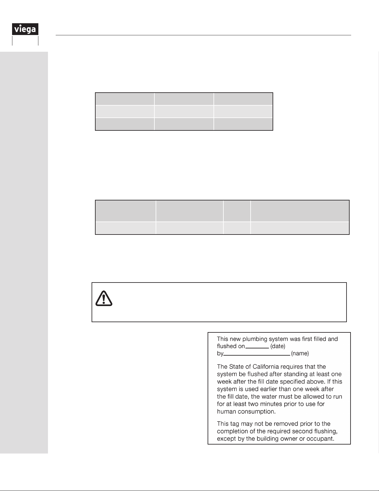
19 System Disinfection
19.1 General
Local codes may require system disinfection. When no other method is available, follow the time limitations and
exposure levels shown below.
1. Use a chlorine solution and one of the exposure durations listed below:
Concentration Period Authority
200 PPM 3 hours IPC/UPC
50 PPM 24 hours IPC/UPC
®
®
2. Mix the disinfection solution thoroughly before adding it to the system.
3. The chlorine solution must reach all parts of the system. Open all xtures (both sides) and ow water
until a chlorine smell is present. As an alternative, chlorine test tablets can be used to detect chlorine
at each xture.
4. The chlorine source for the solution can be, but is not limited to, the following:
Chlorine Source % Active Chlorine Form
Amount Per 100 Gallons Water
for a 200 PPM Solution
Laundry bleach 5.25 Liquid 3 pints (48 oz.)
5. After the solution has been in the system for the time required by the Authority Having Jurisdiction
(AHJ) or the exposure durations listed in Step 1, the system shall be ushed completely with
potable water.
6. The system must be purged or drained of all water or protected from freezing.
FAILURE TO FLUSH THE SYSTEM NOTICE!
To prevent reduced service life of system components, disinfection solutions
shall not be allowed to stand in the system longer than 24 hours. Thoroughly
ush the system with potable water after disinfection.
19.2 California flushing requirements
The State of California requires all installations of
PEX piping, where it is the initial plumbing system
installed in new construction, shall be ushed twice
over a period of at least one week. The piping
system shall be rst ushed for at least 10 minutes
and then lled and allowed to stand for no less
than one week, after which all the branches of the
piping system must be ushed long enough to fully
empty the contained volume. This shall not apply
to installations of PEX pipe where it replaces an
existing tubing system of any material.
At the time of ll, each xture shall have a
removable tag, shown on the right.
62
IM-PF 724596 0416
Page 63

20 Warranty
VIEGA® LLC PEX WATER SYSTEMS LIMITED WARRANTY
Subject to the conditions and limitations in this Limited Warranty, VIEGA LLC (Viega) warrants to the owner of applicable real property
in the United States (including its territories) and Canada that the components in its PEX Plumbing Systems (as described below) when
properly installed by licensed plumbers in potable water systems, under normal conditions of use, shall be free from failure caused by
manufacturing defects for a period of twenty-ve (25) years from date of installation.
Viega PEX Plumbing Systems and components covered by this twenty-ve (25) year warranty are:
ViegaPEX™ and ViegaPEX™ Ultra cross-linked polyethylene (PEX) tubing or FostaPEX® tubing installed with PEX metal or
polymer press ttings and PEX Press sleeves sold by Viega installed as a system.
ViegaPEX and ViegaPEX Ultra cross-linked polyethylene (PEX) tubing and ASTM F1807 metal crimp insert ttings sold by Viega
and ASTM F2159 PolyAlloy™ crimp ttings sold by Viega installed with copper crimp rings as a system.
Viega warrants that ManaBloc®, MiniBloc™ or polymer or metallic manifolds, and their approved connections, sold by Viega and
installed as a manifold plumbing system under normal conditions of use, shall be free from failure caused by manufacturing defects for
a period of ten (10) years from date of installation.
Power tools and jaws used with PEX Press ttings are warranted by the manufacturer and Viega extends no separate warranty on
those tools or jaws. Viega warrants that PEX Press hand tools sold by Viega, under normal conditions of use, shall be free from failure
caused by manufacturing defects for a period of two (2) years from date of sale. Viega warrants that PEX Crimp hand tools and tubing
cutters sold by Viega, under normal conditions of use, shall be free from failure caused by manufacturing defects for a period of twelve
(12) months from date of sale.
Viega warrants that properly installed PEX valves, PEX lav and closet risers and riser accessories manufactured and/or sold by Viega
shall be free from failure caused by manufacturing defects for a period of two (2) years from date of installation.
Viega does not extend any warranty on its components used in systems with tubing, ttings, manifolds, or press sleeves not sold by
Viega or installed by other than a licensed plumber. In addition, the warranty does not apply if distribution lines and their connections
to manifold plumbing systems sold by Viega are not ViegaPEX, ViegaPEX Ultra or FostaPEX tubing or approved connections sold by
Viega.
Connection to non-Viega plumbing products intended for riser and/or water service applications does not void the systems warranty
provided all pipe, ttings, valves and manifolds are sold by Viega after the transition location.
Termination connections to non-Viega end-use devices or equipment such as ltration, water softeners, shower valves, faucets, stops
and other such devices, when utilizing ViegaPEX, ViegaPEX Ultra and FostaPEX does not void the system warranty as described.
Under this limited warranty, you only have a right to reimbursement if the failure or leak or resulting damage resulted from a
manufacturing defect in the products covered by this warranty and the failure or leak or resulting damage occurred during the warranty
period. You do not have a remedy or right of reimbursement under this warranty and the warranty does not apply if the failure or leak
or resulting damage is caused by (1) components in the plumbing system other than those manufactured or sold by Viega; (2) not
designing, installing, inspecting, testing, or operating the system in accordance with Viega’s installation instructions at the time of the
installation, applicable code requirements and good plumbing practices; (3) improper handling and protection of the product prior
to and during installation, exposure to ultra violet light, inadequate freeze protection, exposure to water pressures or temperatures
in excess of the limitations on the tubing or application of unauthorized or harmful solvents or chemicals; (4) chemically corrosive or
aggressive water conditions; or (5) acts of nature such as earthquakes, re, ood or lightning.
In the event of a failure or leak in the system, it is the responsibility of the property owner to obtain and pay for repairs. Only if the
warranty applies will Viega be responsible for reimbursement under this warranty. The part or parts which you claim failed should
be kept and Viega contacted at the address below or by telephoning 800-976-9819 within thirty (30) days after the failure or leak
and identifying yourself as having a warranty claim. You should be prepared to ship, at your expense, the product which you claim
failed due to a manufacturing defect, document the date of installation, and the amount of any claimed bills for which you seek
reimbursement. Within a reasonable time after receiving the product, Viega will investigate the reasons for the failure, which includes
the right to inspect the product at Viega and reasonable access to the site of damage in order to determine whether the warranty
applies. Viega will notify you of the results of this review.
In the event that Viega determines that the failure or leak and any resulting damages were the result of a manufacturing defect in the
products covered by the 10-year or 25-year limited warranties and occurred during the rst ten (10) years covered by this warranty,
Viega will reimburse the property owner for reasonable repair or replacement charges to include drywall, ooring and painting costs,
as well as damages to personal property, resulting from the failure or leak. The remaining 15-year limited warranty for products
covered by the 25-year limited warranty will cover material costs for pipe and ttings only, sold by Viega, not inclusive of any labor or
installation costs. Any change in property ownership after the rst ten years will nullify any remaining warranty coverage.
VIEGA SHALL NOT BE LIABLE FOR CONSEQUENTIAL ECONOMIC LOSS DAMAGES UNDER ANY LEGAL THEORY AND WHETHER
ASSERTED BY DIRECT ACTION, FOR CONTRIBUTION OR INDEMNITY OR OTHERWISE.
THE ABOVE LIMITED WARRANTY IS IN LIEU OF ALL OTHER WARRANTIES, EXPRESS OR IMPLIED, INCLUDING BUT NOT LIMITED
TO, THE IMPLIED WARRANTIES OF MERCHANTABILITY AND FITNESS FOR A PARTICULAR PURPOSE. IF FOUND APPLICABLE,
ANY IMPLIED WARRANTIES ARE LIMITED TO THE DURATION OF THE TIME LIMITS SET OUT IN THIS WRITTEN WARRANTY. Other
than this limited warranty, Viega does not authorize any person or rm to create for it any other obligation or liability in connection with
its products. This written warranty applies for the rst 10 years of the applicable warranty regardless of any change of ownership in the
property.
Some states do not allow the exclusion or limitation of incidental or consequential damages or limitations on the duration of implied
warranties in certain types of transactions, so the above exclusion or limitations may not apply to you. This limited warranty gives you
specic legal rights and you also may have other rights which vary from state to state. This warranty shall be interpreted and applied
under the law of the state in which the product is installed.
Effective 02/01/2016
IM-PF 724596 0416
63
Page 64

Viega LLC
100 N. Broadway, 6th Floor
Wichita, KS 67202
Phone: 1-800-976-9819
Fax: 1-316-425-7618
www.viega.us
This document subject to updates. For the most current Viega technical literature please visit www.viega.us.
Click Services -> Click Electronic Literature Downloads -> Select Product Line -> Select Desired Document
*Zero Lead identies Viega
NSF/ANSI 372 (0.25% or less maximum weighted average lead content).
©2016, Viega®, ProPress®, MegaPress®, XL®, XL-C®, SeaPress®, Smart Connect®,
SmartLoop®, PureFlow®, ManaBloc®, GeoFusion®, FostaPEX®, Radiant Wizard®,
S-NO-ICE®, Climate Panel®, Snap Panel®, Climate Mat®, and Climate Track® are
registered trademarks of Viega GmbH & Co. KG. ViegaPEX™ is a trademark of Viega
GmbH & Co. KG. MiniBloc™, ProRadiant™, Zero Lead™ and PolyAlloy™ are trademarks
of Viega LLC. Eco Brass® is a registered trademark of Mitsubishi Shindoh Co., LTD.
RIDGID® is a registered trademark of RIDGID, Inc. LoopCAD® is a registered trademark of
Avenir Software Inc. Radel® is a registered trademark of Solvay Advanced Polymers, LLC.
®
products meeting the lead free requirements of NSF 61-G through testing under
IM-PF 724596 0416
 Loading...