

Page 1

Vision Model 20
Vision Model 20ET
Owner's Manual
®
Page 2

Table of Contents
Table of Contents
Table of Contents .......................................................................................................... 1
Warning .......................................................................................................................... 4
Two Year Limited Warranty ....................................................................................... 6
Overview ........................................................................................................................ 8
Features ...................................................................................................................................... 8
Projector Exterior View ......................................................................................................... 10
Front / Upper Side ........................................................................................................................................ 10
Rear / Bottom Side ....................................................................................................................................... 11
Controls and Functions .......................................................................................................... 12
Control Panel ................................................................................................................................................ 12
Connector Panel ........................................................................................................................................... 14
Remote Control
Installation ................................................................................................................... 17
Remote Control ...................................................................................................................... 17
Projector .................................................................................................................................. 18
Connect the Power Cord ............................................................................................................................... 18
Adjust the Lens Zoom/Focus ring ................................................................................................................ 18
Adjust the height ........................................................................................................................................... 19
Installation For Vision Model 20 (With 1.71 - 2.06 Lens) ................................................... 20
Throw Distance Chart For Vision Model 20 (With 1.71 - 2.06 Lens) ................................ 21
............................................................................................................ 15
English
1
Page 3

Vidikron Owner’s Manual
English
Installation For Vision Model 20ET (With 2.31 - 3.06 Lens) .............................................. 22
Throw Distance Chart For Vision Model 20ET (With 2.31 - 3.06 Lens) ........................... 23
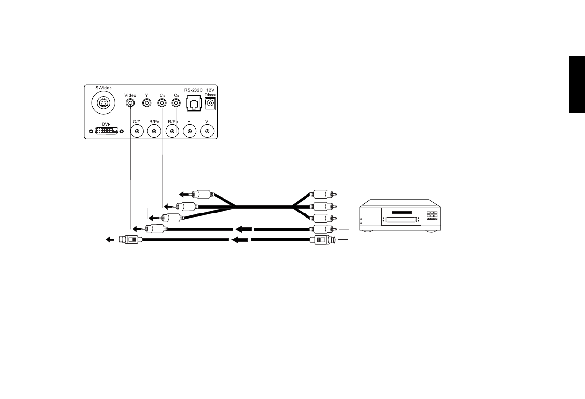
Connecting ................................................................................................................... 24
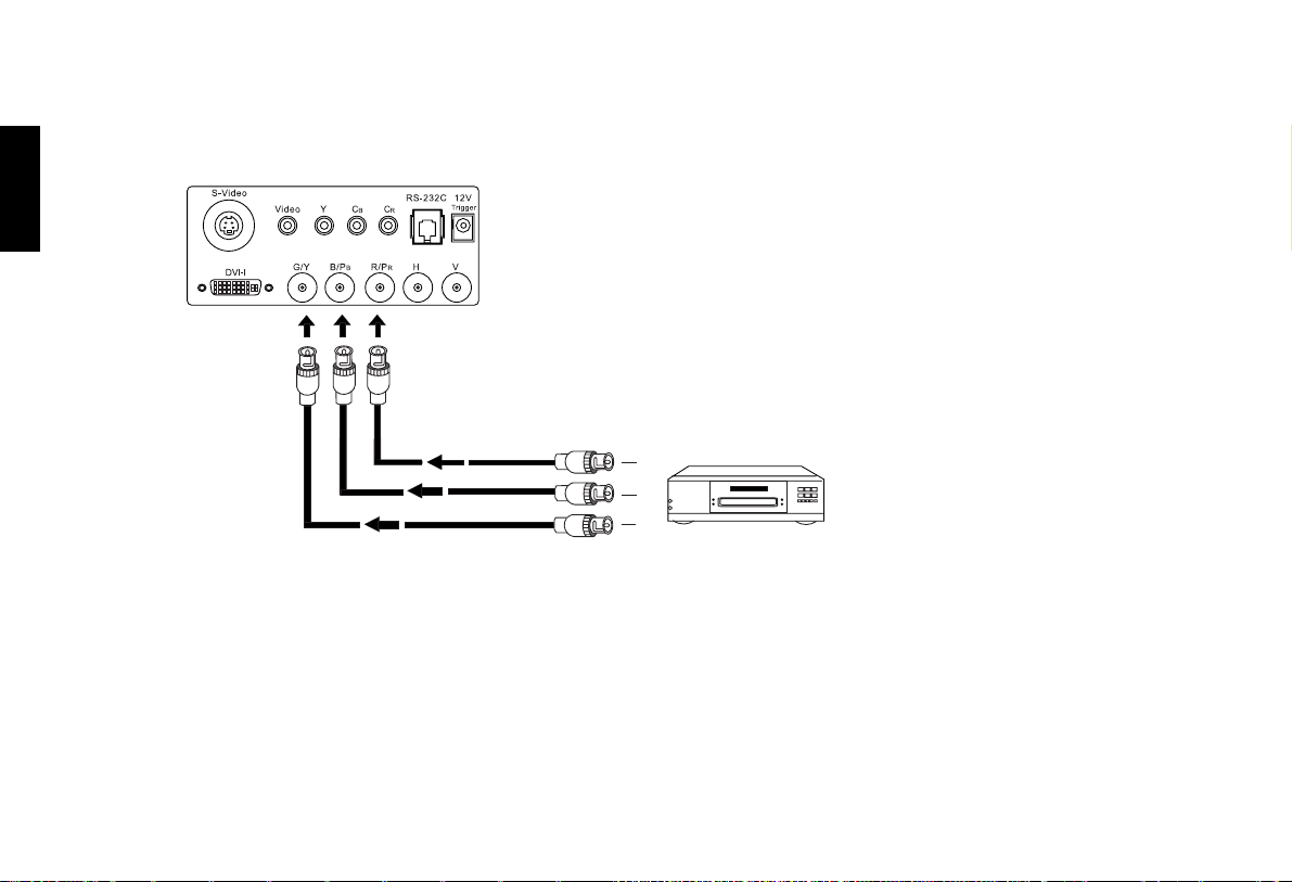
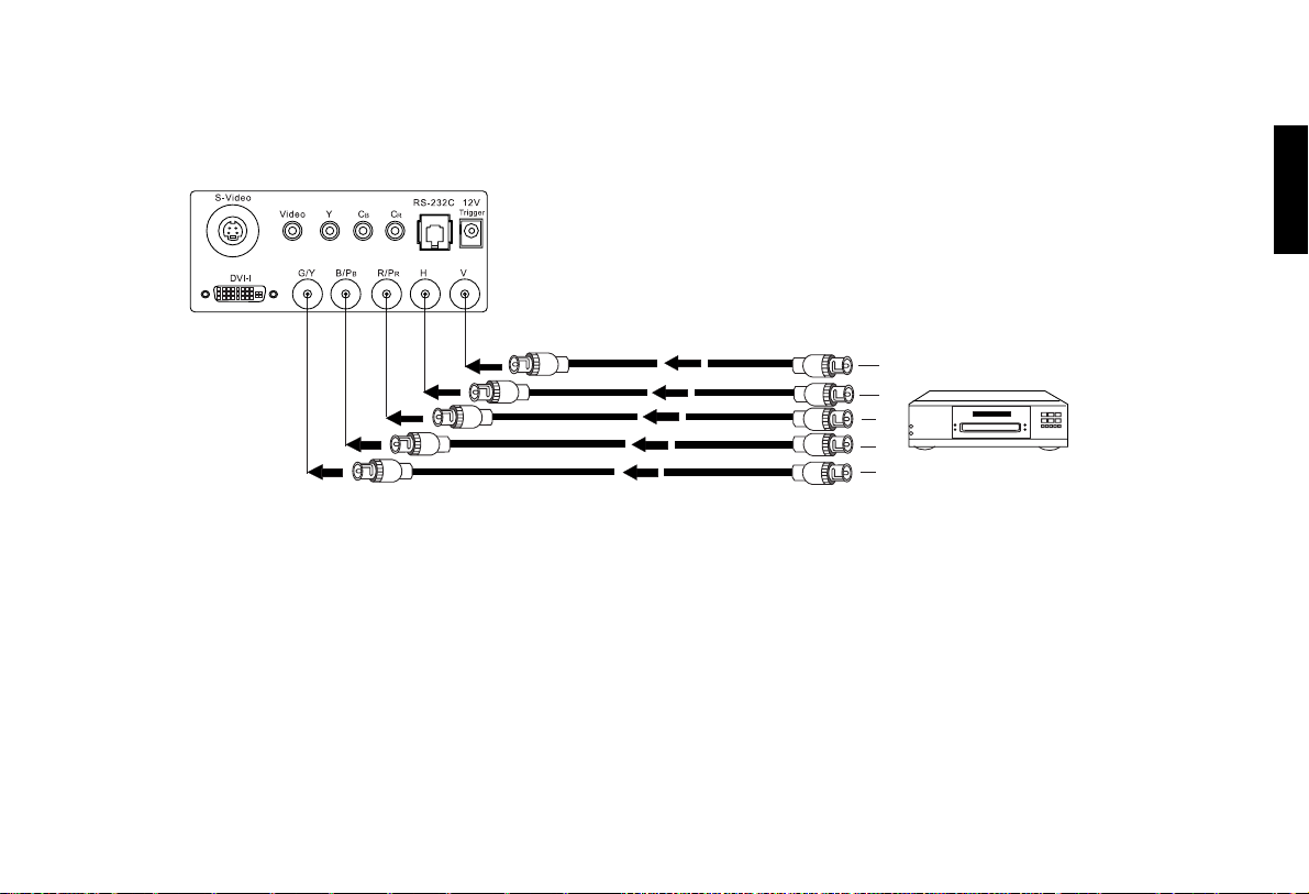
Connecting Video Inputs ........................................................................................................ 25
Video / S-Video / Component (Interlaced Video) ....................................................................................... 25
Progressive Component (DTV Y/PB/PR) .................................................................................................. 26
RGBHV (DTV RGB) ................................................................................................................................... 27
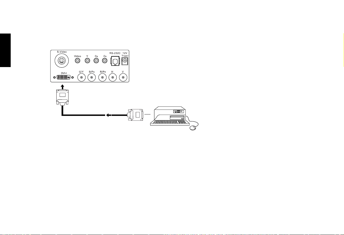
Connecting a Computer or HDCP Compatible Video Device With DVI-I Output .......... 28
Basic Operation ........................................................................................................... 29
Turning on the Power ............................................................................................................. 29
Zoom/ Focusing ....................................................................................................................... 30
Selecting Video Memory ........................................................................................................ 30
Selecting Input Source ............................................................................................................ 31
Setting Menu ........................................................................................................................... 31
Selecting "ASPECT RATIO" ................................................................................................ 32
PIP/ POP function ................................................................................................................... 32
Turning off the Power ............................................................................................................ 33
Menu ............................................................................................................................. 34
Using the Menu ....................................................................................................................... 34
Main Menu .............................................................................................................................. 35
Picture Quality Adjustments ................................................................................................. 35
2
Page 4

Table of Contents
Image Options 1 ...................................................................................................................... 36
Input Select ................................................................................................................................................... 36
Aspect Ratio ................................................................................................................................................. 37
Image Option 2 ........................................................................................................................ 38
Projector Status ....................................................................................................................... 39
Install ........................................................................................................................................ 40
Service ...................................................................................................................................... 41
White Balance ............................................................................................................................................... 41
Blue Enable ................................................................................................................................................... 42
Reset Lamp Timer ........................................................................................................................................ 42
Additional Information ............................................................................................... 43
Replace the Lamp (Contact your Vidikron Dealer) ............................................................ 43
Troubleshooting ...................................................................................................................... 44
Specifications ........................................................................................................................... 46
Dimensions ............................................................................................................................... 48
RS-232 Setup ........................................................................................................................... 49
RS-232C Control Codes ............................................................................................................................... 49
PC Out Adapter ............................................................................................................................................ 50
English
3
Page 5
English
Vidikron Owner’s Manual
Vidikron Vision Model 20/ Vision Model 20ET Owner’s Manual
Thank you for your purchase of this quality Vidikron video projector. It has been designed to provide you with the quality of video that is
expected in a high performance home theater. For the best results, please read this manual carefully as it is your guide through the menus
and operation.
Warning
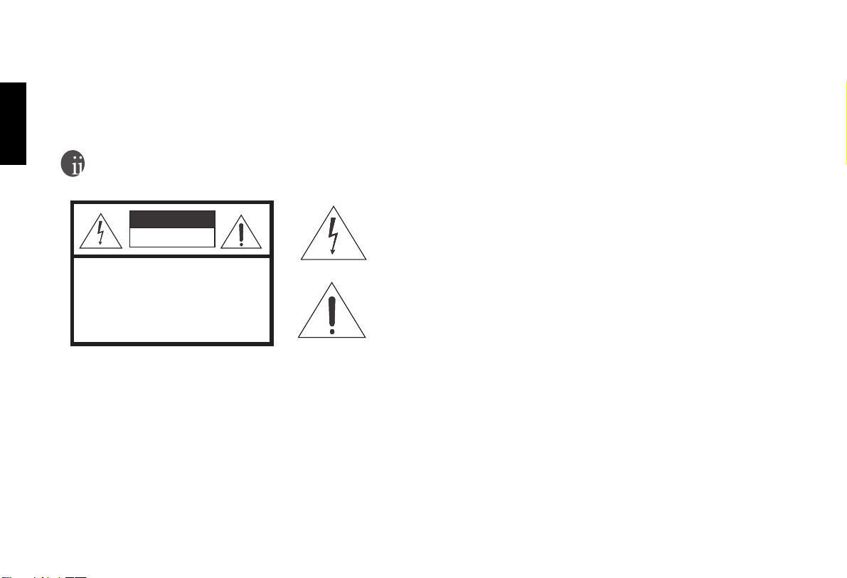
This symbol is intended to alert the user to the presence of uninsulated
CAUTION
RISK OFELECTRIC SHOCK
DO NOTOPEN
" dangerous voltage " within the product's enclosure that may be of sufficient magnitude to constitute a risk of electric shock.
CAUTION: TOREDUCE THE RISKOF ELECTRIC SHOCK.
DO NOTREMOVE COVER (ORBACK)
NO USERSERVICEABLE PARTSINSIDE.
REFER SERVICINGTO QUALIFIED SERVICEPERSONNEL.
This equipment has been tested and found to comply with the limits for a Class B digital device, pursuant to Part 15 of the FCC Rules. These
limits are designed to provide reasonable protection against harmful interference in a residential installation.
1. Read these instructions.
2. Keep these instructions.
3. Heed all warnings.
4. Do not use this projector near water, outdoors or otherwise exposed to the elements.
5. Clean only with a dry cloth.
4
This symbol is intended to alert the user to the presence of important
operating and maintenance (servicing) instructions in the literature
accompanying the appliance.
Page 6

Warning
6. Do not block any ventilation openings.
7. Do not install near any heat sources such as radiators, heat registers, stoves, or other apparatus (including amplifiers) that produce
heat.
8. Do not defeat the safety feature of the polarized or grounding type plug. A polarized type plug has two blades with one wider than the
other. A grounding type plug has two blades and a third grounding prong. The third prong is provided for your safety. If the provided
plug does not fit into your outlet, consult an electrician for the replacement of the obsolete outlet.
9. Do not connect the RJ-11, RS-232 jack to a telephone line connection.
10. The 12V trigger outputs 12V DC for triggering. Do not connect to any other power input or output. This could cause damage to this
unit.
11. Only use accessories specified by Vidikron.
12. Keep the packing material in case the projector should ever need to be shipped.
13. Unplug this projector during lightning storms or when it will not be used for an extended period of time.
14. The lamp becomes extremely hot during operation. Allow the projector to cool down for approximately 45 minutes prior to removing
the lamp assembly for replacement. Do not operate lamps beyond the rated lamp life. Excessive operation of lamps beyond rated life
could cause them to explode in rare occasions.
Refer all servicing to qualified service personnel. Servicing is required when the projector has been damaged in any way, objects have fallen
or spilled into the projector, the projector has been exposed to rain or moisture, does not operate normally, or has been dropped.
English
5
Page 7

Vidikron Owner’s Manual
English
Two Year Limited Warranty
Congratulations on your purchase of a Vidikron video product and welcome to the Vidikron family! With proper installation, setup and care,
you should enjoy many years of unparalleled video performance.
This is a LIMITEDWARRANTY as defined in the Magnuson-Moss Warranty Act. Please read it carefully and retain it with your other
important documents.
WHAT IS COVERED UNDER THE TERMS OF THIS LIMITED WARRANTY:
SERVICE LABOR: Vidikron will pay for service labor by a Vidikron Authorized Service Center when needed as a result of
manufacturing defect for a period of two (2) years from the effective date of delivery to the end user (excluding the lamp).
PAR TS: (Not including the lamp) Vidikron will provide new or rebuilt replacement parts for the parts that fail due to defects in materials or
workmanship for a period of two (2) years from the effective date of delivery to the end user. Such replacement parts are then subsequently
warranted for the remaining portion (if any) of the original warranty period.
PROJECTOR LAMP: Vidikron will pay for service labor by a Vidikron Authorized Service Center when needed as a result of a
manufacturing defect for a period of six (6) months or 1000 hours, whichever comes first, from the effective date of delivery to the end user.
In addition, Vidikron will provide a new or rebuilt replacement lamp for the lamp that fails due to defects in materials or workmanship for a
period of six (6) months or 1000 hours, whichever comes first, from the effective date of delivery to the end user. Such replacement lamps are
then subsequently warranted for the remaining portion (if any) of the original warranty period.
WHAT IS NOT COVERED UNDER THE TERMS OF THIS LIMITED WARRANTY:
This Limited Warranty only covers failure due to defects in materials and workmanship that occur during normal use and does not cover
normal maintenance. This Limited Warranty does not cover cabinets or any appearance items; failure resulting from accident, misuse, abuse,
neglect, mishandling, misapplication, faulty or improper installation or setup adjustments; improper maintenance, alteration, improper use
of any input signal; damage due to lightning or power line surges, spikes and brownouts; damage that occurs during shipping or transit; or
damage that is attributed to acts of God. In the case of remote control units, damage resulting from leaking, old, damaged or improper
batteries is also excluded from coverage under this Limited Warranty.
CAUTION: THIS LIMITED WARRANTY ONLY COVERS VIDIKRON PRODUCTS PURCHASED FROM VIDIKRON
AUTHORIZED DEALERS. ALL OTHER PRODUCTS ARE SPECIFICALLY EXCLUDED FROM COVERAGE UNDER THIS
LIMITED WARRANTY. MOREOVER, DAMAGE RESULTING DIRECTLY OR INDIRECTLY FROM IMPROPER INSTALLATION
OR SETUP IS SPECIFICALLY EXCLUDED FROM COVERAGE UNDER THIS LIMITED WARRANTY.
6
Page 8

Two Year Limited Warranty
RIGHTS, LIMITS AND EXCLUSIONS:
Vidikron limits its obligations under any implied warranties under state laws to a period not to exceed the warranty period. There are no
express warranties. Vidikron also excludes any obligation on its part for incidental or consequential damages related to the failure of this
product to function properly. Some states do not allow limitations on how long an implied warranty lasts, and some states do not allow the
exclusion or limitation of incidental or consequential damages. So the above limitations or exclusions may not apply to you. This warranty
gives you specific legal rights, and you may also have other rights that vary from state to state.
EFFECTIVE WARRANTY DATE:
This warranty begins on the effective date of delivery to the end user. For your convenience, keep the original bill of sale as evidence of the
purchase date.
IMPORTANT: WARRANTY REGISTRATION:
Please fill out and mail your warranty registration card. It is imperative that Vidikron knows how to reach you promptly if we should
discover a safety problem or product update for which you must be notified.
CONTACT A VIDIKRON AUTHORIZED SERVICE CENTER TO OBTAIN SERVICE
Repairs made under the terms of this Limited Warranty covering your Vidikron video product will be performed at the location of the product, during usual working hours, providing location of product is within normal operating distance from a Vidikron Authorized Service Center. In some instances it may be necessary for the product to be returned to the Vidikron factory for repairs. If, solely in Vidikron's judgment,
location of product to be repaired is beyond normal operating distance of the closest Vidikron Authorized Service Center, or the repair
requires the unit be returned to the Vidikron factory, it is the owner's responsibility to arrange for shipment of the product for repair. These
arrangements must be made through the selling Vidikron dealer. If this is not possible, contact Vidikron directly to locate an authorized Vidikron representative who will assist you in getting a return authorization. Vidikron will return product transportation prepaid in the United
States, unless no product defect is discovered. In that instance, shipping costs will be the responsibility of the owner.
ADDITIONAL INFORMATION:
To locate the name and address of the nearest VIDIKRON authorized service location, or for additional information about this warranty,
please call or write:
VIDIKRON
Attn: Customer Service Department
2900 Faber Street
Union City, CA 94587
Ph: (510) 324-5900
Fax: (510) 324-5905
7
English
Page 9

Vidikron Owner’s Manual
English
Overview
Features
■ 1024 x 576 Native 16:9 Resolution Single DMD
■ Integrated Video Processing With 3:2 Pulldown
■ 850 ANSI Lumens/ 1500:1 Contrast Ratio
■ Multiple Aspect Ratios with Intelliwide Mode
■ HDTV Ready
480P, 1080i and 720P (576P PAL Version) formats are all compatible with this unit (via an external DTV decoder, not provided).
■ DVI-I Input with HDCP
■ 9-Point White Balance System for Excellent Gray Scale Tracking
■ Direct IR and RS-232 Control
■ ‘Cat’s Eye’ Optical System for Enchanced Contrast and Black Levels
■ Two Lens Options with Variable Throw Distances for Versatile Installation Convenience
■ De-interlacing with 3:2 Pull-down
Using Vidikron’s proprietary de-interlacing technology, this projector provides exceptional scaling and film to video (3:2 pulldown) conversion for the most artifact-free images possible.
TM
Chip Display Device
8
Page 10

■ PIP/ PBP function
Picture in picture/ Picture by picture functions allow you to display two inputs on the screen at the same time.
■ Video Memory
This projector allows the user to store up to three different settings per input.
Overview
English
9
Page 11
English
Vidikron Owner’s Manual
Projector Exterior View
Front / Upper Side
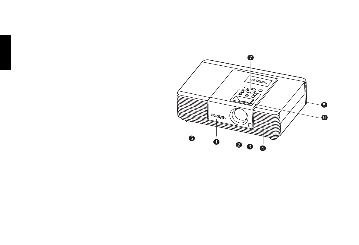
1. Front Lamp Cover
Remove this cover when replacing the lamp. (See page 43.)
2. Projection Lens
3. Front IR Sensor
4. Ventilation Holes (intake)
5. Ventilation Holes (exhaust)
6. Focus Ring and Zoom Ring Access
Adjusts the focus and zoom of image.
7. Control Panel
Shows lamp status and whether the projector is on or off.
For more details, see "Control Panel" on page 12.
8. Kensington Lock
This lock can withstand 150 N of force.
10
Page 12
Rear / Bottom Side
Overview
English
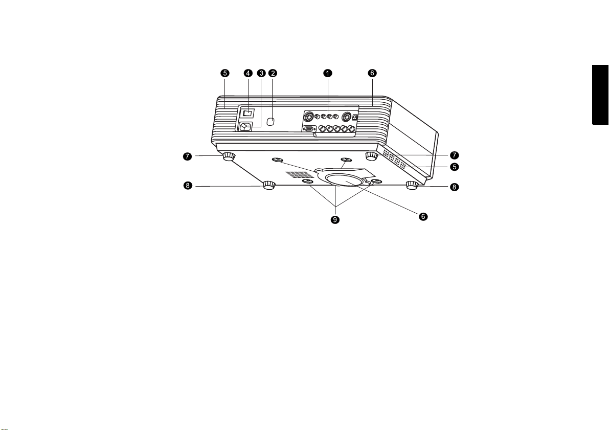
1. Connector Panel
For more details, see "Connector Panel" on page 14.
2. Back IR Sensor
3. AC Power IN Socket
4. AC Power Switch
AC main power switch.
5. Ventilation Holes (exhaust)
6. Ventilation Holes (intake)
7. Rear Adjusters
Adjusts the height or projection angle.
8. Front Adjusters
Adjusts the height or projection angle.
9. Ceiling Mount Holes
The connecting holes for ceiling mount device.
11
Page 13
English
Vidikron Owner’s Manual
Controls and Functions
Control Panel
12
Page 14

Overview
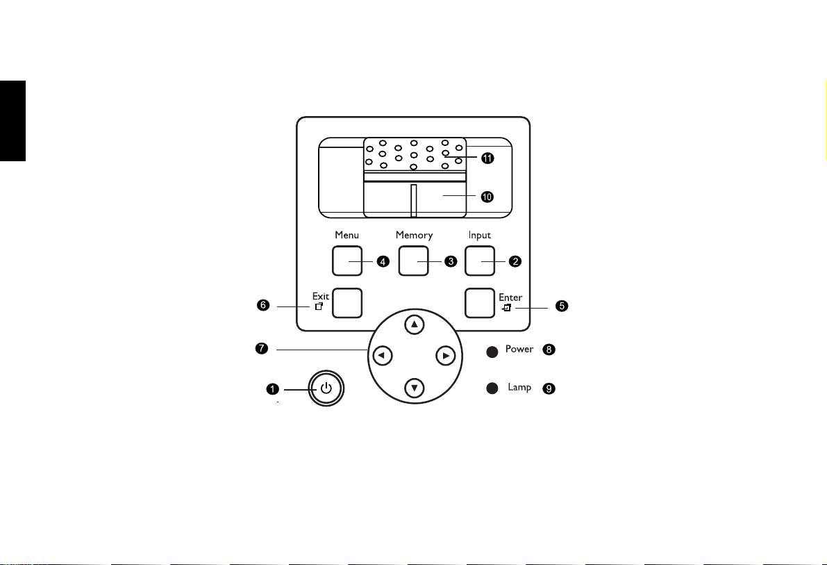
1. STANDBY/ON
Press this key for ONE second to turn on the unit when it is in the
standby mode. Or press this key to turn off this unit when it is on.
2. INPUT
Switches input sources sequentially.
3. MEMORY
Sequentially recalls settings 1 ~ 3 saved to memory. (Please see
"Selecting Video Memory" on page 30.)
4. MENU
Turns the on-screen display control menu on or off.
5. ENTER
Enters settings for items shown in the menu.
6. EXIT
Exits and saves the setting(s) of items in the menu.
7. ARROW (c/e/d/f)
Use to select the menu or to make various adjustments.
8. POWER LED
Indicates power status
■ Lit orange when the AC power cord is plugged into the wall outlet
(standby mode). Once in the standby mode, you can press the
STANDBY/ON key on the projector or the ON key on the remote
control for ONE second to turn on the projector.
■ Lit green when the power is turned on (operational mode).
■ Flashes orange for the first 30 seconds after powering up, indicating
that the lamp is warming up.
■ Flashes green for one minute after the projector is turned off to
indicate that the lamp is cooling down.
9. LAMP LED
Indicates the status of lamp.
■ Lit red when the lamp has developed a problem. Please contact your
Vidikron dealer for assistance.
10. Zoom Ring
Adjusts the size of image
■ Rotate clockwise to enlarge the image or rotate counterwise to make
the image smaller.
11. Focus Ring
Adjust the focus of the projected images.
English
13
Page 15
Vidikron Owner’s Manual
English
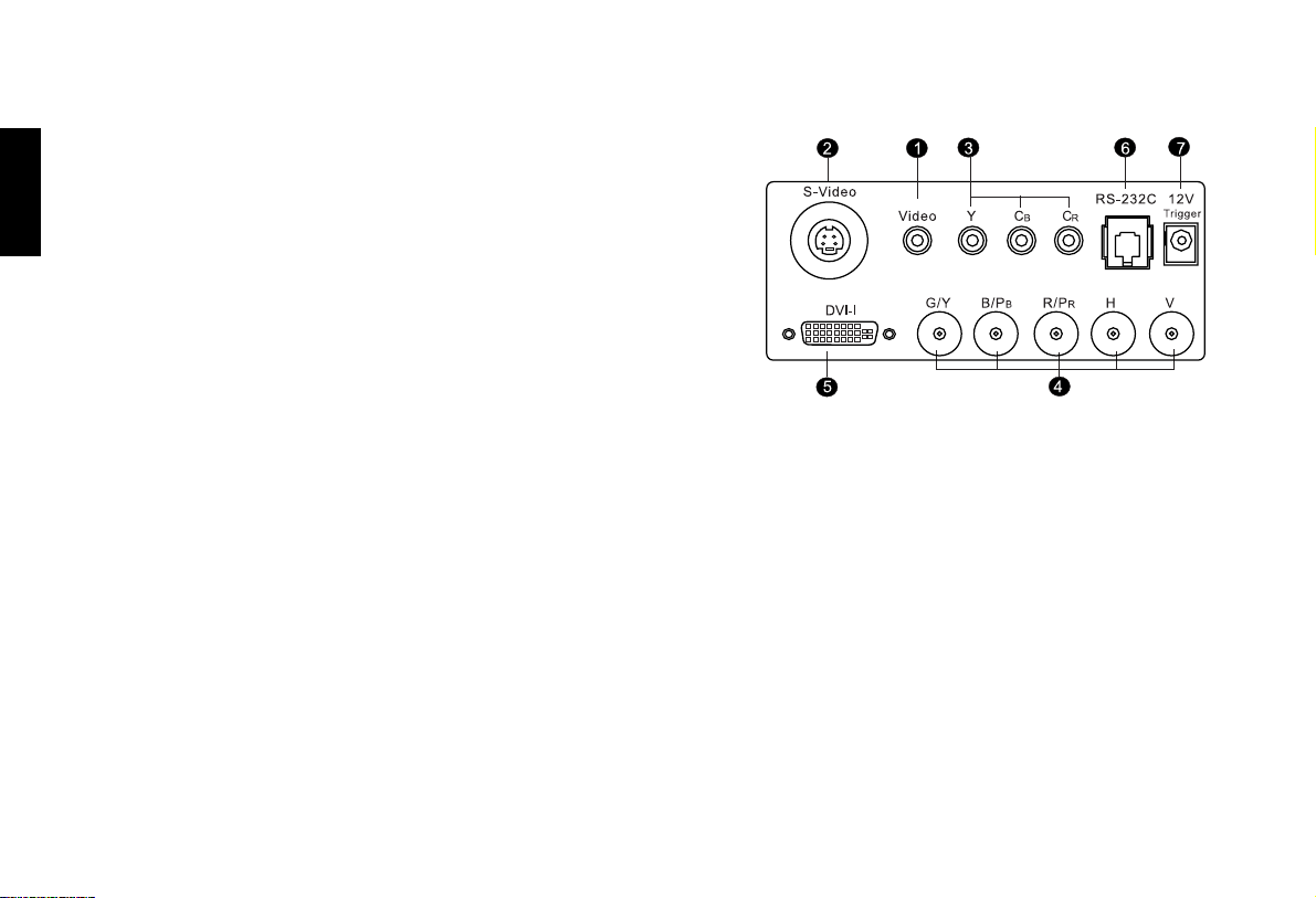
Connector Panel
1. Video (RCA Jack)
Composite video signal input.
2. S-Video (mini DIN 4-pin)
Y/C (S-video) signal input
3. Component (RCA Jacks)
480i Component (Y/CB/CR) video signal input
4. RGB/ HDTV (BNC) or Progressive Scan DVD players
DTV Y/PB/PR or DTV RGB video signal input.
5. DVI- I
Digital/ Analog signal input.
6. RS-232C (RJ-11 Jack)
RS-232C control signal input.
7. 12v Trigger (mini jack with the diameter of 5.5 mm outside and 2.5 mm inside)
+12V output, active when the projector is turned on.
14
Page 16
Remote Control
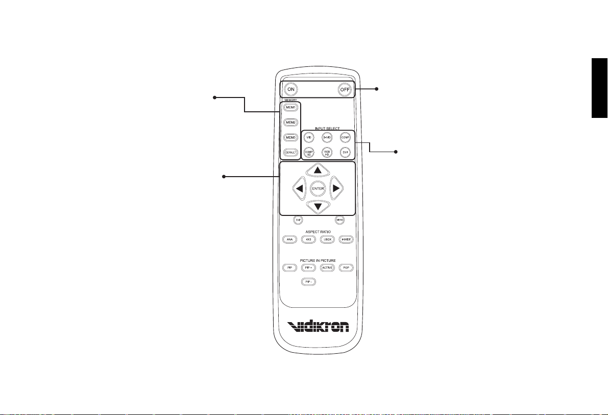
MEMORY
M1, M2, M3, DEFAULT
Recall video memory sequentially (see "Selecting
Video Memory" on page 30)
ARROW (c,e,d,f)
Use to select the menu or to make various
adjustments.
ENTER
Enter the setting of items in the menu.
ON
Hold down this button for ONE second to turn
on the unit.
OFF
Press this button to turn off the unit.
INPUT SELECT
VIDEO
Composite video signal input
S-VIDEO
S-Video signal input
COMP
Component Y/CB/CR input
COMP HD
DTV Y/PB/PR signal input
RGB HD
DTV RGBHV signal input
DVI
Digital/ Analog signal input
Overview
English
15
Page 17
English
Vidikron Owner’s Manual
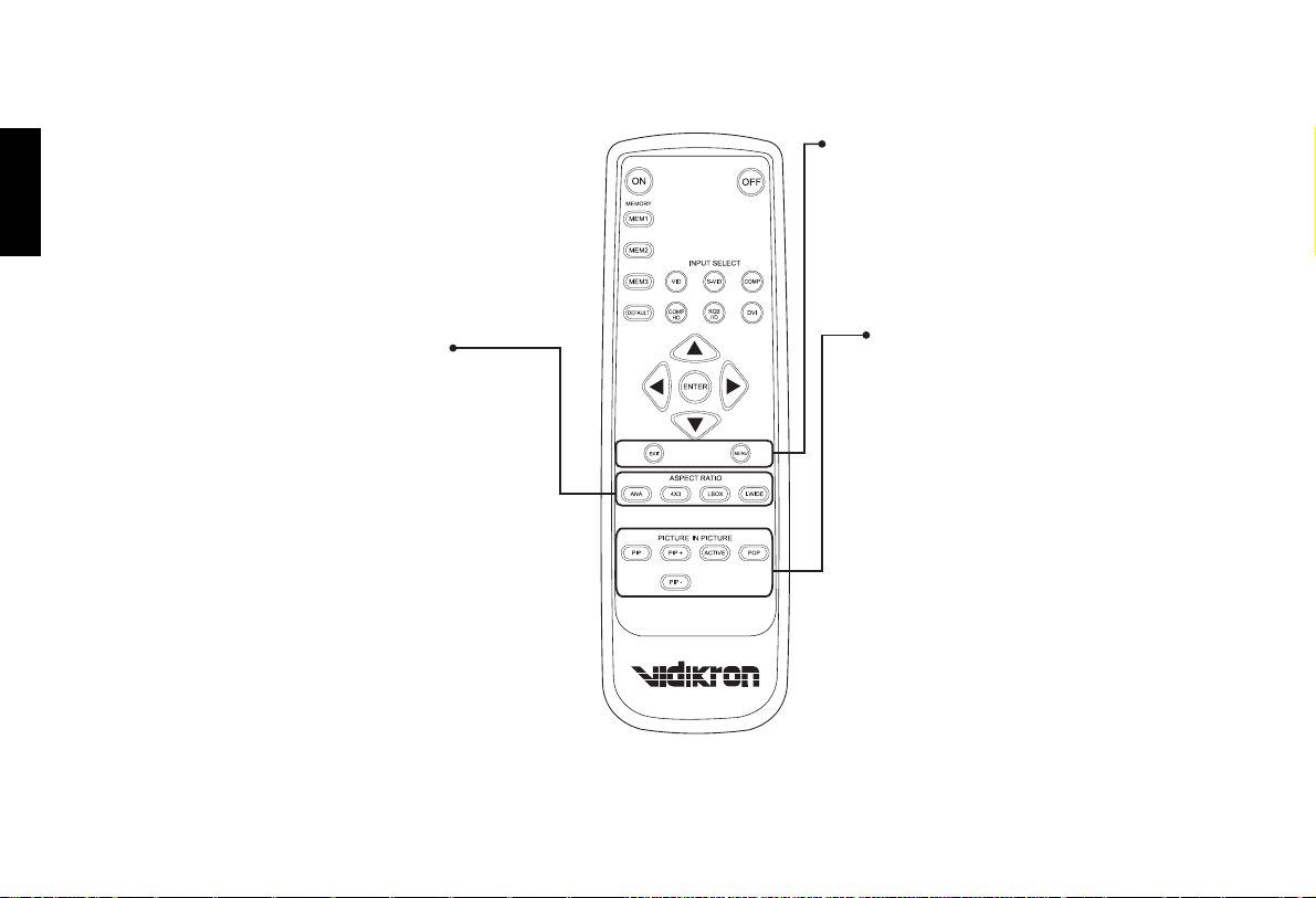
EXIT
Exit and save the setting(s) of items in the menu.
MENU
Turns on/off the on-screen display menu.
16
ASPECT RATIO
ANAMORPHIC
For 16: 9 DVDs.
4 X 3
The input signal will be scaled to fit 4: 3 display
mode in the center of screen.
LETTERBOX
Letterbox mode. Image in letter- box format is
enlarged to fit 16:9 full screen display and the
upper/lower portion are “blanked off”.
I-WIDE (IntelliWide)
4:3 image is enlarged nonlinearly in horizontal
direction to fit 16: 9 full screen display.
PICTURE IN PICTURE
PIP (Picture in Picture)
Enable the PIP function. Use ARROW keys to
adjust the position of the PIP window (see "PIP/
POP function" on page 32)
PIP+
Enlarge the size of PIP window.
PIP-
Shrink the size of PIP window.
ACTIVE
Switch to the active window in PIP display
mode.
POP (Picture On Picture)
Enable the POP function.
Page 18
Installation
Installation
Remote Control
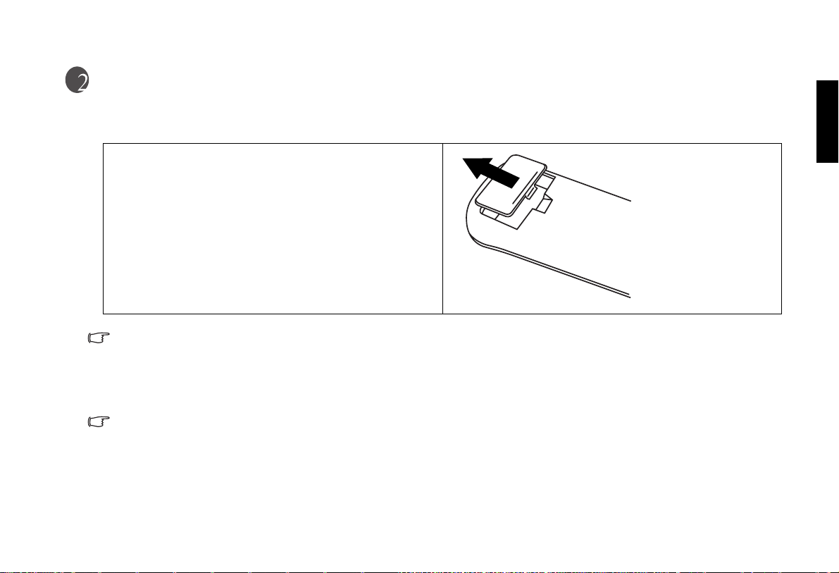
Push down on the tab and lift to open the cover. Install the two AAA
batteries with the correct polarity, then close the cover.
Notes on Batteries
■ Make sure that the battery polarities are correct when installing the batteries.
■ Do not mix an old battery with a new one or different types of batteries.
■ If you will not use the remote control for a long time, remove the batteries to avoid damage from battery leakage.
Notes on Remote Control Operation
■ Make sure that there is nothing obstructing the infrared beam between the remote control and the IR receiver on the projector.
■ The useable range is between 3m/ 9.8 feet (from the front of the projector) and 4m/ 13.1 feet (from the top of the projector) within a
30 degree horizontal angle and 15 degree vertical angle.
English
17
Page 19
English
Vidikron Owner’s Manual
Projector
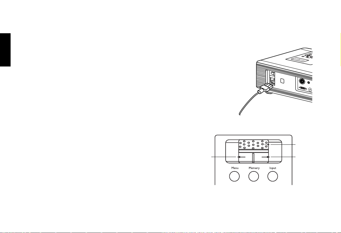
Connect the Power Cord
Plug the supplied power cord into the AC inlet in the rear of this unit. (AC 100V ~ 240V)
Turn on the main power switch on the rear of this unit (next to the AC inlet). The POWER LED
will light up in orange. Press ON key on the remote control for ONE second to turn on the unit.
Adjust the Lens Zoom/Focus ring
Adjust the projected image size you need with the zoom ring on the lens.
To focus the image, rotate the focus ring on the lens.
Focus
18
Zoom out
Zoom in
Page 20
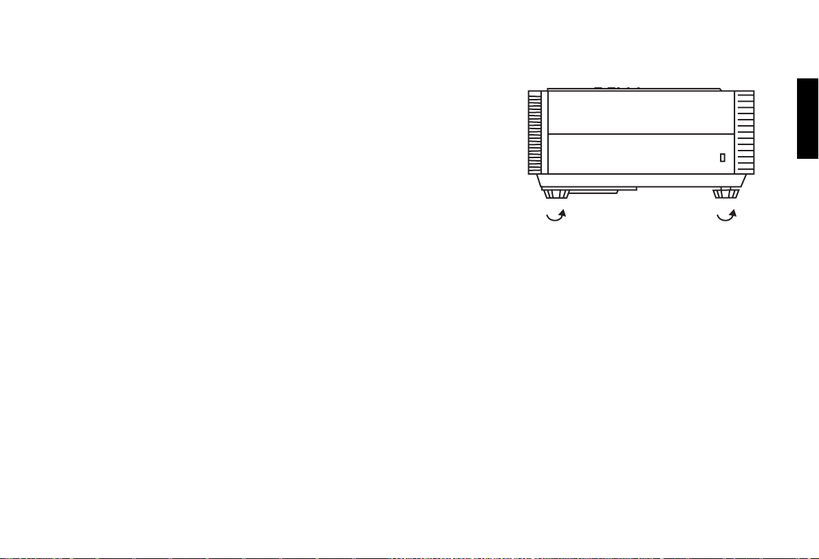
Adjust the height
There are 4 screw adjusters on the bottom of this unit. You can adjust the height or
projection angle of this unit by using these adjusters.
Installation
English
19
Page 21
English
Vidikron Owner’s Manual
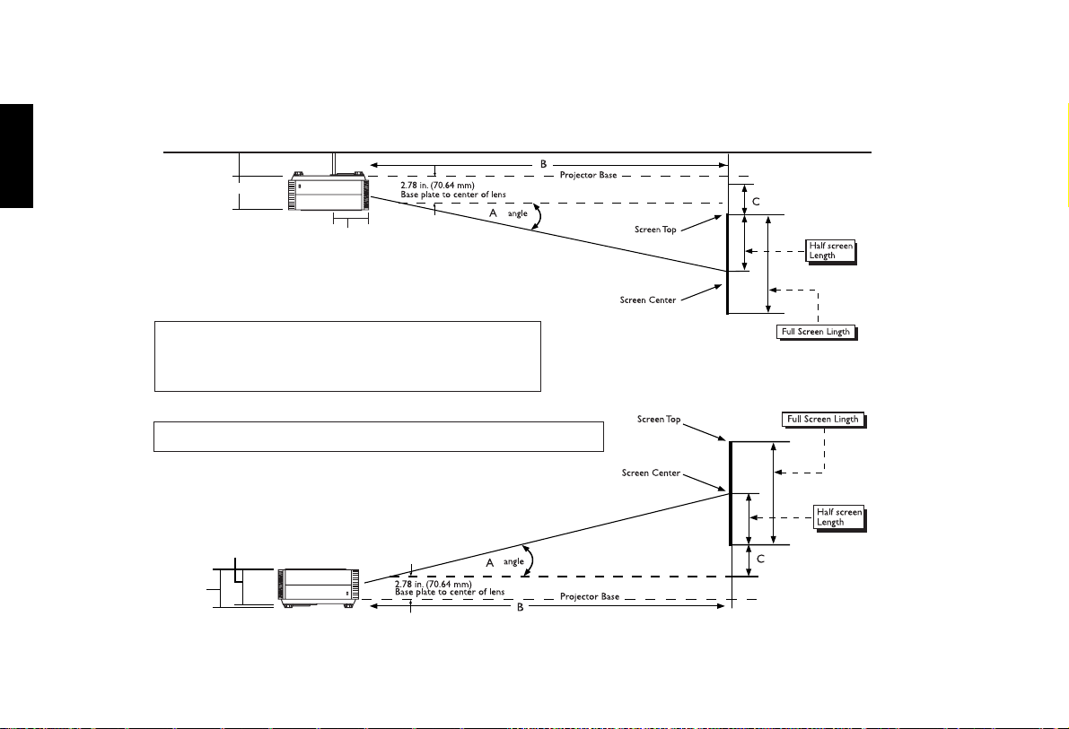
Installation For Vision Model 20 (With 1.71 - 2.06 Lens)
Ceiling
Between 6.10 - 27.36 in. (155 - 695 mm)
4.89 in. (124.2 mm)
5.51 in. (140 mm)
Screen __________ (H) x __________ (W)
B) THROW DISTANCE:
V2016x9Screens:
Minimum:(screenwidthx1.71)= __________inches
Maximum:(screenwidthx2.06)= __________inches
C) VERTICAL OFFSET:
Screenwidthx0.12=_________inchesfromthecenterofthelens.
Floor
4.89 in. (124.2 mm)
20
5.45 in.
(138.4 mm)
Page 22

Throw Distance Chart For Vision Model 20 (With 1.71 - 2.06 Lens)
Vision Model 20 @ 1024 x 576
Installation
English
Screen Height Screen Width Min Throw Distance
40.5 72 123.12 148.32 8.64
43 77 131.67 158.62 9.24
45 80 136.80 164.80 9.60
47 84 143.06 172.34 10.04
49 87 148.77 179.22 10.44
50 89 152.19 183.34 10.68
51.5 92 157.32 189.52 11.04
52 93 159.03 191.58 11.16
54 96 164.16 197.76 11.52
56 100 171.00 206.00 12.00
58 103 176.13 212.18 12.36
58.5 104 177.84 214.24 12.48
60 107 182.97 220.42 12.84
61 109 186.39 224.54 13.08
63 112 191.52 230.72 13.44
65 116 198.36 238.96 13.92
67.5 120 205.20 247.20 14.40
72 128 218.88 263.68 15.36
80 142 242.82 292.52 17.04
82 146 249.66 300.76 17.52
90 160 273.60 329.60 19.20
Max Throw
Distance
Vertical Offset
Position
Screen Hight Screen Width Min TD Max TD Vertical Offset
(SWx1.71) (SWx2.06) Screen Width x 0.12
21
Page 23
English
Vidikron Owner’s Manual
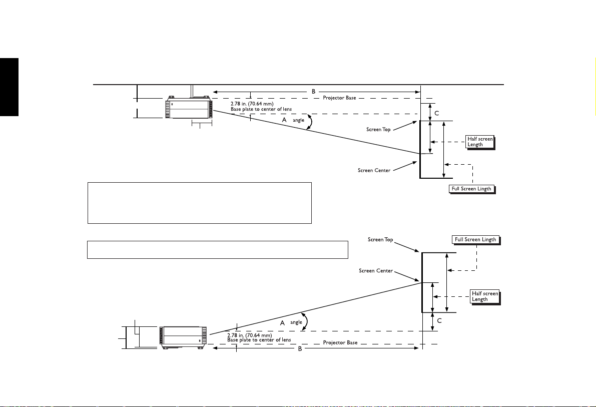
Installation For Vision Model 20ET (With 2.31 - 3.06 Lens)
Ceiling
Between 6.10 - 27.36 in. (155 - 695 mm)
4.89 in. (124.2 mm)
5.51 in. (140 mm)
Screen __________ (H) x __________ (W)
B) THROW DISTANCE:
V20ET 16x9Screens:
Minimum:(screenwidthx2.31) = __________inches
Maximum:(screenwidthx3.06) = __________inches
C) VERTICAL OFFSET:
Screenwidthx0.10 =_________inchesfromthecenterofthelens.
Floor
4.89 in. (124.2 mm)
22
5.45 in.
(138.4 mm)
Page 24

Throw Distance Chart For Vision Model 20ET (With 2.31 - 3.06 Lens)
Vision Model 20ET @ 1024 x 576
Installation
English
Screen Height Screen Width Min Throw Distance
40.5 72 166.32 220.32 7.20
43 77 177.87 235.62 7.70
45 80 184.80 244.80 8.00
47 84 193.25 256.00 8.37
49 87 200.97 266.22 8.70
50 89 205.59 272.34 8.90
51.5 92 212.52 281.52 9.20
52 93 214.83 284.58 9.30
54 96 221.76 293.76 9.60
56 100 231.00 306.00 10.00
58 103 237.93 315.18 10.30
58.5 104 240.24 318.24 10.40
60 107 247.17 327.42 10.70
61 109 251.79 333.54 10.90
63 112 258.72 342.72 11.20
65 116 267.96 354.96 11.60
67.5 120 277.20 367.20 12.00
72 128 295.68 391.68 12.80
80 142 328.02 434.52 14.20
82 146 337.26 446.76 14.60
90 160 369.60 489.60 16.00
Max Throw
Distance
Vertical Offset
Position
Screen Hight Screen Width Min TD Max TD Vertical Offset
(SWx2.31) (SWx3.06) Screen Width x 0.10
23
Page 25

Vidikron Owner’s Manual
English
Connecting
When connecting, make sure to:
1. Turn off all equipment before making any connections.
2. Use the correct signal cables for each source.
3. Ensure the cables are firmly connected.
24
Page 26
Connecting Video Inputs
Video / S-Video / Component (Interlaced Video)
Connecting
English
DVD Player
25
Page 27
Vidikron Owner’s Manual
English
Progressive Component (DTV Y/PB/PR)
DTV Source
26
Page 28
Connecting
RGBHV (DTV RGB)
DTV Source
The RGB BNC input supports two kinds of HDTV formats: Progressive component (DTV Y/PB/PR) and DTV RGB. The unit will detect the
resolution automatically.
English
27
Page 29
English
Vidikron Owner’s Manual
Connecting a Computer or HDCP Compatible Video Device With DVI-I Output
PC, Notebook, set top box
or other video device with
DVI output
This unit is compatible with the following computer resoultions: 1280x720, 1024x768, 800x600, 640x480.
28
Page 30
Basic Operation
Basic Operation
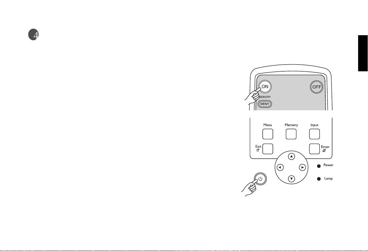
Turning on the Power
■ The Power LED lights orange when power is applied and the power switch is turned
on.
■ Press and hold the ON key on the remote control or the Power key on the projector
for ONE second to turn on the unit. The POWER LED will blink orange during
warm up period, then light solid green.
■ " Searching…." will be displayed on the screen before the projector identifies the
input signal. This message will remain on the screen until a valid signal is detected.
■ If an incompatible input signal exceeds the range of the projector a "Not supportive
timing" message will be displayed on the screen. This message will remain on the
screen until you change the input signal.
English
29
Page 31
English
Vidikron Owner’s Manual
Zoom/ Focusing
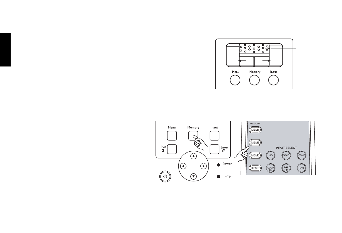
■ Adjust the projection image size you need with the zoom ring on the
lens. To focus the image, rotate the focus ring on the lens.
Focus
Selecting Video Memory
■ Press MEM1, MEM2, MEM3 buttons to recall
settings in the memory.
■ Press DEFAULT to select the default setting.
30
Zoom out
Zoom in
Page 32
Selecting Input Source
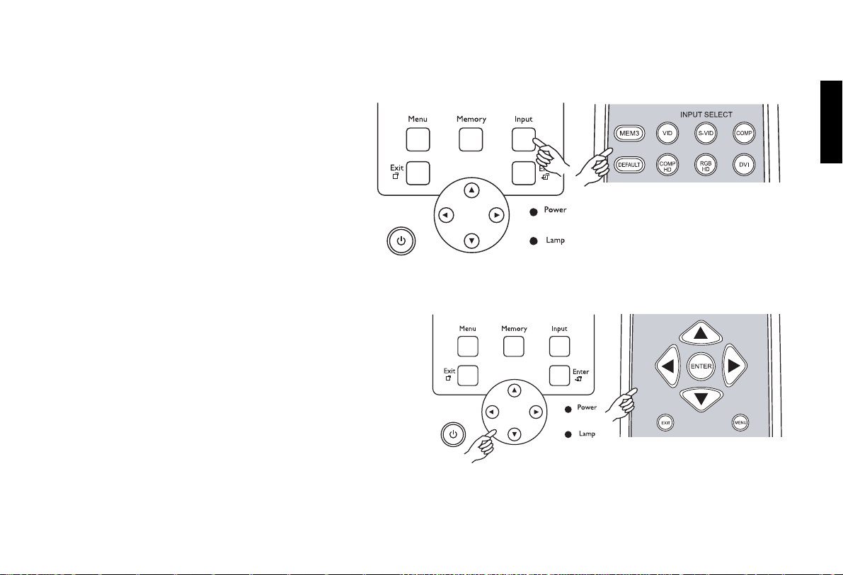
■ When this unit is turned on, it will search for
the input source you last selected.
■ You may select the input source directly on
the remote control.
Setting Menu
■ Press the Menu button to turn on /off the on-screen menu.
■ Use the ARROW buttons (c,e,d,f) to select the menu or
to make various adjustments.
■ Press the Enter or f button to enter the setting of items in
the menu, or press the Exit button to leave and save the
setting of items in the menu.
■ For more detailed settings, see Chapter 5 Menu on page 34.
■ Press Picture to access the picture setting menu.
Basic Operation
English
31
Page 33
English
Vidikron Owner’s Manual
Selecting "ASPECT RATIO"
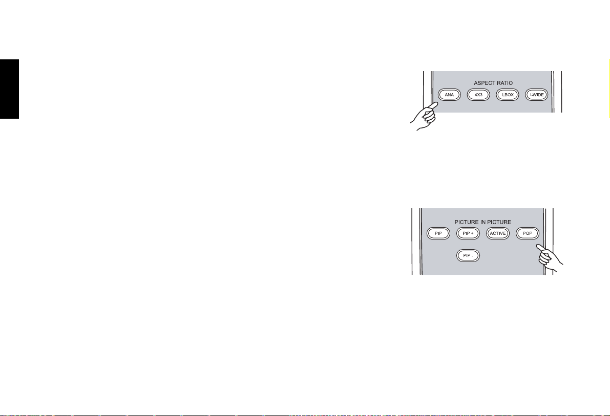
■ Select the proper aspect ratio according to the content being used. There are four aspect
ratios for choice.
■ ANAMORPHIC: The image is compressed vertically, but anamorphic
software will appear properly proportioned. This is best suited for use with
16:9 DVD's.
■ 4 X 3: The input signal will be scaled to fit 4 : 3 display mode in the center
screen.
■ LETTERBOX: Image in letterbox format is enlarged to fit 16:9 full screen
display and the upper/lower portion are cropped.
■ I-WIDE: This transforms a 4x3 image to a 16x9 image.
PIP/ POP function
■ Press the PIP button to enable the PIP function.
■ For PIP purposes, there are two groups of inputs separated by their display modes:
Video Group: Video, S-Video and Component Y/C
Graphic Group: HDTV input and Computer input.
■ The PIP can show one input from the Graphic Group within one input from the Video
Group, or show one input from Video Group within one input from the Graphic Group.
■ Press the PIP button to switch to the main window or turn off PIP function.
■ Select the input source of the main window by pressing the INPUT button.
■ Press the ACTIVE button to switch to the active window. You can change the input signal setting in the active window.
■ Press PIP+ or PIP- to adjust the size of PIP window.
■ Adjust the position of the PIP window with the ARROW keys (c,e,d,f).
■ Press POP to enable the POP function.
B/CR inputs
32
Page 34
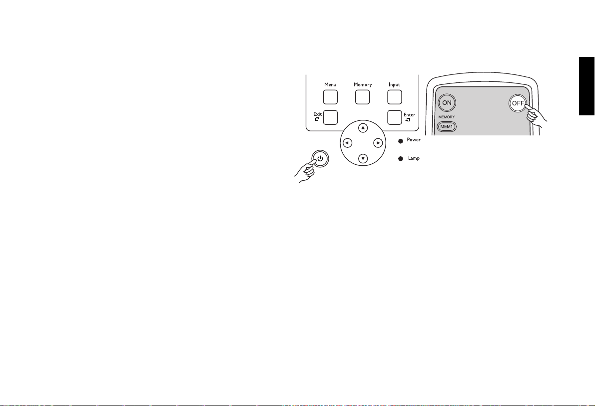
Turning off the Power
■ Press the OFF key on the remote control to turn off the
unit.
■ The POWER LED will blink green and the fans will
speed up for a quick cool down. The projector will not
respond to any command for 90 seconds.
■ The POWER LED will light solid orange once the
cooling down cycle has completed.
■ Fans will run for three minutes to cool.
■ You may turn the projector back on after the first 90
seconds.
Basic Operation
English
33
Page 35
Vidikron Owner’s Manual
English
Menu
Using the Menu
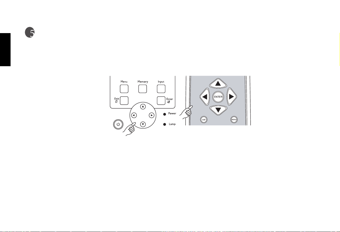
This unit is equipped with an on-screen display (OSD) menu for making various adjustments and settings.
There are five different menu languages; see page 40 Language setting for more details.
■ Press the Menu button to turn on /off the on-screen display menu.
■ Use the ARROW buttons (c,e,d,f) to select the menu or to make various adjustments.
■ Press the Enter or f button to enter the setting of items in the menu, or press the Exit button to leave and save the setting of items in the
menu.
34
Page 36
Main Menu
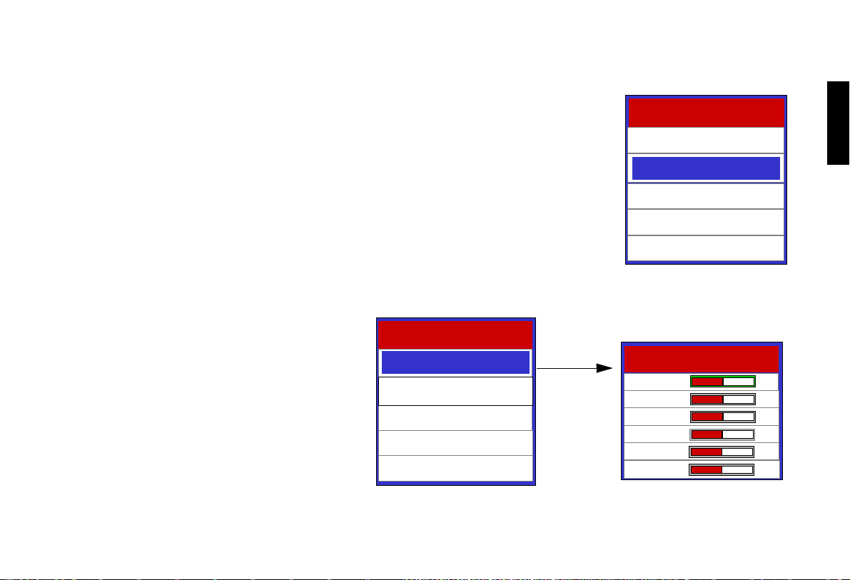
When the Menu button is pressed on the remote control, the main menu will appear on-screen. An
example of the main menu is shown right. Use c or d button to move the item you want to choose
and then press the Enter or f button.
Picture Quality Adjustments
To access the picture quality adjustments, press
Menu, highlight Picture Adjust and press Enter
or f. The picture adjust sub-menu will then appear
(see above).
To make an adjustment to a particular function,
highlight the function with the c or d arrow button and press Enter or fto activate a scroll bar for
that adjustment. When all the settings are done,
press Exit to leave the current submenu and then
go to Image options --> Memory Store for saving
the values as Memory 1, Memory 2 or Memory 3.
Vision Model 40
Picture Adjust
Image Options
Status
Install
Service
Menu
Vision Model 40
Picture Adjust
Image Option
Projector Status
Install
Install
Service
Picture Adjust
Brightness +30
Contrast +15
Color +30
Tint +15
Sharpness 0
Color Temp. 4
English
35
Page 37
English
Vidikron Owner’s Manual
Image Options 1
Image Options
Input Select
36
Input Select
Aspect Ratio
HD/RGB Adjust
Memory Store
Memory Recall
Aspect Ratio
Anamorphic
Standard (4/3)
Letterbox
IntelliWide
Input Select
Video
S-Video
Component
Component HD
RGB HD
DVI-I
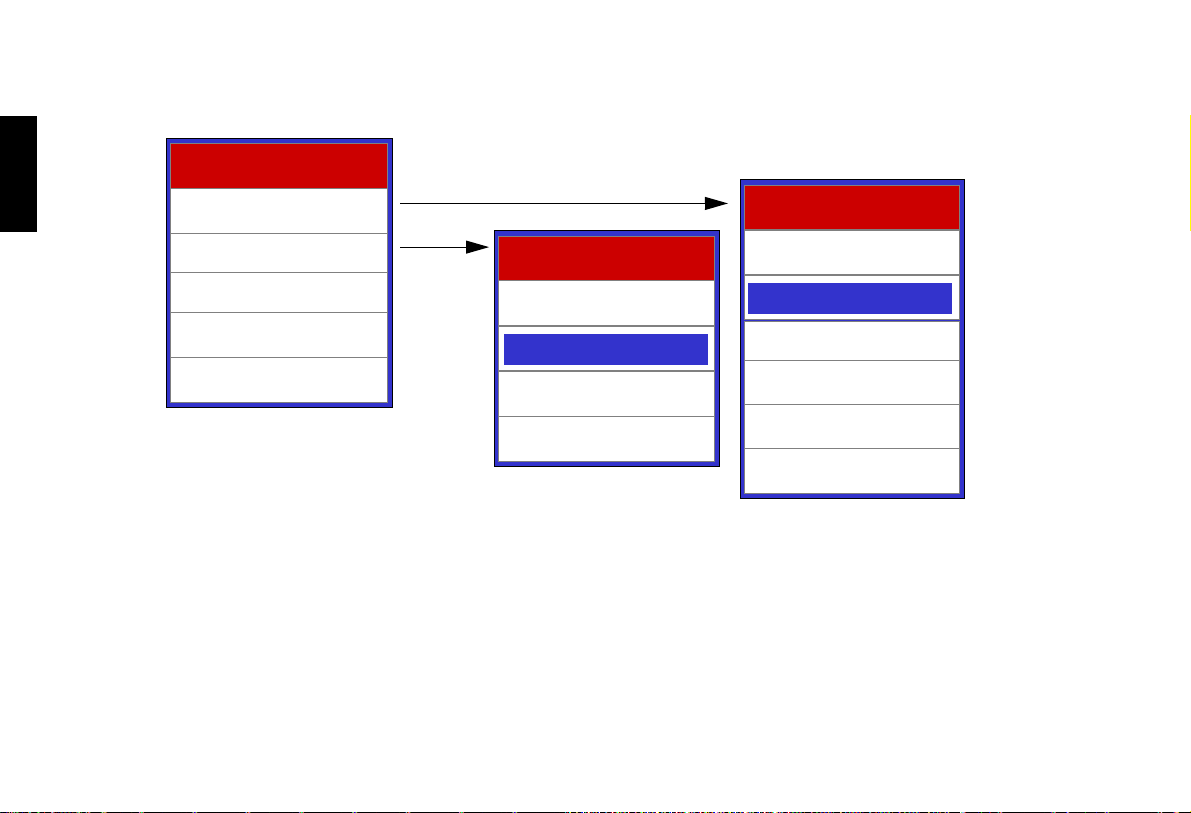
From Input Select submenu, you are free to choose one of the 6 input sources as long as you are sure the projector is connected with the
correct signal cables. In the example above, S-Video is the current source.
Page 38

Aspect Ratio
There are four aspect ratios available that can be selected for video signal inputs.
16:9 Screens:
■ Anamorphic: The image is compressed vertically, but anamorphic software will appear properly
proportioned. This is best suited for use with 16:9 DVD's.
■ Standard (4/3): The input signal will be scaled to fit in the center of the 16:9 screen.
■ Letterbox: The image in the Letterbox mode will be zoomed in, and the top and bottom portion
'blanked off'. This ratio is best suited for LaserDisc movies or non-anamorphic DVD's.
■ I-WIDE: A 4:3 image is transformed into a 16:9 image.
Active Image Area
Active Image
Area
Active Image Area
Menu
English
37
Page 39
English
Vidikron Owner’s Manual
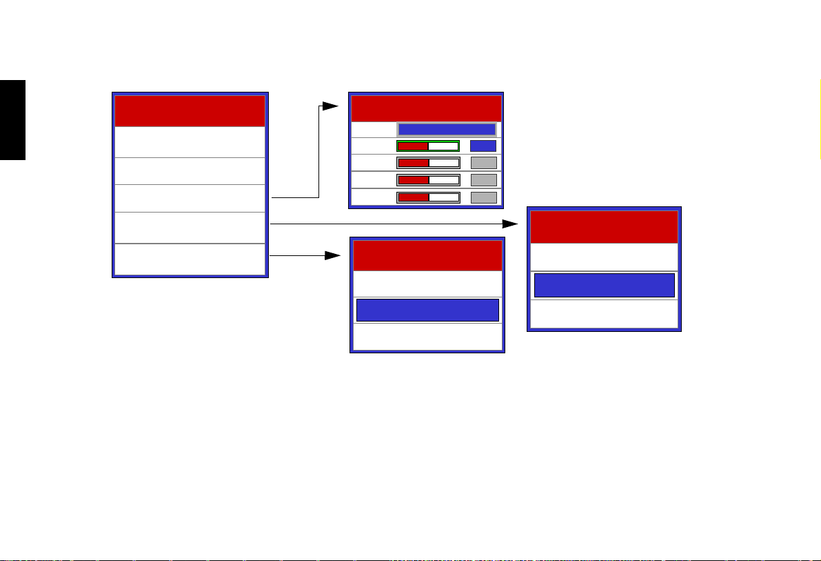
Image Option 2
Image Options
Input Select
Aspect Ratio
HD/RGB Adjust
HD/RGB Adjust
Auto.
Freq.
Phase
H. Pos.
V. Pos.
YES ?
0
0
0
0
38
Memory Store
Memory Recall
Memory Recall
Memory 1
Memory 2
Memory Store
Memory 1
Memory 2
Memory 3
Memory 3
HD/RGB Adjust.: The following settings are only available with a PC or DTV RGB signal. There is no position adjustment when using
DVI-D signal.
■ AUTO: Adjusts the phase, frequency and position automatically.
■ Freq.: Adjusts the frequency of the signal.
■ Phase: Adjusts the phase of the input signal.
■ H. Pos.: Adjusts the horizontal position of the image.
■ V. Pos.: Adjusts the vertical position of the image.
To enter into the memory selection menus, use Memory Store and Memory Recall menus to save and load up to three different memories.
There are three memories: Memory 1, Memory 2 and Memory 3.
Page 40
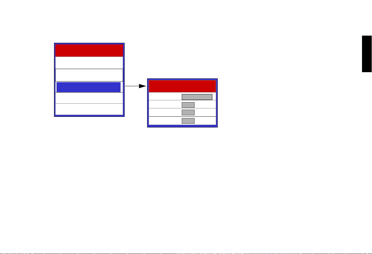
Projector Status
Vision Model 40
Picture Adjust
Image Options
Menu
English
Status
Status
Install
Service
Default: Use this function to reset all values of the current source back to factory default.
Sleep Timer: To setup auto off timer. The setting timer is from 10 minutes to 3 hours.
Lamp Hours: To check for total time of lamp usage.
Projector Status
Default
Sleep Timer Minutes
Lamp Hours Hours
Load
60
+63
+59
M
Minutes
39
Page 41
English
Vidikron Owner’s Manual
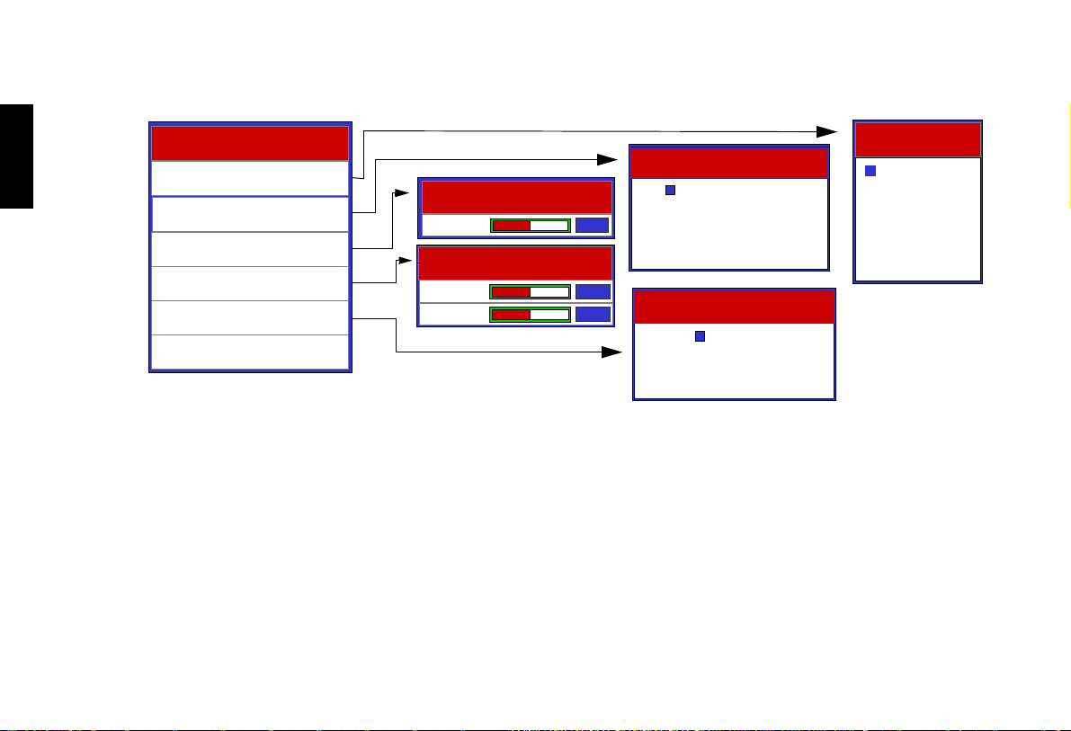
Install
Install
Language
Picture Configuration
Keystone
OSD Position
Background Color
Test Patterns
Press Enter on selected feature to open the Install menu.
Language: There are 5 different menu languages available: English, French, Spanish, German and Italian.
Picture Orientation: The projector can be installed on a ceiling or in a rear screen configuration with one or more mirrors. There are four
settings: FLOOR FRONT, CEILING FRONT, FLOOR REAR, and CEILING REAR.
Keystone: Corrects the trapezoidal distortion as a result of the angle of projection (-12° ~ +12°). This can correct for up to +/- 12 degrees of
offset.
OSD Position: To adjust horizontal and vertical positions of the OSD.
Background Color: To select the background color while there is no input signal detected.
Test P a tte r ns: Highlight and press Enter or the right arrow key to display the cross-coarse pattern.
Keystone
Keystone
OSD Position
H. POS.
V. POS.
Picture Configuration
Floor Front
0
0
0
Ceiling Front
Floor Rear
Ceiling Rear
Background Color
Grey
Blue
White
Language
English
Francais
Espanol
Deutsch
Italiano
40
Page 42
Service
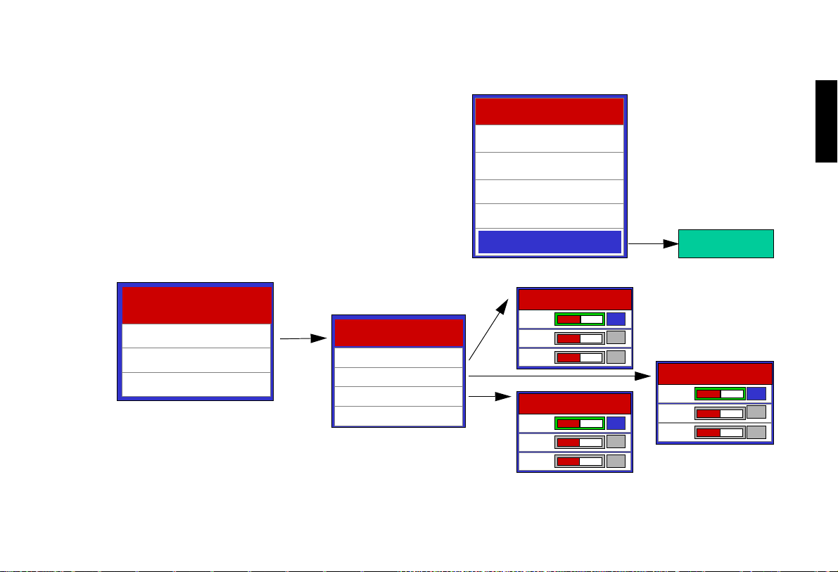
The Service menu is passcode protected and for use by Vidikron personnel only. Many of the adjustments available in this section are
intended for use by trained service personnel only. If you are having
difficulty with one of these items, please contact your Vidikron Dealer
for service.
White Balance
Service
White Balance
White Balance
Blue Enable
Lamp Reset Timer
To adjust grey scale.
■ Gamma: Adjust the gamma curve.
■ Gain: Adjust high end.
■ Offset: Adjust low end.
■ Store Settings: When this function is selected and entered, all White Balance
settings will automatically be stored in Color Temp. 4 (Custom Temperature).
White Balance
Gamma
Gamma
Gain
Gain
Offset
Offset
Store Settings
Store Settings
Vision Model 40
Picture Adjust
Image Options
Status
Install
Service
Gamma
Gamma
Red
Red
Green
Green
Blue
Blue
Offset
Offset
Red
Red
Green
Green
Blue
Blue
66
66
66
66
66
66
Menu
English
Please enter pass-code
to access Service screen
Gain
Red
0
0
0
0
0
0
Green
Blue
134
512
512
41
Page 43
Vidikron Owner’s Manual
English
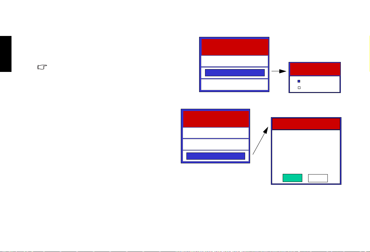
Blue Enable
This mutes the red and green image.
Use this function in combination with the external color bar pattern to
adjust for proper color and tint settings without using a blue filter.
To quickly exit this function, select any other color temperature in the
same adjustment window and return to the original temperature setting
or simply select another input source from the remote control and then
return to the original selected source.
Reset Lamp Timer
Use this function to reset lamp usage counter. Reset only if
you replace the lamp.
Service
White Balance
Blue Enable
Lamp Reset Timer
Service
White Balance
Blue Enable
Lamp Reset Timer
Blue Enable
Blue Enable
Off
OffOnOff
On
On
Lamp Reset Timer
Reset only if you
replace new lamp
ARE YOU SURE?
NO
Yes
42
Page 44
Additional Information
Additional Information
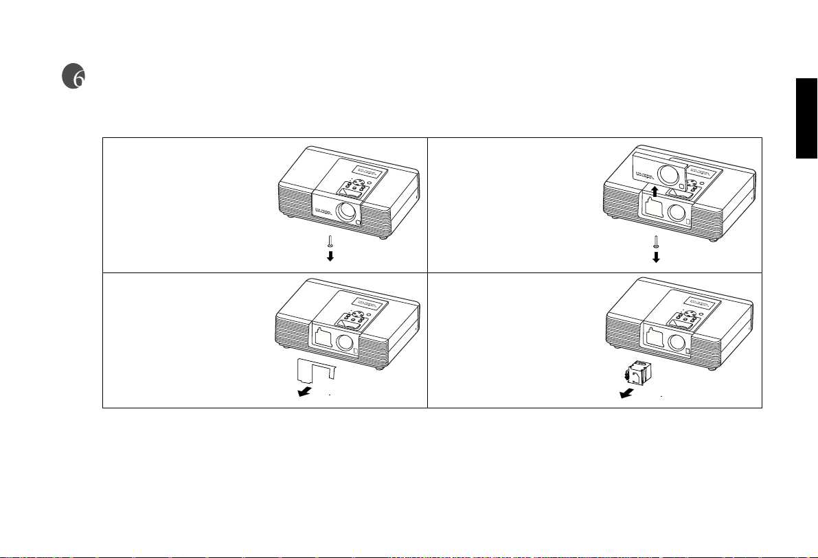
Replace the Lamp (Contact your Vidikron Dealer)
1. Loosen the screw of front
lamp cover.
3. Loosen the three screws
on the lamp shield.
4. Take off the lamp shield.
2. Take off the front lamp
cover.
5. Loosen the two screws on
the lamp module.
6. Pull out the lamp module
horizontally.
English
43
Page 45
Vidikron Owner’s Manual
English
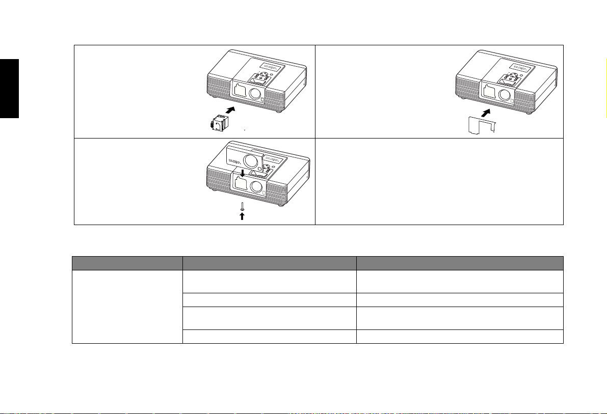
7. Insert the new lamp module into the projector horizontally until it is securely
in place.
8. Tighen the two screws on
the lamp module.
11. Put on the front lamp cover.
12. Tighten the screw of front
lamp cover.
9. Put on the lamp shield.
10. Tighten the three screws on
13. Turn on the power and go into the
Troubleshooting
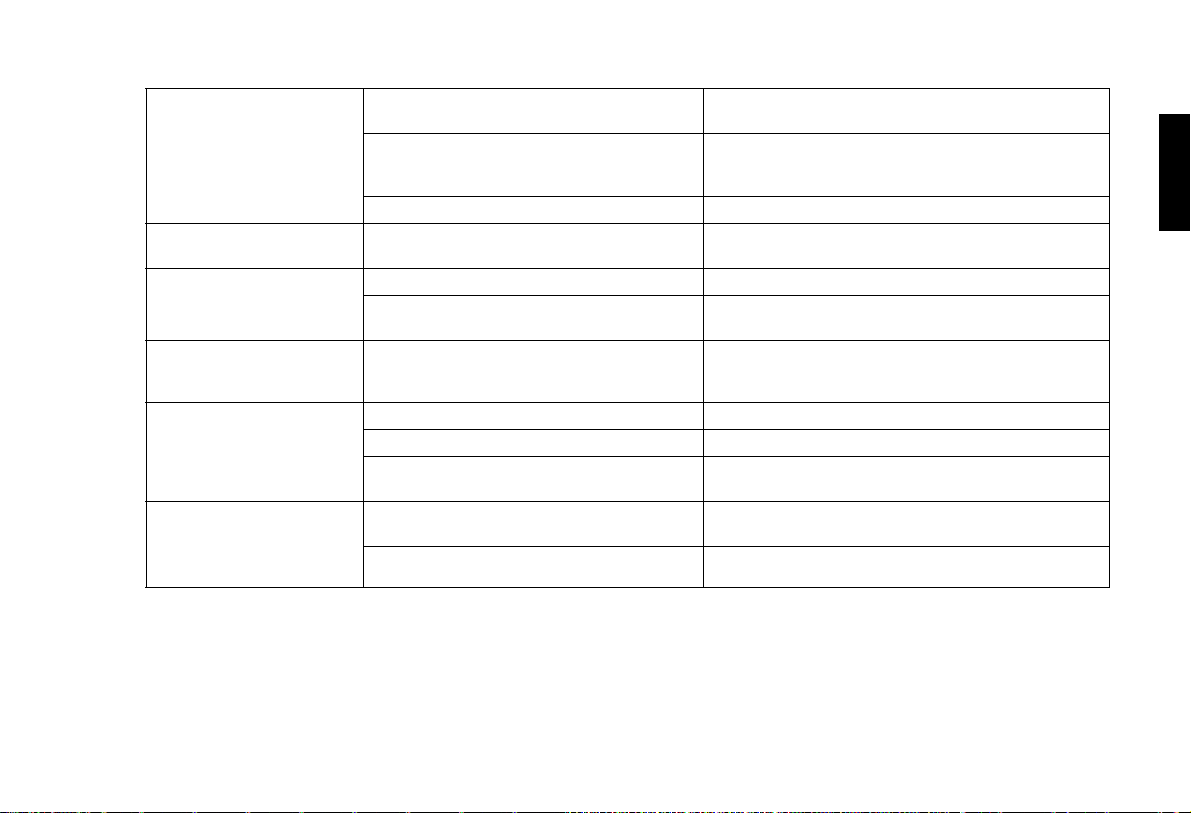
Problem Possible Cause Remedy
There is no power from power cable. Plug the power cord into the AC inlet on the rear of this
This unit does not turn
on.
The power switch is not turned on. Turn on the power switch.
Turned on this unit again while still in the cooling down procedure.
The front lamp cover is not correctly attached. Correctly attach the front lamp cover.
the lamp shield.
Service menu, select
Lamp Reset Timer item to reset lamp usage counter.
unit, and plug the power cord into to the power outlet.
Wait until this unit completes the cooling down procedure.
44
Page 46
Additional Information
No picture
Image is unstable
Picture is blurred
Remote control does
not work correctly
LAMP LED blinks in
red
POWER LED blinks in
orange and green
sequentially
This unit is not correctly connected to the input
source device.
The input signal has not been correctly selected. Select the correct input signal with the input keys: Video,
POWER LED or LAMP LED blinking. Please contact your Vidikron dealer for assistance.
The connection cables are not connected to this
unit.
The projection lens is not correctly focused. Adjust the focus of projection lens with the focus ring.
This unit and the screen are not aligned
squarely.
The batteries are exhausted. Replace both batteries with new ones.
The front lamp cover is not correctly attached. Correctly attach the front lamp cover.
The cooling fan does not work properly. Please contact your Vidikron dealer for assistance.
The temperature inside this unit is extremely
high.
The lamp has exceeded its specified usage
hours.
The lamp has burned out. Replace the lamp with a new one.
Check the connection.
S-Video, Component, Component HD, RGB HD and
DVI-I on the remote control.
Correctly connect the cables to the appropriate terminals.
Adjust the projection angle and direction, and the height
of this unit.
Check that the ventilation holes are not blocked.
Replace the lamp with a new one.
English
45
Page 47

Specifications
Projector Type
Digital Light Processing™ (DLP™), Single DMD™ Chip
Native Resolution
1024 x 576, (16:9)
Aspect Ratios
4:3, Letterbox, 16:9 Anamorphic, IntelliWide
Video Standards
NTSC, PAL
Throw Distance
V20: 1.71 to 2.06/ V20ET: 2.31 to 3.06
(Factor x Screen Width)
Light Output
CSMS** Specifications:
Home Theater Calibration:
457 ANSI Lumens, 17.55 Foot-Lamberts (fL)
850 ANSI Lumens*
Contrast Ratio
CSMS** Contrast Ratio: 120:1
1500:1 ANSI
Lamp
210W
Estimated Lamp Life
2000 hours @ 6500
DTV Compatibility
480p, 720p, 1080i
Memories
21 memories
Vision Model 20/ Vision Model 20ET Specifications
: Please refer to page 20 to page 23.
o
Kelvin
Additional Information
Inputs
(1) Composite Video, (1) S-Video,
(1) RGB/Component (via BNC),
(1) RCA Component Video,
(1) DVI-I w/ HDCP, (1) RS-232
Scan Frequency:
Horizontal 15-80 kHz, Vertical: 50-100 Hz
Picture Size (16:9 Screen)
Recommended Width: 72-96 in., Maximum Width: 200 in.
12V Output
Max. 250 Amp, active when the projector is on
Power Requirements
100-240V AC, 50/60 Hz, 310 watts
Operating Environment
40°- 95° F, (5°- 35° C), 20%-80% Humidity (non-condensing)
Dimensions (w/out feet)
Width: 15.8 in. (400 mm),
Depth: 11 in. (280 mm),
Height: Without feet 4.9 in. (125.41 mm)
with feet 5.18 in. (131.5 mm)
Weight: 17.5 lbs. (7.8 kg) (includes lens)
Regulatory Approvals
UL, FCC, CE, C-Tick
Limited Warranty:
Projector:
(2) Two year parts and labor from the date of deliv-
ery to the end user
Lamp Warranty: (6) six months or 1000 hours
English
46
Page 48

Additional Information
*ANSI Lumen specification:
This is the typical projector luminosity (brightness) specification found in most sales literature. This measurement is included in Vidikron
literature to allow for direct comparison with other manufacturer's projectors. These measurements can be taken at 9,000 to 13,000 degree
Kelvin to get expected performance data when the projector is used in professional, commercial, and industrial displays.
**CSMS Home Theater Calibration ANSI Lumen Specification:
These measurements are taken from the projector as setup in a home theater environment. The projector is calibrated to ISF specifications
including setting the color temperature to 6500 degree Kelvin, the standard for reproducing video.
**CSMS Home Theater Calibration foot-Lambert (fL) Specification:
This is the unit of measurement used in commercial movie theaters to express image brightness. The Society of Motion Picture and Television Engineers (SMPTE) specifies 16 fL as the target image brightness for film-based projectors using an open gate (without film in the projector). More importantly, today SMPTE specifies 12 fL as the target image brightness in Digital Cinema theaters using DLP™ technology.
The foot-Lambert is dependant on screen size, screen gain, and projector light output.
All measurements are made at Vidikron to ANSI/NAPM IT7.228-1997 specifications using the Photo Research PR-650 SpectraColorimeter
and Minolta LS-100 Light Meter, Video Essentials test DVD, and a Stewart Filmscreen StudioTech 130, 1.3 gain, 72-inch wide screen. The
projector is calibrated to a color temperature of 6500º Kelvin and has a minimum of 150 hours of usage.
English
47
Page 49
English
Vidikron Owner’s Manual
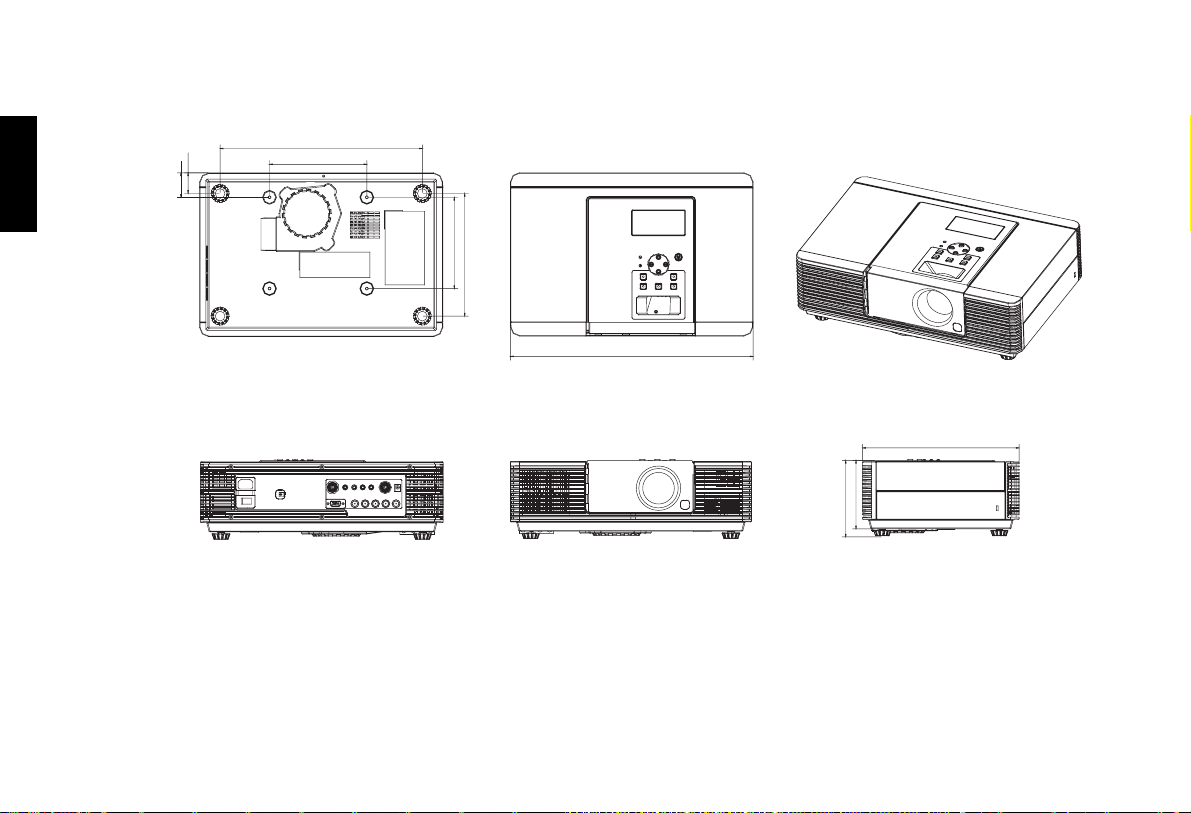
Dimensions
33.76
40
332.49
160
149.99-150.01
201.48-201.50
400
280
125.41
131.5
Unit: mm
48
Page 50
RS-232 Setup
Baud Rate: 115200 or 9600
Parity: None
Data Bits: 8 Bits
Stop Bits: 1 Bit
Flow Control: None
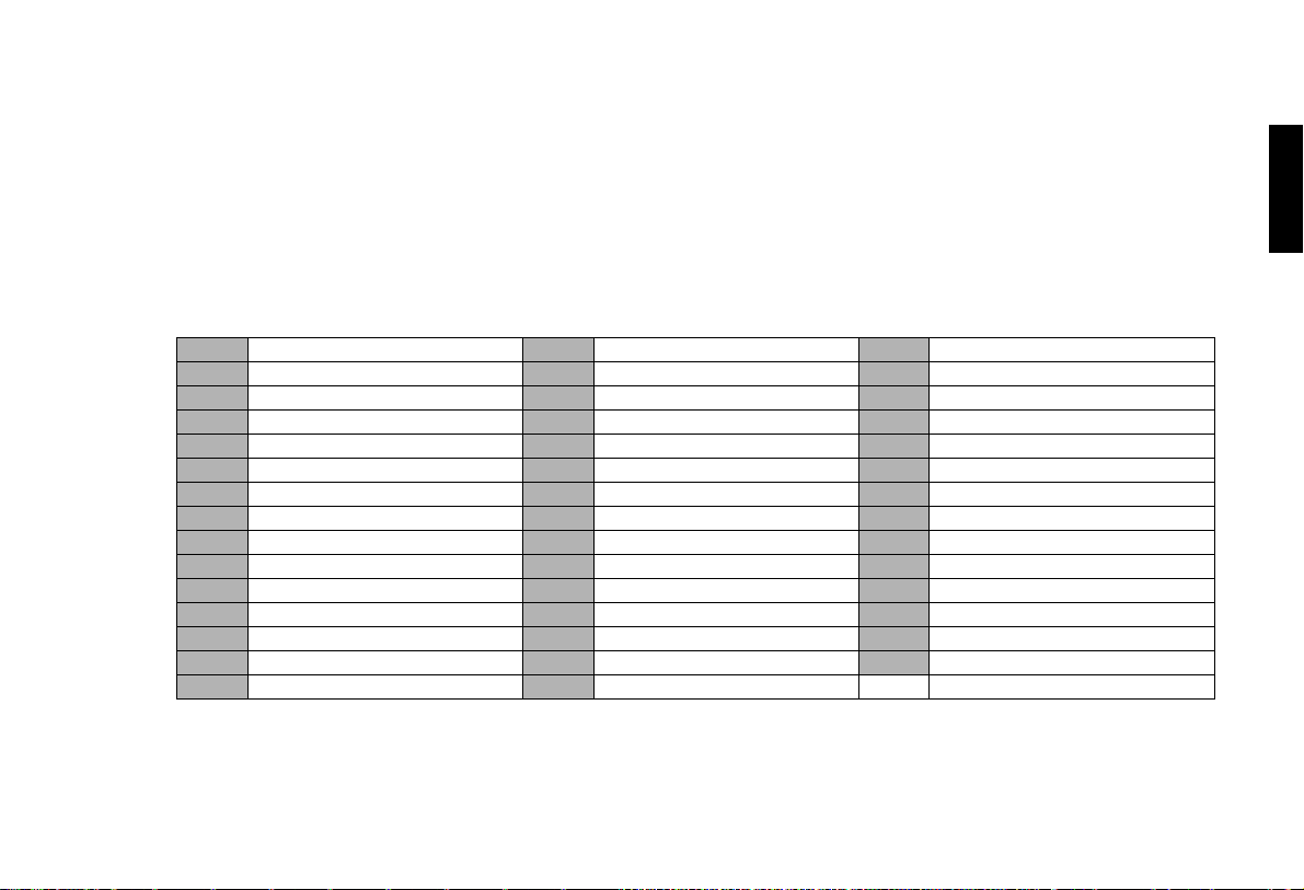
RS-232C Control Codes
Code Function X23 Switch to DVI_PC input X56 Picture in picture display
X01 Power On X24 Switch to YPBPR input X57 Picture by picture display
X02 Power Off X25 Switch to BNC_PC input X60 Switch language - English
X03 Message On X35 Anamorphic X61 Switch language - French
X04 Message Off X36 Standard X62 Switch language - Spanish
X10 Menu (arrow key) X37 Letter box X63 Switch language - German
X11 Enter (arrow key) X38 I-WIDE X64 Switch language - Italian
X12 Exit (arrow key) X40 Load memory 1 settings X85 Graphic Input - auto
X13 Up (arrow key) X41 Load memory 2 settings X90 Image orientation - floor front
X14 Down (arrow key) X42 Load memory 3 settings X91 Image orientation - ceiling front
X15 Left (arrow key) X46 Load default of current source X92 Image orientation - floor rear
X16 Right (arrow key) X47 Save memory 1 settings X93 Image orientation - ceiling rear
X20 Switch to Composite input X48 Save memory 2 settings X94 Back light on
X21 Switch to S-Video input X49 Save memory 3 settings X95 Back light off
X22 Switch to Component input X55 Switch active source
Additional Information
English
49
Page 51

Vidikron Owner’s Manual
English
PC Out Adapter
1. 1. Connect D-Sub 9-pin female to RJ-11 adapter (not
included) to Com port on PC.
2. 2. Connect RJ-11 to Projector.
RJ-11 to D-Sub 9-pin (not included)
RS-232 For D-Sub 9-pin (not included)
D-Sub 9-pin female Details
2TxT
3RxD
5 Ground
1, 4, 6, 7, 8, 9 NC
War ning: During initial turn on and turn off of the projector, this
unit will not accept RS-232 codes for 20 seconds.
D-Sub 9-pin female
RS-232 For RJ-11 (not included)
4-pin RJ-11 Details
2TxT
3RxD
1, 4 Ground
Yellow
Green
1
2
3
4
1
345
2
6
89
7
NOTE:
1. All codes are in the ASCII format.
Black
Red
Yellow
Green
Black
Red
2. A carriage return is required after each command.
50
Page 52

 Loading...