

VIDEO DOMAIN TECHNOLOGIES MEMOCAM, MEMOCAM DVR, MEMOCAM PLUS/S, MEMOCAM DVR/S, MEMOCAM PLUS Installation Manual
Page 1

Installation Manual
MemoCam®
MemoCam®Plus
MemoCam®DVR
MemoCam®Plus/S*
MemoCam®DVR/S*
Page 2

Version 3.2.002
PN/V7140001
Page 3

Copyright Video Domain Technologies Ltd.
The information in this manual was accurate and reliable at the time of its
release. However, Video Domain Technologies Ltd. reserves the right to
change the specifications of the product described in this manual without
notice at any time. As such, the descriptions and data included in this
document may not be current. Video Domain Technologies Ltd. assumes no
responsibility for any inconsistencies between the actual product and this
manual's description of it. Any party electing to use this manual does so with
the full knowledge of the possibility of such inconsistencies and takes full
responsibility for any consequences that may arise while installing and/or
using this product.
Video Domain Technologies Ltd. holds the copyright to this manual. All rights
are reserved. No part of this publication may be reproduced or transmitted in
any form or by any means without prior written consent from Video Domain
Technologies Ltd.
2003
Disclaimer
Video Domain Technologies Ltd. makes no warranties regarding the content
of this document. Video Domain Technologies Ltd. reserves the right to alter,
modify and revise the specification without notice. Video Domain
Technologies Ltd. assumes no responsibility for any errors contained herein.
The customer should note that in the field of multimedia there are a number
of patents held by various parties. It is the responsibility of the user to assure
that a particular implementation does not infringe on those patents. Video
Domain Technologies Ltd. does not indemnify the user from any patent or
intellectual property infringement.
Registered Trademarks
All other proprietary names mentioned in this manual are the trademarks of
their respective owners.
Video Domain Technologies Ltd.
Page 4
Manufacturer: Video Domain Technologies Ltd.
Model: MemoCam
Rated voltage(s): 12VDC
Current(s) (or power): 0.5 A
This device complies with Part 15 of the FCC Rules.
Operation is subject to the following two conditions:
(1) This device may not cause harmful interference, and
(2) This device must accept any interference received, including interference that may cause undesired
operation.
This Class A/B digital apparatus complies with Canadian ICES-003.
Cet appareil numẻrique de la classe A/B est conforme ả la norme NMB-003 du Canada.
Changes or modifications not expressly approved by Video Domain could void the user’s authority to
operate the equipment.
NOTE: This equipment has been tested and found to comply with the limits for a Class B digital device,
pursuant to Part 15 of the FCC Rules. These limits are designed to provide reasonable protection against
harmful interference in a residential installation. This equipment generates, uses and can radiate radio
frequency energy and, if not installed and used in accordance with the instructions, may cause harmful
interference to radio communications. However, there is no guarantee that interference will not occur in a
particular installation.
If this equipment does cause harmful interference to radio or television reception, which can be determined
by turning the equipment off and on, the user is encouraged to try to correct the interference by one or
more of the following measures:
-- Reorient or relocate the receiving antenna.
-- Increase the separation between the equipment and receiver.
-- Connect the equipment into an outlet on a circuit different from that to which the receiver is connected.
-- Consult the dealer or an experienced radio/TV technician for help.
FCC
Page 5

Table of Contents
Introduction .................................................................... 1
Models and Features......................................................................2
Physical Description .......................................................................5
Installing the MemoCam® Unit........................................ 9
MemoCam® Applications...............................................................9
Connecting External Equipment ...............................................10
Connecting an External Device .................................................17
MemoCam® Series Circuit Boards .............................................19
Connecting the Power Source ..................................................24
Connecting External Cameras...................................................25
Connecting an External Monitor...............................................26
Connecting an External Contact ...............................................26
Connecting an Arm/Disarm Control..........................................26
Connecting a Light, Siren, or IR Illuminator ..............................27
Connecting Multiple MemoCam® Plus/S* or MemoCam® DVR/S*
Units to a Host .........................................................................27
Mounting the MemoCam® Unit...................................................31
Connecting the Power Supply ......................................................33
Operating the MemoCam®............................................ 35
Understanding LED Indicators and Audible Signals......................35
LED Indicators ..........................................................................35
Audible Signals.........................................................................36
Performing Remote Control Operations .......................................37
Using the Remote Control ........................................................37
Page 6

Arming the MemoCam®...........................................................37
Disarming the MemoCam®.......................................................38
Recording a Snapshot...............................................................38
Controlling the Video Output ...................................................39
Configuring the MemoCam®.........................................41
Using the Multimedia Card ..........................................................41
Formatting the Multimedia Card ..............................................41
Changing the Configuration Settings on the Multimedia Card .42
Updating the Configuration of the MemoCam® Unit................42
Testing the Installation ..................................................45
Testing System Functionality ........................................................45
Troubleshooting...........................................................................45
Technical Specifications ................................................. 49
Dimensions ..................................................................................49
Camera ........................................................................................49
Multimedia Card Reader ..............................................................49
Picture Format and Recording......................................................50
Infrared Motion Detector – Dual Element PIR...............................50
Interfaces and Switches ...............................................................51
Power Supply ...............................................................................51
System Requirements...................................................................51
PC Minimum Requirements ......................................................51
Pocket PC Minimum Requirements...........................................52
Glossary ......................................................................... 53
Page 7
Introduction
Congratulations! You have chosen the MemoCam modular
security solution. MemoCam replaces the classic combination
of Time Lapse VCR, PIR detector and camera equipment with a
fully integrated system, packaged in a standard PIR detector
case.
MemoCam is a modular solution that allows for economical
system expansion and optimized use of existing equipment.
With MemoCam, you can expand from a single unit to
multiple sites and cameras.
MemoCam is a configurable system solution for PIR and Video
detection, CCTV monitoring, snapshot recording, and alarm
triggering.
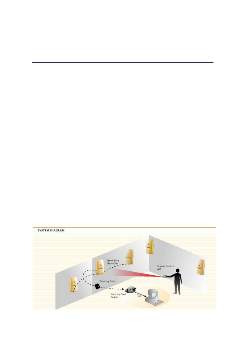
MemoCam stores all images in a Multimedia Card. To analyze
the recorded events on a PC, the Multimedia Card is removed
from the MemoCam unit and images are downloaded using a
Multimedia Card reader and the MemoCam software.
One or more stand-alone units can be placed at different
locations. The units are configured using the Multimedia Card.
The MemoCam is activated using the remote control unit.
Figure 1. The MemoCam System
¡ 1
Page 8

The MemoCam unit has the following features:
Automatic setup using the Multimedia Card.
User defined image quality, frame rate, and recording time
per event, delay between frames, and more.
Fixed or cyclic recording modes.
Pre-alarm recording.
Image integrity protection.
Arm/Disarm Scheduler.
Video motion detection (MemoCam Plus, DVR).
Multi camera support (MemoCam Plus, DVR).
Video out.
Remote Control unit.
Models and Features
This manual describes how to implement and install each of
the following MemoCam series models:
MemoCam — includes a CCD camera, a video
compression engine, a removable Multimedia Card, a
Passive Infrared (PIR) detector, and the option to connect
an external monitor and external alarm devices.
2 ¡
MemoCam Plus — provides additional features including
the option of connecting external cameras and external
PIRs and Video Motion Detection (VMD).
MemoCam DVR — designed for easy integration into
existing CCTV systems. MemoCam DVR does not contain a
camera or PIR, but supports up to three external cameras,
VMD, and video output capability.
MemoCam Plus/S* — like the MemoCam Plus but
provides the additional feature of a built-in serial port for
serial communication. “*” denotes “2” or “4”. The digit
represents the type of built-in serial communication port
featured by the model. MemoCam Plus/S2 and features an
RS-232 port. MemoCam Plus/S4 features an RS-485 port. A
series of MemoCam Plus/S4 units can all be connected to a
host.
Page 9

MemoCam DVR/S* — like the MemoCam DVR but
provides the additional feature of a built-in serial port for
serial communication. “*” denotes “2” or “4”. The digit
represents the type of built-in serial communication port
featured by the model. MemoCam DVR/S2 features an
RS-232 port. MemoCam DVR/S4 features an RS-485 port.
Table 1 shows a comparison of the main features of each
model in the MemoCam series.
¡ 3
Page 10

Table 1. MemoCam Models and Features
Function MemoCam
Input Interfaces 2 3(programmable) 3(programmable)
Programmable
Output Relay
Interface
PIR Detection
Output Relay
Interfaces
Internal B&W
Pin Hole Camera
Video Input
Interfaces
Video Output
Interface
Video Motion
Detection
Buzzer Yes Yes Yes
LEDs 3 3 3
Power Source EXT.
Tamper
Detection
Switch
External Control
Panel Input
Infra Red
Remote Control
Multimedia Card Yes Yes Yes
RS-485 port No Plus/S4 only DVR/S4 only
RS-232 port No Plus/S2 only DVR/S2 only
1 1 1
1 1 -
Yes Yes No
- 2 3
1 1 1
No Yes Yes
12V/500mA
DC
Yes Yes No
Yes Yes Yes
Yes Yes Yes
MemoCam Plus
and MemoCam
Plus/S*
EXT. 12V/500mA
DC
MemoCam DVR
and MemoCam
DVR/S*
EXT. 12V/400mA
DC
4 ¡
Page 11

Physical Description
The figures below show the physical components of the
MemoCam unit and remote control unit. Consult Table 2 to
see which figures are relevant to your model.
Table 2. Physical Description Figure Guide
Figure Description Models
2 Front View MemoCam,
MemoCam Plus,
MemoCam Plus/S*
3 Rear View MemoCam,
MemoCam Plus,
MemoCam Plus/S*
4 Front View MemoCam DVR,
MemoCam DVR/S*
5 Rear View MemoCam DVR,
MemoCam DVR/S*
6 Remote Control Unit All
Figure 2. MemoCam, MemoCam P us, MemoCam P us/S* Front Viewl l
¡ 5
Page 12
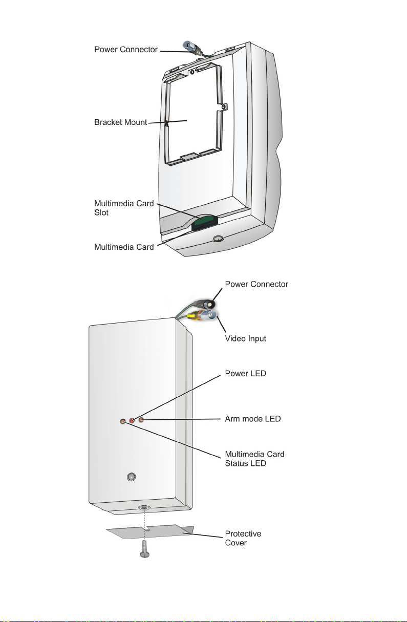
Figure 3. MemoCam, MemoCam Plus, MemoCam Plus/S* – Rear View
6 ¡
Figure 4. DVR, DVR/S* Front View
Page 13
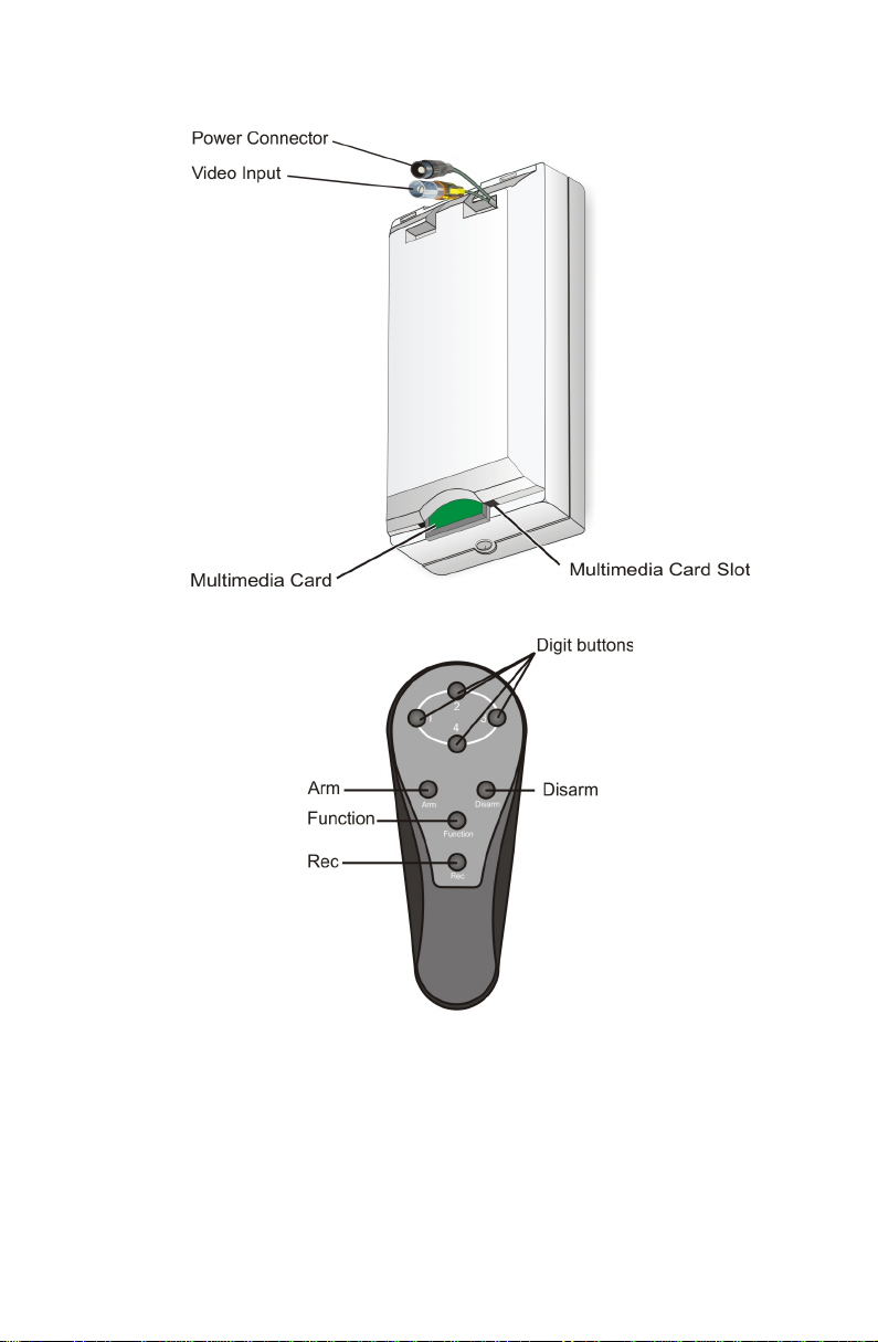
Figure 5. DVR, DVR/S* Rear View
Figure 6. Remote Control Unit
¡ 7
Page 14

Page 15

Installing the MemoCam® Unit
To install your MemoCam unit, follow this workflow:
1. Connect any external equipment you may want to use in
conjunction with the MemoCam. Refer to
Applications
2. Mount the unit on the wall, if necessary. Refer to
Mounting the MemoCam® Unit
3. Connect the power supply. Refer to
Supply
You will need:
on page 9.
on page 31.
on page 33.
MemoCam®
Connecting the Power
A screwdriver.
Two screws suitable for the type of wall.
You may also need a drill and two screw anchors.
MemoCam® Applications
MemoCam is a versatile security solution that supports many
different applications. You can connect your MemoCam unit
to various external devices, depending on your security needs.
This section includes the following:
Connecting External Equipment – describes a range of
possible MemoCam applications. Use this section to get an
idea of how you can maximize the use of your MemoCam.
Connecting an External Device – describes how to
connect any external device. Read this section before
connecting any external equipment.
MemoCam® Series Circuit Boards – describes the
interfaces and other key elements on the circuit board of
each model in the MemoCam series.
Connecting the Power Source – describes options for
connecting the MemoCam power source.
¡ 9
Page 16

Connecting External Cameras - describes how to connect
external cameras.
Connecting an External Monitor - describes how to
connect an external monitor.
Connecting an External Contact - describes how to
connect an external contact.
Connecting an Arm/Disarm Control - describes how to
connect an arm/disarm control.
Connecting a Light, Siren, or IR Illuminator - describes
how to connect a light, siren or IR illuminator.
Connecting Multiple MemoCam® Plus/S* or
MemoCam® DVR/S* Units to a Host - describes how to
connect one or more MemoCam Plus/S* or MemoCam
DVR/S* to a host.
Connecting External Equipment
The sections below describe various applications in which
MemoCam is integrated with other security devices.
Connecting External Cameras
Connecting to external cameras enables you to leverage the
surveillance features of the MemoCam solution for more than
one camera. External cameras allow for multiple angle
snapshots.
The MemoCam DVR and MemoCam DVR/S* models do not
contain internal cameras and are each designed to be used
with at least one external camera. One video input cable
comes pre-connected for this purpose.
The MemoCam Plus and MemoCam Plus/S* models also
support up to two external cameras. Figure 7 shows a
MemoCam Plus or MemoCam Plus/S* connected to two
external cameras.
10 ¡
Page 17
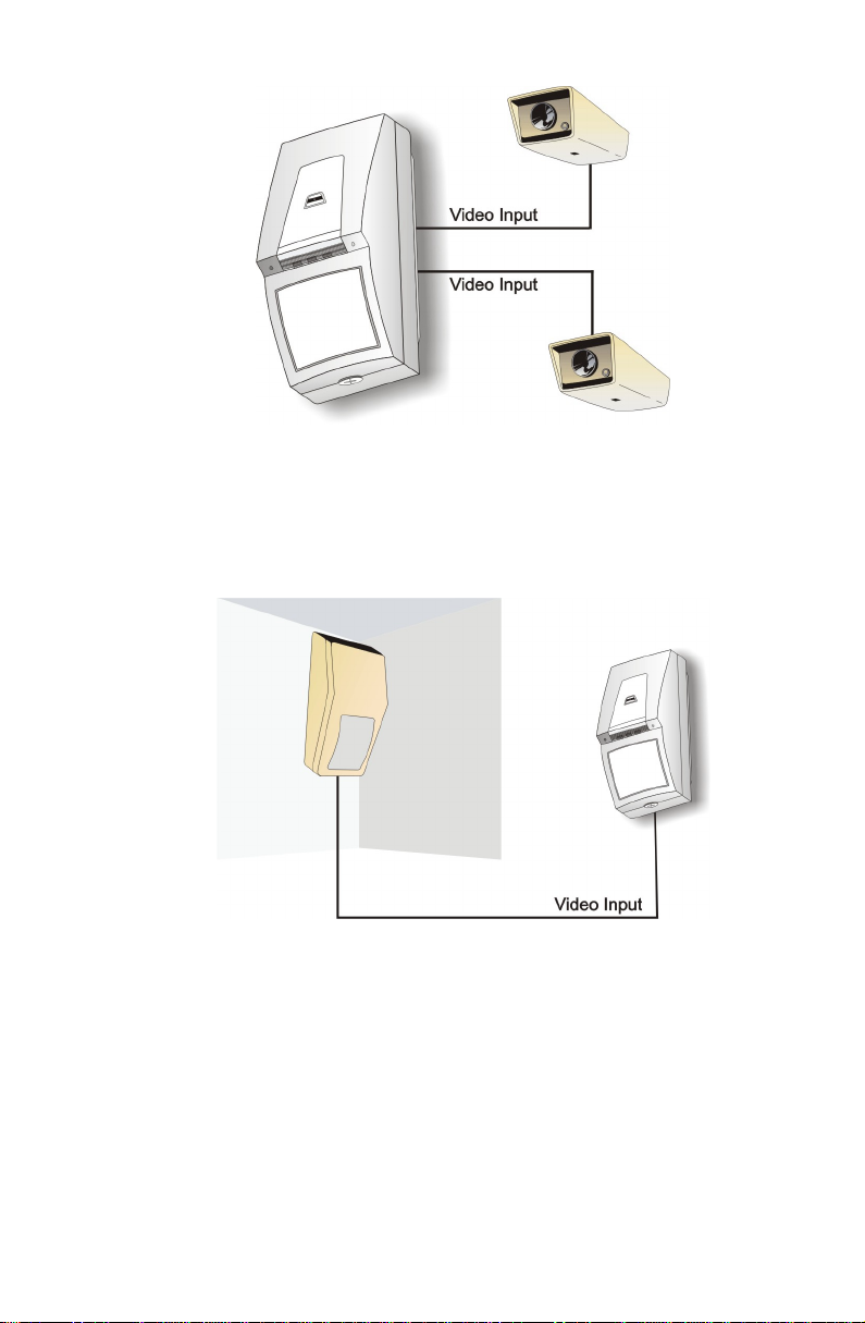
Figure 7. Using External Cameras
The DCAM 500 is a Video Domain camera that features a PIR
and a camera, ideal for taking snapshots from the same
position as the detection mechanism. Figure 8 shows the
MemoCam deployed in conjunction with a DCAM 500 camera.
Figure 8. Using the DCAM 500 as an External Camera
Communicating with a Host
The MemoCam Plus/S* and the MemoCam DVR/S* models
feature a serial communication port for connection to a host.
Figure 9 shows four MemoCam DVR/S* units communicating
with a host PC to connect and control a network of twelve
external cameras.
¡ 11
Page 18

Figure 9. Communicating with a Host
External Monitoring
All MemoCam models feature a video output interface for
external monitoring. Figure 10 shows a MemoCam connected
to an external monitor.
Figure 10. Using an External Monitor
Arming and Disarming MemoCam
You can control the arming and disarming of your MemoCam
in any of the following ways:
By remote control: you can arm or disarm the MemoCam
unit manually, using the remote control unit.
12 ¡
By external control: you can connect an on/off switch or
an alarm control panel to one of your MemoCam’s
programmable input interfaces (Figure 11).
Page 19
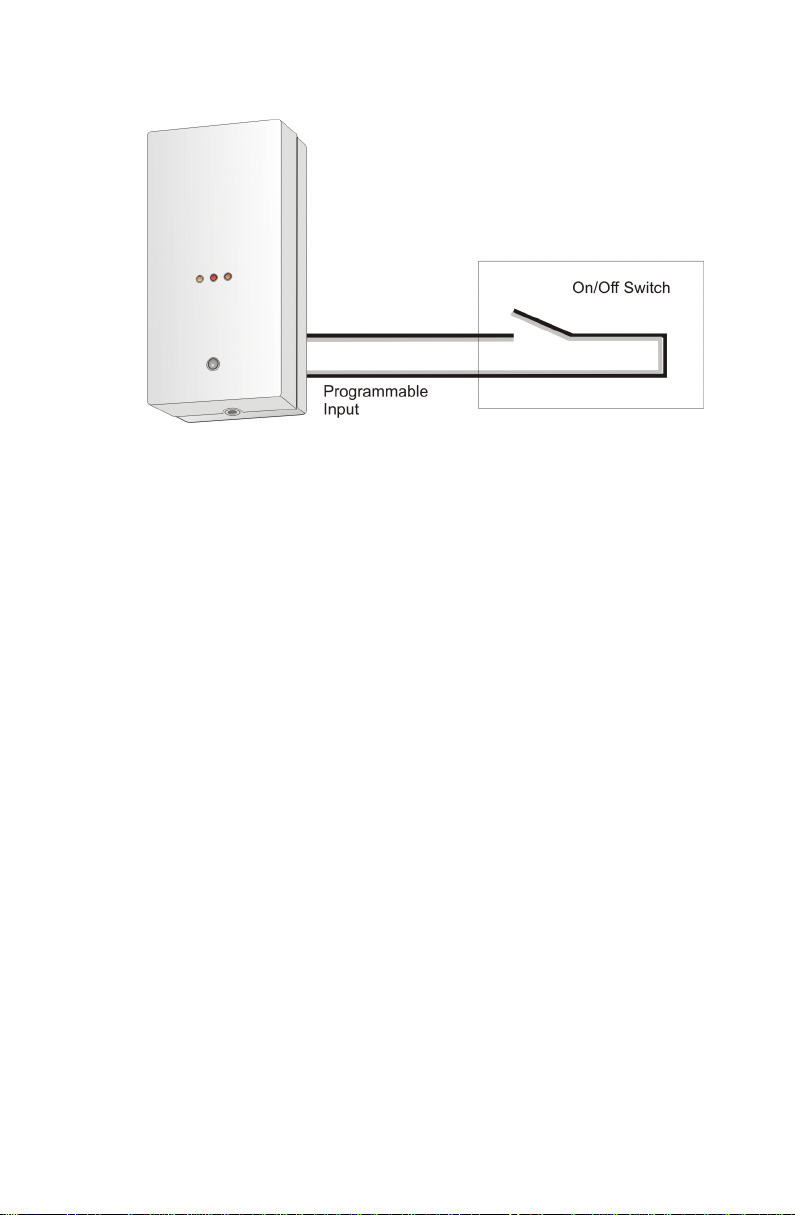
By internal schedule timing.
Figure 11. Arming and Disarming by External Control
Triggering Snapshots
Whether you are using MemoCam’s internal camera, or
connecting external cameras, there are various options for
controlling when snapshots are taken. Snapshots can be
triggered by:
The remote control unit. This lets you take a single
snapshot manually.
Internal Video Motion Detection (except MemoCam).
Internal PIR (except MemoCam DVR and MemoCam
DVR/S*).
An external trigger, such as a panic button or a magnetic
contact.
An external PIR.
¡ 13
Page 20
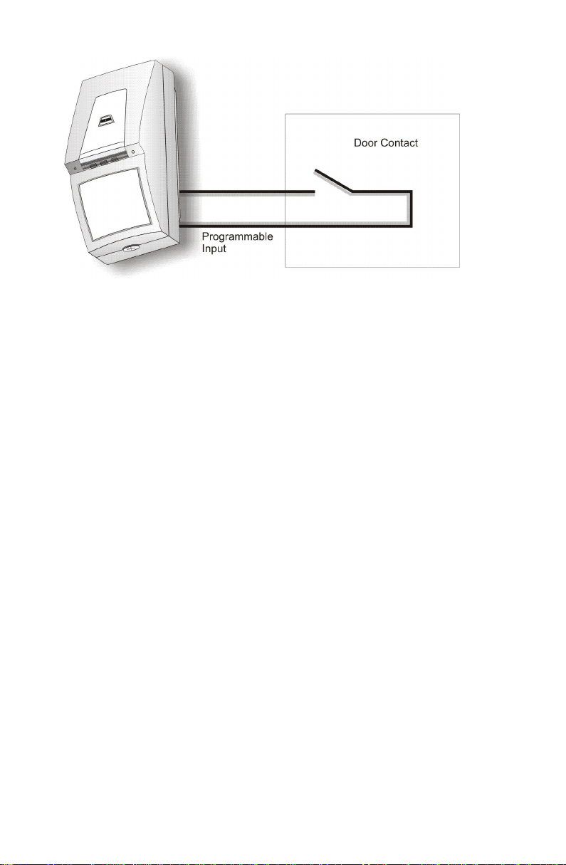
Figure 12. Triggering Snapshots with a Door Contact
Working in the Dark
If you will be configuring your MemoCam to take snapshots in
the dark, you will need to illuminate the space with a flash..
There are two ways of working in the dark:
Illuminating with a light bulb – The Memocam features
a programmable output relay (relay 2) to which you can
connect a step-up power relay that can feed a light bulb
from the mains (refer to Figure 13). You program the
output relay to turn on the light for the duration of the
recording event, normally several seconds.
Illuminating with an Infra-red LED illuminator – To save
power, you program the output relay to turn on the LED
illuminator only for the image grabbing time. The output
relay should be connected to a fast switch (12V, 2.5 A and
less than 2ms activation delay) that will feed the infra-red
LED illuminator (refer to Figure 14). Verify that the IR Flash
check box is selected in the MemoCam software
application (refer to the
MemoCam Software Manual
).
14 ¡
Page 21
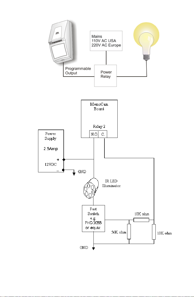
Figure 13. Switching on a Light when the Camera Takes a Snapshot
Figure 14. Activating an IR LED Illuminator
¡ 15
Page 22
The MemoCam software enables you to configure the output
relay interval appropriately for the device you connect.
Tamper Detection
The MemoCam unit features a tamper detection switch that
can be connected to an external device.
Sounding an Alarm
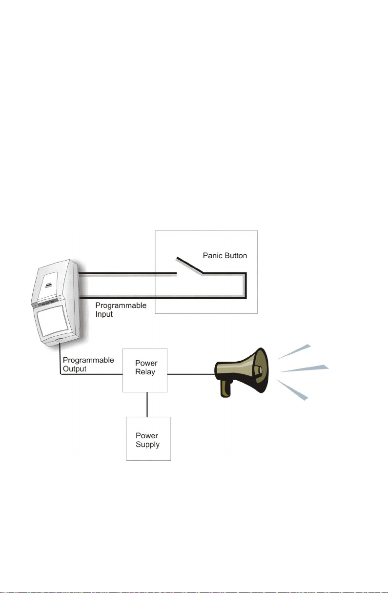
You can connect a MemoCam to a siren via the programmable
output relay. Figure 15 shows a MemoCam connected to a
siren and a panic button. In this example, the MemoCam can
be configured to sound the siren whenever the panic button is
pressed.
16 ¡
Figure 15. Triggering a Siren
Page 23
Connecting an External Device
You connect an external device by connecting each
component wire of the device’s connection cable to the
appropriate interface on your MemoCam unit’s circuit board.
To connect an external device to the MemoCam unit:
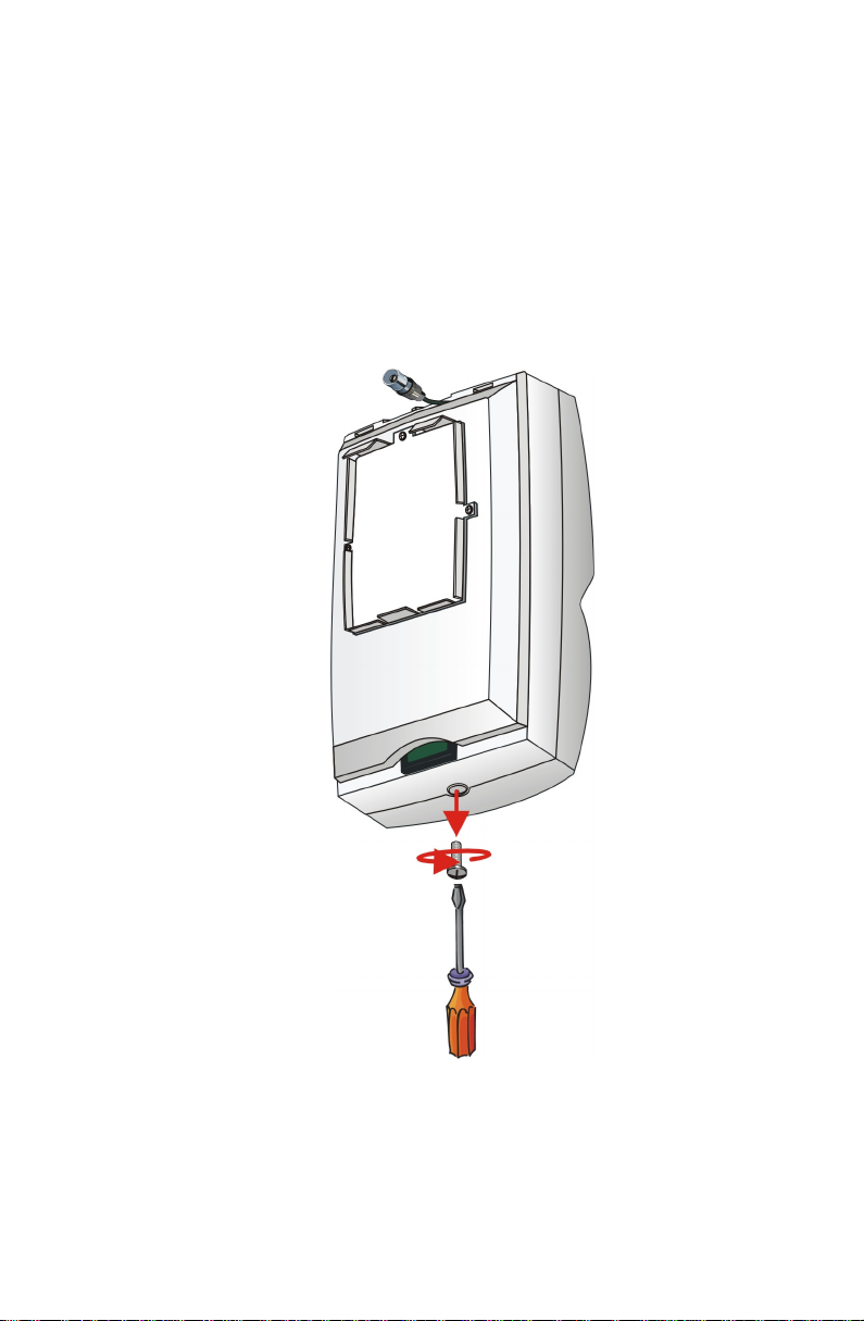
1. Open the MemoCam unit’s front cover by unscrewing the
holding screw on the bottom end of the device, as shown
in Figure 16.
Figure 16. Removing the MemoCam Front Cover
2. Knock out a hole in one of the locations marked in
Figure 17.
¡ 17
Page 24
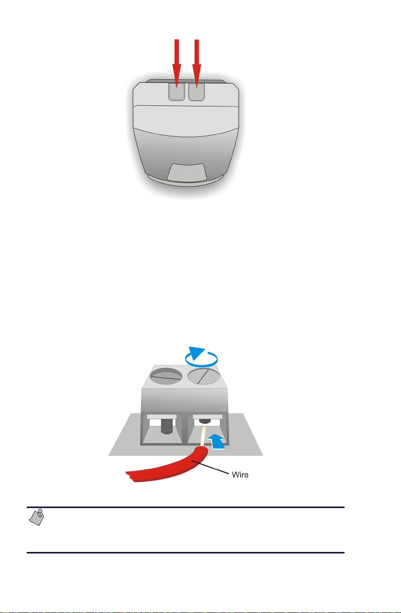
Figure 17. MemoCam Wire Access Knockout Holes
3. Thread the device’s connection cable through the hole.
4. Identify the correct interface to which to connect each
wire from the cable. For a description of all interfaces and
their general uses, refer to
Boards
specific device, refer to the sections below.
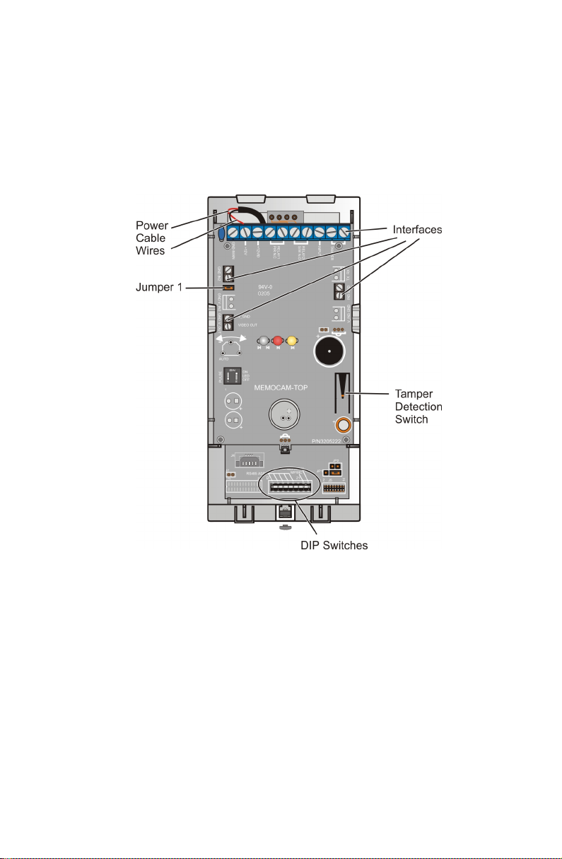
5. To connect each wire, unscrew the interface screw, insert
the wire into the hole below the screw, and tighten the
interface screw to secure the wire position (Figure 18).
on page 19. For instructions for connecting a
MemoCam® Series Circuit
Figure 18. Connecting the Wires
If you are connecting a backup power device, ensure that
jumper 1 on the circuit board is not connected. Refer to
Connecting the Power Source
18 ¡
on page 24.
Page 25
Reposition the unit’s cover and tighten the holding screw
(Figure 16).
MemoCam® Series Circuit Boards
Figure 19 shows key components of the MemoCam circuit
board.
Figure 19. MemoCam Circuit Board
Figures 20 to 24 show the interfaces for each MemoCam
model. Table 3 describes how each interface is used.
¡ 19
Page 26
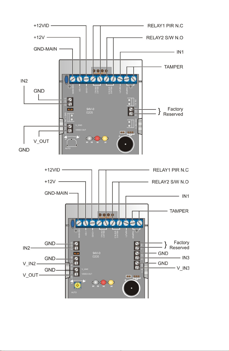
Figure 20. MemoCam Interfaces
Figure 21. MemoCam Plus Interfaces
20 ¡
Page 27
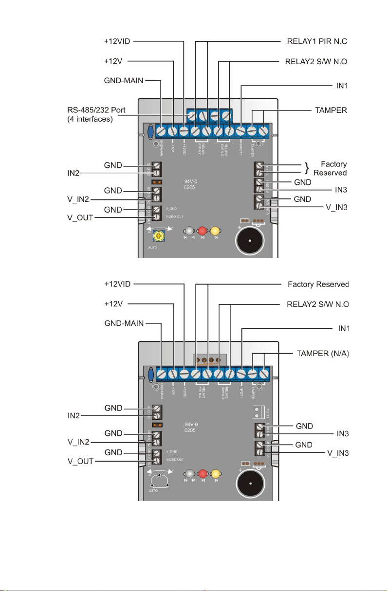
Figure 22. MemoCam P us/S* Interfaces l
Figure 23. MemoCam DVR Interfaces
¡ 21
Page 28
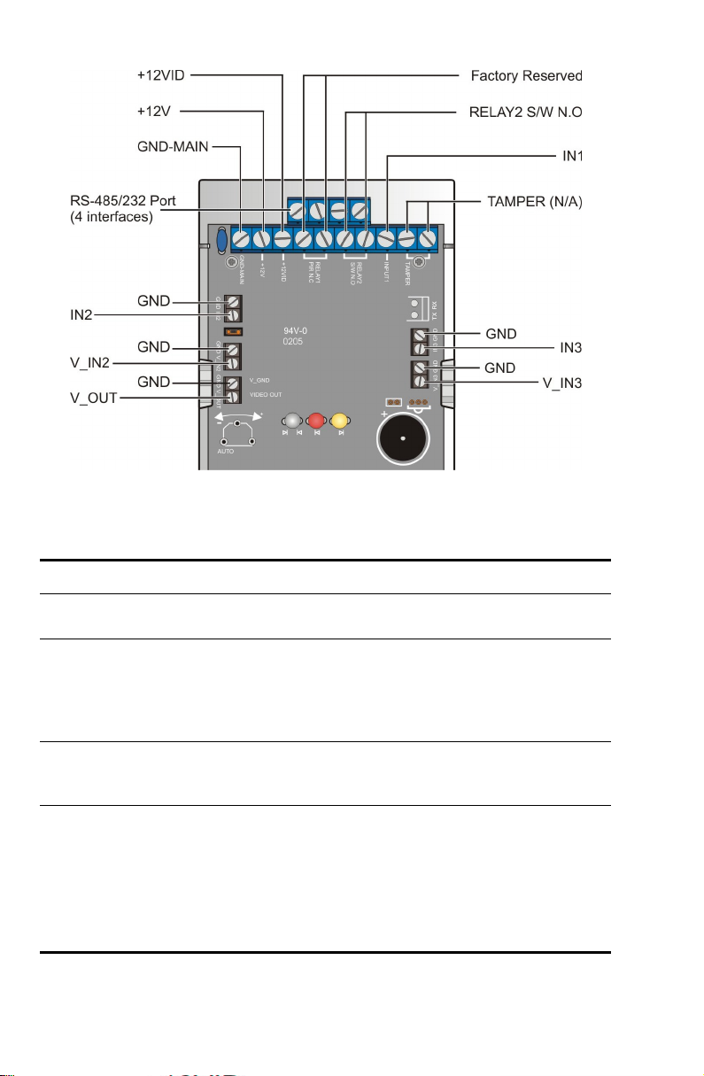
Figure 24. MemoCam DVR/S* Interfaces
Table 3. Circuit Board Interfaces
Interface Description Applicability
GNDMAIN
+12V
+12VID
RELAY 1
PIR N.C
22 ¡
Common power supply ground.
Connects to the positive output of
the ordinary power supply when
jumper 1 is installed or to the
backup power supply when jumper
1 is not installed.
Connects to the positive output of
a backup battery. Use only when
jumper is not installed (open).
PIR Detector Output Relay.
This relay is activated by the PIR,
and can be used to activate an
external alarm device. When
triggered by detected movement,
the relay N.C. contact opens for 1.6
seconds (standard).
Factory Reserved for
MemoCam DVR and
MemoCam DVR/S*.
Page 29

Interface Description Applicability
RELAY 2
S/W N.O
IN1 Programmable Input. (All models
TAMPER Tamper Detection Switch
IN2 and
GND
IN3 and
GND
Programmable Output Relay.
This relay is software-activated.
When tripped, the N.O. relay
contact closes for a pre-defined
period (0-999 s) that is user
selectable.
Used to switch on an external
device such as a video recorder,
light or siren.
except MemoCam)
Connects to an auxiliary device for
external alarm triggers or
arm/disarm control.
External Alarm Input. (MemoCam
only)
Connects to an auxiliary device for
external alarm triggers.
Use with GND-MAIN
The Tamper detection switch
terminals are N.C. contacts that
open when the MemoCam cover is
removed. They can be connected to
an external alarm or other device.
Programmable Input (All models
except MemoCam)
Connects to an auxiliary device for
external alarm triggers or
arm/disarm control.
Arm/Disarm Input. (MemoCam
only)
Connects to an auxiliary device,
such as control panel for
arm/disarm control.
Programmable Input.
Connects to an auxiliary device for
external alarm triggers or
arm/disarm control.
Not applicable for
MemoCam DVR and
MemoCam DVR/S*.
All models except
MemoCam.
¡ 23
Page 30

Interface Description Applicability
V_IN2
and
GND
V_IN3
and
GND
V_GND
and
VIDEO
OUT
RS485/232
Port
Video Input.
Connects to an external camera.
Video Input.
Connects to an external camera.
Video Output.
Connects to an external video
monitor.
Serial Communication Port.
Connects to a host.
All models except
MemoCam.
All models except
MemoCam.
MemoCam Plus/S* and
MemoCam DVR/S* only
Connecting the Power Source
The circuit board can be used to connect the MemoCam
power sources as follows:
Single Power Source – The MemoCam unit is powered by
a 12VDC, 500mA power supply that feeds both the PIR
and the video circuits. The MemoCam DVR is powered by
a 12 VDC, 400mA power supply.
Separated Power Sources – The MemoCam unit can be
connected to a normal power supply and a backup power
supply. In this configuration, when the normal power
supply is not available, the backup battery feeds only the
PIR, and thus can still activate an alarm. The MemoCam
cannot record images in backup power mode.
Jumper 1 on the circuit board (refer to Figure 19 on page 19)
is used as follows:
Installed (Default) – The MemoCam unit is powered by a
single DC power supply connected between GND MAIN
and +12V.
Not Installed – In this mode, the PIR module of the
MemoCam unit should be connected to a backup power
supply such as UPS or a battery from an alarm panel, in
addition to the main power supply. The backup power
supply is connected between GND MAIN and +12V,
24 ¡
Page 31

feeding the PIR, while the video circuits can be fed by an
ordinary power supply via GND MAIN and +12VID.
Connecting External Cameras
You can connect external cameras to any of the following
MemoCam models:
MemoCam Plus – up to two external cameras.
MemoCam Plus/S* – up to two external cameras.
MemoCam DVR – up to three external cameras.
MemoCam DVR/S* – up to three external cameras.
The MemoCam DVR and DVR/S* models each come with one
video input cable already connected, with an external
connector ready for connection to a camera (refer to Figure 4
on page 6).
You can use this video connector to connect one external
camera.
To connect a second or third external camera to a MemoCam
DVR or MemoCam DVR/S*, or to connect an external camera
to a MemoCam Plus or MemoCam Plus/S*:
Use one of the additional video input cables provided.
Connect the loose wires at one end of the cable to V_IN2
and GND or V_IN3 and GND.
Plug the external camera into the connector at the other
end of the cable.
The same video standard CCIR or EIA must be used for all
cameras (internal and external in MemoCam Plus, and all
external cameras in MemoCam DVR).
¡ 25
Page 32

Connecting an External Monitor
You can connect an external monitor to any MemoCam
model.
To connect an external monitor:
Use the Video Output cable provided.
Connect the open wires at one end of the cable to V_GND
and VIDEO OUT.
Plug the external monitor into the connector at the other
end of the cable.
Connecting an External Contact
You can connect an external contact, such as a magnetic door
contact, a panic button, or an External PIR, as a snapshot
trigger, to any model.
For all models except MemoCam, connect the contact directly
to one of the programmable input interfaces: IN1, IN2 or IN3
and one of the GND interfaces.
For MemoCam, connect the contact directly to IN1 and GND-
MAIN.
Connecting an Arm/Disarm Control
You can connect an arm/disarm control to any MemoCam
model either directly to an input interface, or to an input
interface via an alarm control panel.
For all MemoCam Plus and MemoCam DVR models, you can
designate only one programmable input interface as an
arm/disarm control. The programmable input interfaces are
marked IN1, IN2, and IN3 on the circuit board.
For MemoCam, IN2 is a fixed, non-programmable arm/disarm
input interface.
26 ¡
Page 33

Connecting a Light, Siren, or IR Illuminator
You can connect a light, siren, or IR illuminator to any model.
To connect a light, siren, or IR illuminator:
Connect the device via a power relay to the programmable
output relay interface, marked RELAY 2 S/W N.O on the
circuit board.
Connecting Multiple MemoCam® Plus/S* or
®
MemoCam
The MemoCam Plus/S* and the MemoCam DVR/S* support
serial communication with a host. This section describes how
to implement serial communication of one or more MemoCam
units to a host. For the MemoCam Plus/S4 or MemoCam
DVR/S4, refer to
For the MemoCam Plus/S2 or MemoCam DVR/S2, refer to
Setting up an RS-232 Connection
Setting up an RS-485 Connection
To set up an RS-485 connection:
DVR/S* Units to a Host
Setting up an RS-485 Connection
on page 30.
on page 27.
1. Allocate an RS-485 address to the MemoCam unit. Each
MemoCam on a parallel RS-485 line must be allocated a
different address. Refer to
on page 27.
2. Set the termination DIP switch. Refer to
Termination DIP
3. Wire the RS-485 interfaces. Refer to
Interfaces
4. Configure the host. Refer to
page 30.
Allocating an RS-485 Address
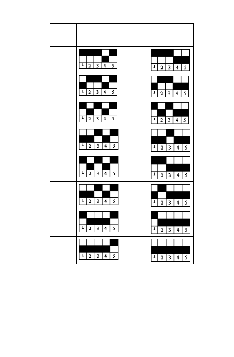
The RS-485 address range is 0-31. You can install up to 32
MemoCam Plus/S* units on the same line. On the
MemoCam
Plus/S* board, there are 5 DIP switches to define
switch on page 29.
on page 30.
Allocating an RS-485 Address
Setting the
Wiring the RS-485
Configuring the Host
on
¡ 27
Page 34
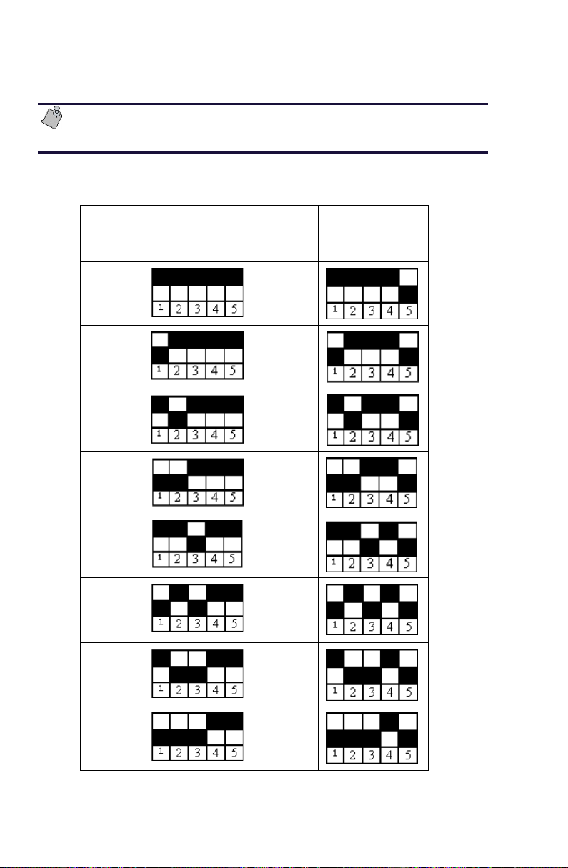
the RS-485 unit. Refer to Figure 19 on page 19 for the location
of the DIP switches.
Do not change the position of DIP switches 6 and 7. They
should always be in the down position.
The following table describes the DIP switch settings and the
corresponding RS-485 unit ID number assigned.
RS-485
unit ID
number
0
Factory
Default
1
2
3
4
5
RS-485 DIP
Switch
Settings
RS-485
unit ID
number
RS-485 DIP
Switch
Settings
16
17
18
19
20
21
28 ¡
6
7
22
23
Page 35
RS-485
unit ID
number
RS-485 DIP
Switch
Settings
RS-485
unit ID
number
RS-485 DIP
Switch
Settings
8
9
10
11
12
13
14
24
25
26
27
28
29
30
15
31
Setting the Termination DIP switch
DIP switch #8 is assigned for termination. If more than one
unit is installed on the same line, DIP switch #8 should be in
up
position in the last unit. In all other units, DIP switch
the
down
#8 should be in the
position. For a single unit installed
on the line, DIP switch #8 should be in the up position.
¡ 29
Page 36
Wiring the RS-485 Interfaces
The host device or each COM port on your PC must be
connected to the MemoCam unit’s RS-485 terminal connector
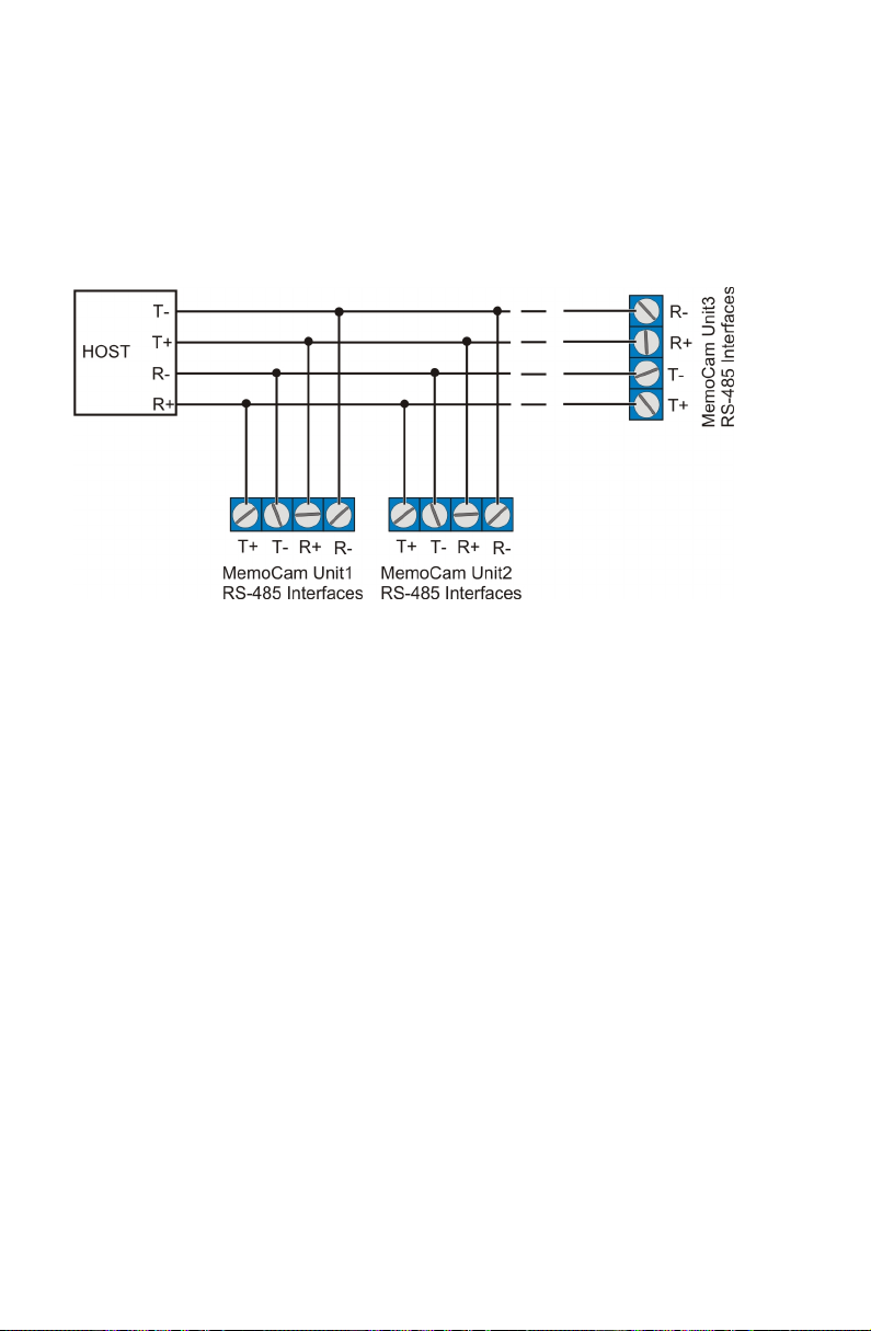
with four-wire cable in a
Figure 25 shows possible connections of three MemoCam
daisy chain
configuration.
units to a host device.
Figure 25. Connecting to a Host
Configuring the Host
Host RS-485 connection (or RS-485 converter) to your PC must
be configured with following parameters:
RS-485 full duplex.
RS-485 master.
No flow control.
The MemoCam software uses the following default settings
for networking parameters:
Baud rate: 115200
Parity: No parity
Stop bits: 1
Setting up an RS-232 Connection
The MemoCam Plus/S2 and MemoCam DVR/S2 units are
supplied with an RS-232 port instead of the RS-485 port on
the MemoCam Plus/S4 and MemoCam DVR/S4. When
30 ¡
Page 37
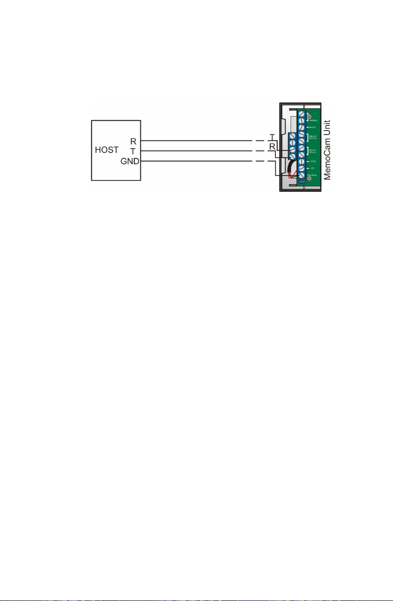
connecting a MemoCam Plus/S2 or MemoCam DVR/S2 to a
host, wire the connection as shown in Figure 26.
When working with an RS-232 connection, you can only
connect one MemoCam unit.
Figure 26. RS-232 Connections
Mounting the MemoCam® Unit
A MemoCam mounting bracket is included with the
MemoCam unit. It is not necessary to mount MemoCam DVR
and DVR/S* models, since they do not contain an internal
camera or PIR.
Begin by selecting a mounting location on the wall. Choose a
location most likely to intercept an intruder. Make sure that
the MemoCam unit’s power cord can reach a nearby power
receptacle. If necessary, an extension cord can be used.
The PIR is most sensitive in detecting sideways motion.
The MemoCam unit performs best in steady light and stable
temperature.
Avoid the following locations:
Facing direct sunlight or light sources.
Facing areas subject to quick temperature changes.
Areas with air ducts or substantial air flows.
Facing areas with high light contrast.
¡ 31
Page 38
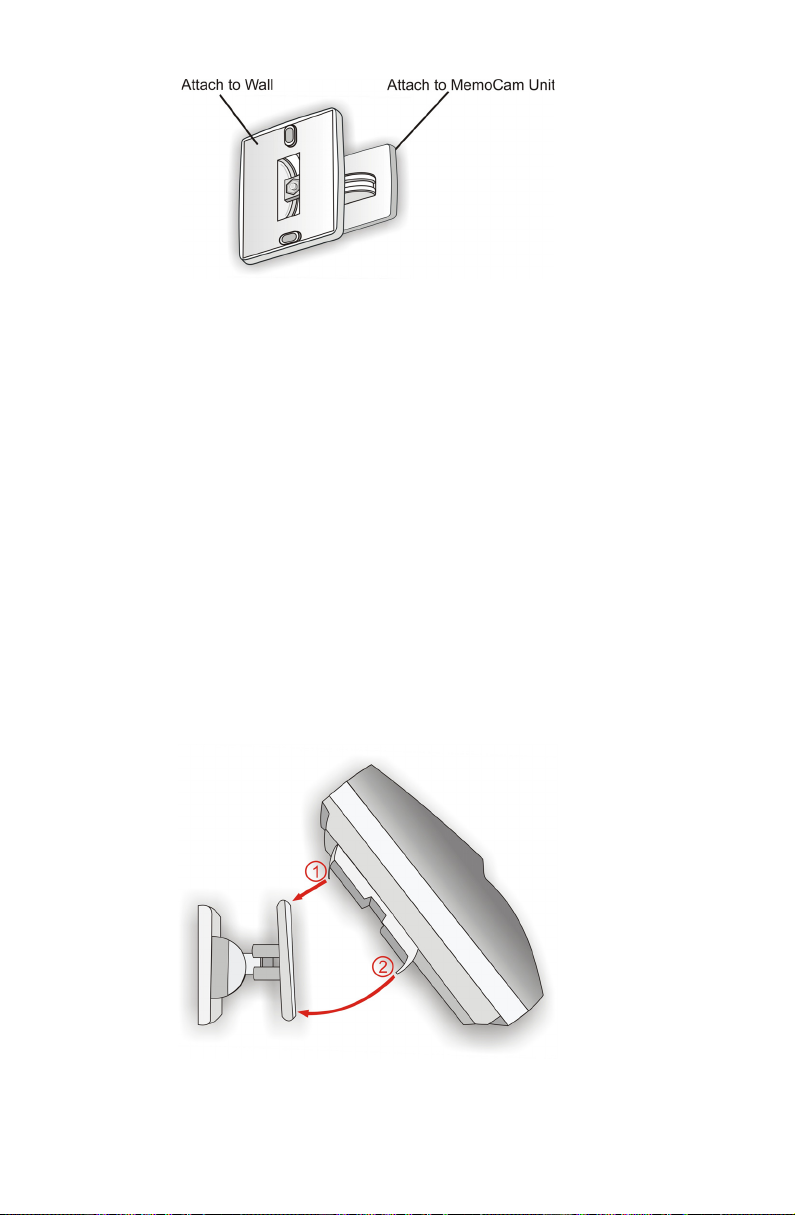
Figure 27. Mounting Bracket
To mount the MemoCam unit:
1. Loosen the two pieces of the mounting bracket without
separating them. The two sections of the bracket should
swing freely.
2. Place the wall-mount section of the bracket (refer to
Figure 27) on the desired location on the wall, and mark
the drill points through the two fastener holes.
3. Drill the holes (if necessary) and attach the bracket to the
wall with screws.
4. Retighten the two mounting bracket pieces so that the
MemoCam Mount section can still be rotated with slight
pressure.
5. Clip the upper part of the MemoCam unit’s holder (1) to
the bracket and rotate, as indicated in Figure 28, until the
MemoCam unit snaps into place (2).
32 ¡
Figure 28. Mounting the MemoCam Unit
Page 39

6. Adjust the position of the MemoCam unit by moving it
slowly up/down and left/right to the desired position.
7. Remove the MemoCam unit carefully from the bracket
without changing the bracket position.
8. Tightly screw the two mounting bracket pieces.
9. Re-attach the MemoCam unit to the bracket as indicated
in step 5 above.
10. For robust fixture, twist slightly part 2 of bracket mount
with pliers (refer to Figure 28).
Connecting the Power Supply
Connect the power adapter to the power connector coming
out of the MemoCam unit. Refer to
page 5 to identify the power connector on your model.
Plug the power supply unit into a wall socket. The MemoCam
status LED indicators illuminate (refer to Table 4 on page 36
for details).
The MemoCam unit works only with the original, supplied,
power adaptor.
Physical Description
on
¡ 33
Page 40

Page 41

Operating the MemoCam®
Once the MemoCam unit is installed, the unit operates
according to a default configuration. You can change the
configuration using the Multimedia Card. Refer to
the MemoCam®
on page 41 for configuration information.
Understanding LED Indicators and Audible Signals
The MemoCam unit indicates activities and errors via LED
indicators on the front panel and by emitting audible signals.
LED Indicators
The MemoCam unit has three LED status indicators.
The LED indicators are located on the front of the MemoCam
unit. Refer to
of each model. Table 4 describes the possible LED indications.
Physical Description
on page 5 for the front view
Configuring
¡ 35
Page 42

Table 4. LED Indications
LED Color Description
Left
(Multimedia Card Status)
Blinking
Orange Multimedia Card is full
Middle
(For MemoCam,
MemoCam Plus, and
MemoCam Plus/S*: PIR
Activation)
(For MemoCam DVR and
MemoCam DVR/S*: Power
Indication)
Right
(Arm Mode)
Red Multimedia Card is faulty or not
inserted correctly
Data is being written to the
Green
Flashing
Red
Red Power is connected
Orange
None
Multimedia Card
Movement detected
ARM mode
DISARM mode
Audible Signals
The MemoCam emits the following audible signals when you
use the remote control unit to perform the following actions:
Arm the unit – Long beep.
Enter a disarm code – Short beep after each button is
pressed.
Disarm the unit – Two short beeps and one long beep.
The MemoCam emits the following signals in the following
scenarios:
In Disarm mode – a recurring short beep.
The Multimedia Card is not inserted – a recurring short
beep.
The configuration is upgraded by inserting a Multimedia
Card carrying an upgraded configuration – one short
beep.
The registry becomes corrupted and the MemoCam unit
returns to default configuration – three short beeps.
36 ¡
Page 43

Performing Remote Control Operations
You can use the remote control unit provided with the
MemoCam to:
Arm the MemoCam
Disarm the MemoCam
Record a snapshot
Control the video output
Using the Remote Control
You can use the remote control unit provided with your
MemoCam to arm, disarm, and record snapshots. You can also
use the remote control unit to control the image displayed on
a connected video monitor for MemoCam Plus and DVR.
The remote control unit has the following buttons (refer to
Figure 6 on page 7):
Rec – Triggers a snapshot to be taken.
Arm – Activates the MemoCam for operation.
Disarm – Deactivates the MemoCam.
Function – Not in use.
Four digit buttons numbered 1, 2, 3, 4 – Allows for Disarm
Code entry. Selects from multiple cameras in MemoCam
Plus and MemoCam DVR only.
Insert batteries into the Remote Control unit before use.
Arming the MemoCam®
To arm the MemoCam using the remote control unit:
1. Make sure the MemoCam unit is powered, and the
Multimedia Card is inserted.
2. Point the remote control unit at the MemoCam and press
Arm
the
Arm Mode (right) LED illuminates orange to inform you
that the unit is armed.
button. The MemoCam unit beeps once and the
¡ 37
Page 44

A user-defined exit delay allows you several seconds to exit the
room before the MemoCam detector arms the system.
You can also automatically arm the MemoCam unit upon
Multimedia Card insertion, or schedule MemoCam to arm
itself at particular times. Refer to the
Manual
for details.
MemoCam Software
Disarming the MemoCam®
To disarm the MemoCam using the remote control unit:
1. Point the Remote Control unit at the MemoCam and enter
the Disarm Code using the four digit buttons. To define a
Disarm Code, refer to the
2. Press the
times and the Arm Mode (right) LED turns off to inform
you that the unit is disarmed.
You have a few seconds to enter the room before the
MemoCam detector records an image in the system. Refer to
MemoCam Software Manual
the
define the Entry Delay.
Disarm
button. The MemoCam unit beeps three
MemoCam Software Manual
for information on how to
.
Recording a Snapshot
You can use the remote control to record a snapshot at any
given moment.
To record a snapshot using the remote control unit:
1. Make sure that the MemoCam is in disarm mode, and the
Multimedia Card is inserted.
2. Point the Remote Control unit at the MemoCam and press
Rec
the
blinks green informing you that an image is being
recorded.
The Snapshot function should also be used to check the
MemoCam after initial installation.
In MemoCam Plus and DVR, all connected cameras record
snapshots according to the configuration programmed with
the software.
38 ¡
button. The Multimedia Card Status (left) LED
Page 45

Controlling the Video Output
This function is available in all models except the MemoCam
model. It is available only when the unit is in Disarm mode.
The Video Output function can be used for fine adjustment of
the MemoCam unit’s position while in disarm mode, and for
live video monitoring.
Use the numbered buttons on the remote control unit to
select which camera’s image is displayed on the video monitor
as follows:
Button 1 – Displays the image from Camera 1.
Button 2 – Displays the image from Camera 2.
Button 3 – Displays the image from Camera 3.
Button 4 – Cycles the image between all selected cameras.
Refer to the
MemoCam Software Manual
for details.
¡ 39
Page 46

Page 47

Configuring the MemoCam®
The MemoCam has default configuration settings that allow
for immediate use upon initial installation.
You can also customize the MemoCam configuration using the
Multimedia Card and MemoCam software provided with your
MemoCam Unit.
Using the Multimedia Card
To use the Multimedia Card to configure your MemoCam, you
will need:
A PC, with the MemoCam software installed.
An off-the-shelf Multimedia Card reader.
Formatting the Multimedia Card
Before you can use the Multimedia Card to configure your
MemoCam unit, you must format the card.
To format the card:
1. Ensure that the MemoCam unit is powered.
2. If the protective cover is covering the Multimedia Card
slot, remove the protective cover from the Multimedia
Card slot.
3. Insert the Multimedia Card into the card slot on the
bottom of the MemoCam unit, as shown in Figure 29.
Lock the card securely into the slot.
¡ 41
Page 48
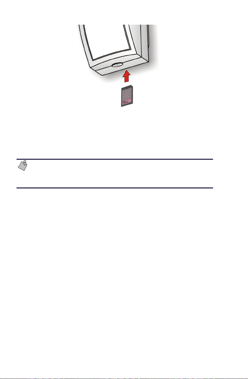
Figure 29. Inserting the Multimedia Card
4. Wait until the Multimedia Card Status (left) LED turns off.
5. Gently push the Multimedia Card further into the card slot
and release your finger. The card is unlocked from the slot
and removable.
The MemoCam must be in disarm mode before you remove
the Multimedia card. Refer to
38
page
.
Disarming the MemoCam®
on
Changing the Configuration Settings on the Multimedia Card
To configure the MemoCam unit:
1. Connect your Multimedia Card reader to the USB port of
your PC.
2. Insert the Multimedia Card into the card reader.
3. Use the MemoCam software to set the configuration
parameters on the Multimedia Card. Refer to the
MemoCam Software Manual
to use the software.
for information about how
Updating the Configuration of the
®
MemoCam
When you have changed the configuration settings on the
Multimedia Card using the MemoCam software, you update
the configuration of the MemoCam unit by inserting the
42 ¡
Unit
Page 49

Multimedia Card into the card slot on the bottom of the
MemoCam unit, as shown in Figure 29. Lock the card securely
into the slot. If the configuration on the card is different from
the previous configuration of the MemoCam unit, the unit
beeps. The configuration is automatically updated.
For detailed configuration information, refer to the
Software Manual
.
MemoCam
The MemoCam unit has an internal clock. To configure the
date and time, refer to the
MemoCam Software Manual
.
¡ 43
Page 50

Page 51

Testing the Installation
Testing System Functionality
To check that MemoCam was installed successfully and is
operational:
1. Make sure the Multimedia Card is inserted in the
MemoCam unit (refer to Figure 29 on page 42).
2. Disarm the MemoCam (refer to
MemoCam®
3. Point the remote control unit at the MemoCam unit and
press Rec. The Multimedia Card Status (left) LED blinks
green.
4. Remove the Multimedia Card from the MemoCam by
gently pushing the Multimedia Card further into the card
slot and releasing your finger.
5. Insert the Multimedia Card into the Multimedia Card
reader attached to your computer or Pocket PC.
6. View the images using the MemoCam software. Refer to
MemoCam Software Manual
the
using the software.
on page 38).
Disarming the
for information about
Troubleshooting
Use the following table to troubleshoot your MemoCam.
Should you require further assistance or support in using your
MemoCam, contact your local dealer.
Problem Symptom Solution
Unit does not
work.
Impossible to operate
unit, left LED does not
glow, and PIR LED
does not blink.
Check power supply and
power cable.
¡ 45
Page 52

Problem Symptom Solution
The MemoCam
unit does not
record even though
a Multimedia Card
is inserted in the
unit.
Remote control
does not work.
Cannot arm unit
using remote
control.
Cannot disarm unit
using remote
control.
Cannot record an
image using the
remote control
unit.
MemoCam
application does
not correctly read
the Multimedia
Card.
Left red LED remains
illuminated when
Multimedia Card is
inserted into the unit.
The unit does not
recognize the
Multimedia Card.
Unit does not arm
and other remote
control functions do
not work. No
beeping.
Unit may already be armed.
Unit may already be
Ensure that the unit is
You receive error
messages.
1. Remove the Multimedia
Card from the
MemoCam unit.
2. Re-power the
MemoCam unit.
3. Insert the card back into
the MemoCam unit.
After a few seconds, the
left red LED should go
off.
4. Arm the unit and make
sure the left LED flashes
green when new images
are recorded on the
Multimedia Card.
Check remote control
batteries.
Try to disarm the unit first.
disarmed, or you may not be
disarming the unit properly.
Enter the disarm code and
then click the disarm button.
Check that the code is
correct.
disarmed – You cannot use
snapshot recording when
system is armed.
Check that the Multimedia
Card is inserted correctly into
reader.
Try restarting the MemoCam
application.
46 ¡
Page 53

Problem Symptom Solution
MemoCam
application does
not start correctly.
You receive error
messages while
working with
MemoCam
application.
Reader is not
installed as
additional drive.
Image is black The Multimedia Card
Check that you installed the
Restart the application.
You see the
Multimedia Card as A:
or B: drive.
MemoCam
Application works in
demo mode.
player displays a black
picture.
application as described in
the manual. If not, reinstall
the application.
Edit the memocam.ini file to
force the reader drive as
follows:
[Source]
MMC-Source=a:\
Check the video cable
connecting the unit to the
camera.
Check that the camera is
powered and the lens is
unobstructed.
¡ 47
Page 54

Page 55

Technical Specifications
Following are the specifications for the various MemoCam systems.
Dimensions
External dimensions
W x H x D
(excluding base)
Weight (excluding base) MemoCam, MemoCam Plus, MemoCam
MemoCam, MemoCam Plus, MemoCam
Plus/S*:
66 x 135 x 56 mm
MemoCam DVR, MemoCam DVR/S*:
66 x 135 x 36 mm
Plus/S*:
220 g
MemoCam DVR, MemoCam DVR/S*:
280 g
Camera
For MemoCam, MemoCam Plus, and MemoCam Plus/S* only.
TV standard B&W, CCIR, or EIA
Resolution 420 TV lines
Sensitivity 0.1 Lux (F2.0)
S/N Ratio Better than 48db
Shutter control Automatic 1/50 - 1/100,000
Pinhole lens F4.3 mm standard
Multimedia Card Reader
Recording Capacity (number of images)
Card Size
8 MB 350 700 1400
16 MB 750 1500 3000
Highest Quality:
20 KB per frame
Average Quality:
10 KB per frame
Lowest Quality:
5 KB per frame
¡ 49
Page 56

Recording Capacity (number of images)
Card Size
32 MB 1500 3000 6000
64 MB 3000 6000 12000
128 MB 6000 12000 24000
Highest Quality:
20 KB per frame
Average Quality:
10 KB per frame
Lowest Quality:
5 KB per frame
Picture Format and Recording
Picture format JPEG with automatic Thumbnails
Support.
Picture quality options From 5K up to 20K image sizes.
Recording rates From 3 images per second to 1 image
per 5 minutes.
Recording options
Delay time between alarm triggers 1 to 999 seconds
Number of images per event 1 to 101 images
Fixed – Records fixed number of
events or until memory is full.
Cyclic – When Multimedia Card is full,
continues recording over oldest
events.
Infrared Motion Detector – Dual Element PIR
For MemoCam, MemoCam Plus, and MemoCam Plus/S* only.
Lens Type Hard Spherical Lens
Sensitivity U 1.6 oC (U 3oF)@0.6 m/sec (2 ft/sec)
Detection Speed 0.3-1.5 m/sec (1-5 ft/sec)
Temp. compens. Bi-directional
Pulse count 1,2 DIP switch; 2-3 Automatic depending on
speed spectrum analysis.
Coverage Wide angle 90º 18m x 18m
(60ft x 60ft)
RFI Protection 30V/m 10-1000 MHz
EMI Protection 50,000V of electric interference from lightning
or power through.
50 ¡
Page 57

Interfaces and Switches
PIR Detector Output Relay 350VDC, 0.1A with 30 ohm serial resistance.
Normally closed, opens for 1.6 sec upon
detection.
Programmable Output
Relay
Programmable Input Isolated dry contact input.
Tamper Detection Switch If cover is removed.
Separated power feeds Optional Separated power feeds for PIR and
Video Input 1V PP, CCIR or EIA
Video Output 1V PP, CCIR or EIA
350VDC, 0.1A with 30 ohm serial resistance.
Normally open, closes from 0 to 999 sec.
Recording module sections.
Power Supply
Total power consumption Maximum – 500 mA @ 12 VDC
PIR detector only Typical – 30 mA @ 12 VDC
MemoCam DVR Typical – 400 mA @ 12 VDC
System Requirements
The following are the minimum system requirements for
installing the MemoCam viewer application on a PC, or the
Pocket PC viewer application on a pocket PC.
PC Minimum Requirements
CPU Pentium II 200 Mhz or higher.
RAM 16 MB or higher.
Graphic adapter Super VGA or higher.
Display resolution 640x480, 16 bit or higher.
Operating systems Windows 95, 98, 2000, ME, NT, or XP
with Internet Explorer
Multimedia Card
reader
TM
5.0 or higher.
¡ 51
Page 58

Pocket PC Minimum Requirements
CPU ARM (or compatible)
RAM 16 MB or higher
Display resolution 320x240, 16 bit or higher
Operating systems Windows CE 3.0 or higher
Multimedia Card reader
52 ¡
Page 59

Glossary
Arm Enables automatic detection and recording
function.
Cyclic Recording Continuous recording. The MemoCam
records over older images from start of the
cycle when Multimedia Card is full.
Disarm Disables the automatic detection and
recording function.
Entry Delay Time between first trigger and actual
recording (unit is armed).
Entry delay can be used when entering a
room to avoid event recording until the
unit is disarmed.
Event The recording of one or more images as a
result of a trigger.
Exit Delay Once the operator arms the unit, a delay
can be used to avoid event recording when
exiting the room.
LED Light Emitting Diode. An electric
component that lights up.
Multimedia Card A stamp-sized plastic card containing
read/write non-volatile memory.
PIR Passive Infrared motion detector.
Snapshot Recording of a single picture.
Trigger A signal that activates the recording
process. Usually generated by an alarm
contact.
VMD Video Motion Detection. A feature that
detects changes in video frames.
¡ 53
 Loading...