

Victron energy Phoenix 12/800, Phoenix 24/800, Phoenix 48/800, Phoenix 12/1200, Phoenix 24/1200 Instruction Manual
...
Manual
EN
Handleiding
NL
Manuel
FR
Anleitung
DE
Manual
ES
Appendix
Phoenix Inverter
12 | 800 12 | 1200
24 | 800 24 | 1200
48 | 800 48 | 1200


Copyrights 2008 Victron Energy B.V.
All Rights Reserved
This publication or parts thereof, may not be reproduced in any form, by any method,
for any purpose.
For conditions of use and permission to use this manual for publication in other than
the English language, contact Victron Energy B.V.
VICTRON ENERGY B.V. MAKES NO WARRANTY, EITHER EXPESSED OR
IMPLIED, INCLUDING BUT NOT LIMITED TO ANY IMPLIED WARRANTIES OF
MERCHANTABILITY OR FITNESS FOR A PARTICULAR PURPOSE, REGARDING
THESE VICTRON ENERGY PRODUCTS AND MAKES SUCH VICTRON ENERGY
PRODUCTS AVAILABLE SOLELY ON AN “AS IS” BASIS.
IN NO EVENT SHALL VICTRON ENERGY B.V. BE LIABLE TO ANYONE FOR
SPECIAL, COLLATERAL, INCIDENTAL, OR CONSEQUENTIAL DAMAGES IN
CONNECTION WITH OR ARISING OUT OF PURCHASE OR USE OF THESE
VICTRON ENERGY PRODUCTS. THE SOLE AND EXCLUSIVE LIABILITY TO
VICTRON ENERGY B.V., REGARDLESS OF THE FORM OF ACTION, SHALL NOT
EXCEED THE PURCHASE PRICE OF THE VICTRON ENERGY PRODUCTS
DESCRIBED HERE IN.
Victron Energy B.V. reserves the right to revise and improve its products as it sees fit.
This publication describes the state of this product at the time of its publication and
may not reflect the product at all times in the future


1
EN NL FR DE ES Appendix
1. Installation
1.1 General
WARNING: ELECTRIC SHOCK HAZARD
The product is used in conjunction with a permanent energy source (battery). Input
and/or output terminals may still be dangerously energized, even when the equipment
is switched off. Always disconnect the battery before carrying out maintenance or
servicing the product.
The product has no internal user-serviceable components. Do not remove the front
plate or operate the product if any panels have been removed. All servicing must be
undertaken by qualified personnel.
Please read the installation instructions in the installation manual before installing the
equipment.
This is a Safety Class I product (supplied with a protective grounding terminal). The
chassis must be grounded. A grounding point is located on the outside of the product.
Whenever it is likely that the grounding protection has been damaged, the product
must be turned off and secured against unintended operation; please contact qualified
service staff.
The AC output is isolated from the DC input and the chassis. Local regulations may
require a true neutral. In this case one of the AC output wires must be connected to
the chassis, and the chassis must be connected to a reliable ground, see figure
1. Please note that a true neutral is needed to ensure correct operation of an earth
leakage circuit breaker.
Ensure that the equipment is used under the correct ambient conditions.
Never operate the product in a wet or dusty environment.
Never use the product where there is a risk of gas or dust explosions.
Ensure there is adequate free space (10 cm) for ventilation around the product and
check that the ventilation vents are not blocked.
1.2 Connection to the battery
The inverters are equipped with two DC connection cables with a length of 1.5
meters. If it is unavoidable to extend these cables, use a wire gauge of at least 2
times larger than the ones supplied with the inverter. Maximum recommended battery
wire length is 5 meters.
The inverters are fitted with an internal DC fuse (see technical data). If the DC cable
length is increased to more than 1,5 m, an additional fuse or DC circuit breaker must
be inserted close to the battery.
The red wire must be connected to the positive (+) terminal and the black wire
to the negative (-) terminal of the battery.
Reverse polarity connection of the battery wires will blow the internal fuse and can
damage the inverter.

2
1.3 Connecting the load
Some loads like motors or pumps draw large inrush currents in a start-up situation. In
such circumstances, it is possible that the start-up current exceeds the over current
trip level of the inverter. In this case the output voltage will quickly decrease to limit
the output current of the inverter. If the over current trip level is continuously
exceeded, the inverter will shut down and restart. If an overload occurs 3 times
within 30 seconds the inverter will shutdown. To restart the inverter: switch the
Inverter “off”, wait 2 seconds and switch the Inverter “on”.
Never connect the output of the inverter to another AC source, such as a
household AC wall outlet or a generator.
1.4 Search Mode
If search mode is ‘on’, the power consumption in no-load operation is decreased by
approx. 70%. In this mode the inverter is switched off in case of no load or very low
load, and switches on every two seconds for a short period. If the output current
exceeds a set level, the inverter will continue to operate. If not, the inverter will shut
down again.
The standard settings are:
Shut down: 20 Watt (linear load)
Turn on: 30 Watt (linear load)

3
EN NL FR DE ES Appendix
2. Troubleshooting
Flash sequence table
LED
Status
Solution
Solid green
Red off
Normal operation
Green blinking
slow
Red off
Search mode active If a load is connected, and the
inverter does keep switching on
and off, the load may be too small:
increase load.
Green off
Red off
Inverter off Check the switch on the inverter:
should be in on position or in
search mode position.
Check remote switch connection.
Check DC cable connections.
Inverter fuse blown: the inverter
has to be returned for service.
Green off
Red blinking
fast
− − − − − − − −
Over voltage Reduce DC input voltage.
Solid green
Solid red
Imminent shut down due to
overload
Reduce load.
Green off
Solid red
Overload Reduce load.
Switch the Inverter off, wait 2
seconds and switch the Inverter
on.
Solid green
Red blinking
slow
Imminent shut down due to
under voltage
Recharge or replace battery.
Check DC cable connections.
In case of long DC cables: cable
cross section may be insufficient.
Green off
Red blinking
slow
Under voltage Recharge or replace battery.
See Technical Data for restart
voltage.
Solid green
Red blinking
intermittently
−
−−
− −−−− −−−− −−−− −−−− −−−−
Imminent shut down due to
over temperature
Reduce load.
Green off
Red blinking
intermittently
−
−−
− −−−− −−−− −−−− −−−− −−−−
Over temperature Wait for the inverter to cool down
and reduce load.
4
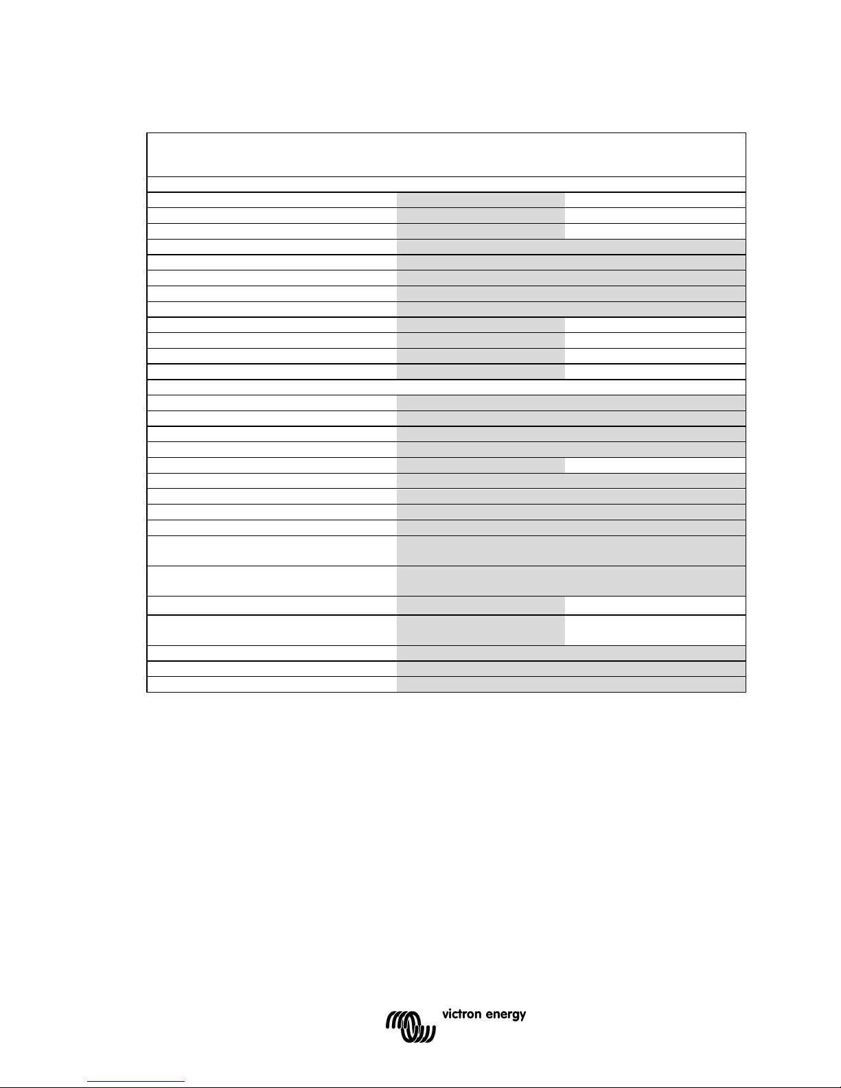
3. Technical data
Phoenix Inverter
12 Volt
24 Volt
48 Volt
12/800
24/800
48/800
12/1200
24/1200
48/1200
INVERTER
Cont. AC power at 25 °C (VA)
(1)
800 1200
Cont. power at 25 °C / 40 °C (W)
700 / 650 1000/ 900
Peak power (W)
1600 2400
Output AC voltage / frequency
120VAC +/- 5% or 230VAC +/- 3% 50Hz or 60Hz +/- 0,1%
Input voltage range (V DC)
9,2 - 17,3 / 18,4 - 34,0 / 36,8 - 68,0
Low battery alarm (V DC)
10,9 / 21,8 / 43,6
Low battery shut down (V DC)
9,2 / 18,4 / 36,8
Low battery restart (V DC)
12,5 / 25 / 50
Max. efficiency (%)
91 / 93 / 94 92 / 94 / 94
Zero-load power 12 / 24 / 48 V (W)
6 / 6 / 6 8 / 9 / 8
Zero-load power in Search Mode (W)
2 2,3
Search Mode shut down / turn on (W)
20 / 30 20 / 30
GENERAL
Protection
(2)
a - e
Remote on-off
Yes
Operating temperature range
-40 to +50°C (fan assisted cooling)
Humidity (non condensing)
max 95%
Internal DC fuse (type: MIDI fuse) (A)
200 / 100 / 60 200 / 150 / 100
ENCLOSURE
Material & Colour Aluminium Blue Ral 5012
Protection category
IP 20
Battery-connection Battery cables of 1.5 meter
Standard AC outlet
230V: IEC-320 (IEC-320 plug included), CEE 7/4 (Schuko)
120V: Nema 5-15R
Other outlets (at request)
BS 1363 (United Kingdom)
AN/NZS 3112 (Australia, New Zealand)
Weight (kg / lbs)
6,5 / 14.3 8,5 / 18.7
Dimensions (hxwxd in mm)
(hxwxd in inches)
108x165x305
4.2x6.4x11.9
108x165x305
4.2x6.4x11.9
STANDARDS
Safety
EN 60335-1
Emission / Immunity
EN55014-1 / EN 55014-2 / EN 61000-6-2 / EN 61000-6-3
1. Non linear load, crest factor 3:1
2. Protection
a. Output short circuit
b. Overload
c. Battery voltage too high
d. Battery voltage too low
e. Temperature too high
 Loading...