

Victron energy Phoenix 12/300, Phoenix 12/500, Phoenix 24/500, Phoenix 24/900 User Manual

USER MANUAL
GEBRUIKSAANWIJZING
Phoenix 12/300
Phoenix 12/500
Phoenix 24/500
Phoenix 24/900


manual 3
SECTIONS page
English 7
Nederlands 37

4 manual
manual 5
USER MANUAL
Phoenix 12/300
Phoenix 12/500
Phoenix 24/500
Phoenix 24/900

6 manual

manual 7
INTRODUCTION
Victron Energy has established an international reputation as a leading
designer and manufacturer of energy systems. Our R&D department is the
driving force behind this reputation. It is continually seeking new ways of
incorporating the latest technology in our products. Each step forward
results in value adding of technical and economical features.
Our proven philosophy has resulted in a full range of state-of-the-art
equipment for the supply of electrical power. All our equipment meets the
most stringent requirements.
Victron Energy energy systems provide you with high quality AC supplies
at places where there are no permanent sources of mains power.
An automatic stand-alone power system can be created with a
configuration comprising a Victron Energy inverter, battery charger, mains
manager (if required) and, last but not least, batteries with sufficient
capacity.
Our equipment is suitable for countless situations in the field, on ships or
other places where a mobile 230 Volt
AC
power supply is indispensable.
Victron Energy has the ideal power source for all kinds of electrical
appliances used for household, technical and industrial purposes, including
instruments susceptible to interference. All of these applications require a
high quality power supply in order to function properly.
Victron Phoenix inverter
This manual contains directions for installing the Phoenix inverter. It
describes the functionality and operation of the Phoenix inverter, including
its protective devices and other technical features.

8 manual
CONTENTS
1. DESCRIPTION ..............................................10
1.1 General .......................................................................10
1.2 Victron Phoenix inverter ..............................................10
2. SAFETY .........................................................12
2.1 Short circuit protection ................................................12
2.2 Short term power / surge power limitation ..................12
2.3 Temperature protection...............................................12
2.4 Low input voltage protection .......................................13
2.4.1 12 Volt
DC
battery 13
2.4.2 24 Volt
DC
battery 13
2.4.3 Alarm indication ‘low batt.’ 13
2.5 High input voltage protection.......................................13
2.5.1 12 Volt
DC
battery 13
2.5.2 24 Volt
DC
battery 13
2.6 Reversed polarity ........................................................13
2.7 Ripple voltage protection.............................................14
3. INSTALLATION AND CONNECTION............15
3.1 Location.......................................................................15
3.2 Installation requirements.............................................15
3.2.1 Installation equipment 15
3.2.2 Battery cables 15
3.3 Connections ................................................................16
3.4 Connecting the battery cables.....................................17
3.5 Connecting the 230 V
ac
cables....................................18
3.6 Remote control connection .........................................19
3.7 Various points of attention ..........................................19
4. OPERATION..................................................20
4.1 LED indications ...........................................................20
4.2 On/off/economy switch................................................20
4.3 Overload indication .....................................................20
4.4 Low battery indication .................................................21
4.5 Temperature indication ...............................................21
4.6 Adjustments ................................................................21
4.6.1 Adjusting output level 21
4.6.2 Unloaded output voltage 21
4.7 Economy mode ...........................................................22
4.8 Maintenance................................................................22

manual 9
5. BATTERY CAPACITY....................................23
6. FAULT TRACING LIST..................................25
6.1 General .......................................................................25
6.2 Trouble shooting .........................................................25
6.3 The ac output voltage is too low..................................27
7. SPECIFICATIONS .........................................28
7.1 Input ............................................................................28
7.2 Output .........................................................................29
7.3 Economy mode ...........................................................30
7.4 General .......................................................................30
7.5 Mechanical..................................................................31
8. DRAWINGS ...................................................32
8.1 Dimensions .................................................................33
8.2 Connection diagram ....................................................34
10 manual
1. DESCRIPTION
1.1 G
ENERAL
All Victron Phoenix inverters are tested to ensure correct functioning
before leaving the factory. They are packed first in shock-absorbing
polystyrene and then in sturdy cardboard boxes for secure transportation.
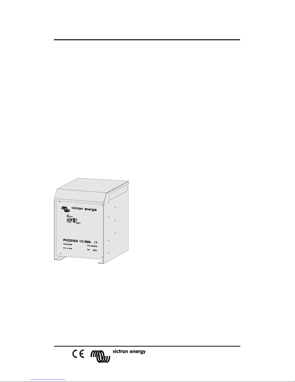
The Victron Phoenix is housed in a robust aluminum cabinet (IP21)
suitable for floor or wall mounting. The AC output terminals, the DC
battery terminals and the terminals for a remote control switch (if used)
can be reached by opening the front of the cabinet with a screwdriver.
1.2 V
ICTRON PHOENIX INVERTER
The coding of the Phoenix inverter model is composed as follows:
For example Phoenix 12/500:
‘12’ = 12 V
DC
= battery voltage
‘500’ = 500 W = continuous electrical
load
The Victron Phoenix inverter is
designed for 12 or 24 V
DC battery
input
voltages and produces a sinusoïdal
output voltage of 230 V
AC
, 50 Hz
(crystal controlled).
Continuous power can be delivered at
all times (see the specifications).
The inverter is developed to serve AC equipment requiring a high quality
energy input. That is, when correct functioning is dependent on true
sinewave supplies such as: computers, satellite communications
equipment, and precision measuring instruments, particularly in mobile
applications.
The Phoenix inverter uses high frequency switching techniques in
combination with a low frequency transformer resulting in a very high
manual 11
efficiency for the user. For power consumption in a no-load
situation, see section 7.1.
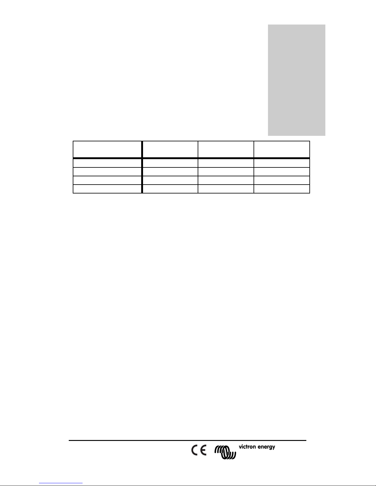
The power supply of the Phoenix inverter is:
continuous
(1)
power
short term
(2)
power
surge power
(3)
Phoenix 12/300 300 W 400 W 1300 W
Phoenix 12/500 500 W 650 W 1350 W
Phoenix 24/500 500 W 750 W 1400 W
Phoenix 24/900 900 W 1000 W 2500 W
1. Continuous power: the continuous power at 40°C ambient temperature.
2. Short term power: the power during 30 minutes at 40°C ambient temperature.
3. Surge power: the power during 3 seconds at 40°C ambient temperature.
Watt =
unit of power
Volt =
unit of voltage
Volt
RMS
=
root mean square
(effective value of
alternating wave)
Hertz =
unit of frequency
 Loading...