

Victron energy 12 120V, 24 120V, Phoenix 12/3000/120V, Phoenix 24/3000/120V User Manual

Manual
EN
Appendix
Phoenix Inverter (with firmware xxxx1xx)
12 | 3000 | 120V
24 | 3000 | 120V


Copyrights 2007 Victron Energy B.V.
All Rights Reserved
This publication or parts thereof may not be reproduced in any form, by any method,
for any purpose.
For conditions of use and permission to use this manual for publication in other than
the English language, contact Victron Energy B.V.
VICTRON ENER GY B.V. MAKES NO WARRANTY, EITHER EXPRESSED O R
IMPLIED, INCLUDING BUT NOT LIMITED TO ANY IMPLIED WARRANTIES OF
MERCHANTABILITY OR FITNESS F OR A PARTI CULAR PURPOSE, REGARDING
THESE VICTRON ENERGY PRODUCTS AND MAKES SUCH VICTRON E NERGY
PRODUCTS AVAILABLE SOLELY ON AN “AS IS” BASIS.
IN NO EVENT SHALL VICTRON EN ER G Y B.V. BE LIABLE TO ANYONE FOR
SPECIAL, COLLATERAL, INCIDENTAL, OR CONSEQUENTIAL DAMAGES IN
CONNECTION WITH OR ARISING OUT OF PURCHASE OR USE OF THESE
VICTRON ENERGY PRODUCTS. THE SOLE AND EXCLUSI VE LIAB ILITY TO
VICTRON ENERGY B.V., REGARDLESS OF THE FORM OF ACTION, SHALL NOT
EXCEED THE PURCHASE PRICE OF THE VICTRON ENERGY PRODUCTS
DESCRIBED HERE IN.
Victron Energy B.V. reserves the right to revise and improve its products as it sees fit.
This publication describes the state of this product at the time of its publication and
may not reflect the product at all times in the future


EN Appendix
1. SAFETY INSTRUCTIONS
In general
Please read the documentation supplied with this product first, so that you are familiar
with the safety signs en directions before using the product.
This product is designed and tested in accordance with international standards. T he
equipment should be used for the designated application only.
WARNING: DANGER OF ELECTRIC AL SHOCK
The product is used in combination with a permanent energy source (battery). Even if
the equipment is switched off, a dangerous electrical voltage can occur at the input
and/or output terminals. Always switch the AC power off and disconnect the battery
before performing maintenance.
The product contains no internal user-serviceable parts. Do not remove the front panel
and do not put the product into operation unless all panels are fitted. All maintenance
should be performed by qualified personnel.
Never use the product at sites where gas or dust explosions could occur. Refer to the
specifications provided by the manufacturer of the battery to ensure that the battery is
suitable for use with this product. The battery manufacturer's safety instructions
should always be observed.
WARNING: do not lift heavy objects unassisted.
Installation
Read the installation instructions before commencing installat i on activities.
This product is a safety class I device (supplied with a ground terminal for safety
purposes). The chassis must be grounded. A grounding point is located on the
outside of the product. If it can be assumed that the grounding protection is damaged,
the product should be taken out of operation and prevented from accidentally being
put into operation again; contact qualified maintenance pers onnel.
Ensure that the connection cables are provided with fuses and circuit breakers. Never
replace a protective device by a component of a different type. Refer to the manual for
the correct part.
Check before switching the device on whether the available voltage source conforms
to the configuration settings of the product as described in the manual.
Ensure that the equipment is used under the correct operating conditions. Never
operate it in a wet or dusty environment.
Ensure that there is always sufficient free space around the product for ventilation,
and that ventilation openings are not blocked.

Install the product in a heatproof environment. Ensure therefore that there are no
chemicals, plastic parts, curtains or other textiles, etc. in the immediate vicinit y of the
equipment.
Transport and storage
On storage or transport of the product, ensure that the battery leads are disconnected.
No liability can be accepted for damage in transit if the equipment is not transported in
its original packaging.
Store the product in a dry environment; the storage temperature should range from
–20°C to 60°C.
Refer to the battery manufacturer's manual for information on trans port, st orage,
charging, recharging and disposal of the battery.

EN Appendix
2. DESCRIPTION
SinusMax - Superior engineering
Developed for professional duty, the Phoenix range of inverters is suitable for the
widest range of applications. The design criteria have been to produce a true sine
wave inverter with optimised efficiency but without compromise i n performance.
Employing hybrid HF technology, the result is a top quality product with compact
dimensions, light in weight and capable of supplying power, problem-free, t o any load.
Extra start-up pow er
A unique feature of the SinusMax technology is very high start-up power.
Conventional high frequency technology does not offer s uch extreme performance.
Phoenix inverters, however, are well suited to power up difficult loads such as
compressors, electric motors and similar appliances.
Virtually unlimited power thanks to parallel and 3-phase operation capability
Up to 6 inverters can operate in parallel to achieve higher power output. Six 24/3000
units, for example, will provide 18kVA output power. Operation in 3-phase
configuration is also possible.
To transfer the load to another AC source: the automatic transfer switch
If an automatic transfer switch is required, we recommend to using the MultiPlus or
Quattro instead. The switch is included in these products and the charger functi on of
the MultiPlus/Quattro can be disabled. Computers and other elect ronic equi pm ent will
continue to operate without disruption because the MultiPlus/Quattro features a very
short switchover time (less than 20 milliseconds).
Programmable relay
The Phoenix Inverter is equipped with a programmable relay, which by default is set
as an alarm relay. The relay can be programmed for all kinds of other applications
however, for example as a starter relay for a generating set.
Programmable with DIP switches, VE.Net panel or personal computer
The Phoenix Inverter is supplied ready for use. Three features are available for
changing certain settings if desired:
─ The most important settings (including parallel operation of up to three devices
and 3-phase operation) can be changed in a very simple manner, using DIP
switches.
─ All settings, with exception of the programmable relay, can be changed with a
VE.Net panel.
─ All settings can be changed with a PC and free of charge software,
downloadable from our website www.victronenergy.com
3. OPERATION
3.1 On/Off Switch
When switched to "on", the product is fully functional. The inverter will come into
operation and the LED "inverter on" will light up.
3.2 Remote control
Remote control is possible with a simple on/off switch or with a Phoenix Inverter
Control panel.
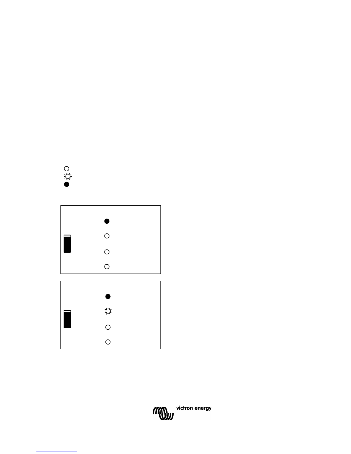
3.3 LED Indications
LED off
LED flashes
LED illuminated
Inverter
Inverter
The inverter is on and supplies
power to the load.
on
inverter on
Overload
low battery
off
Temperature
Inverter
The nominal output of the inverter is
exceeded. The “overload” LED
flashes.
on
inverter on
Overload
low battery
off
Temperature
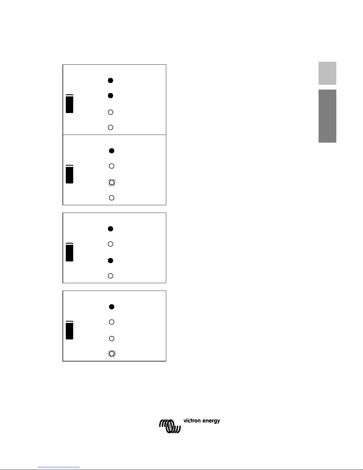
EN Appendix
Inverter
The inverter is switched off due to
overload or short circuit.
on
inverter on
Overload
low battery
off
Temperature
Inverter
The battery is almost fully
exhausted.
on
inverter on
Overload
low battery
off
Temperature
Inverter
The inverter has switched off due to
low battery voltage.
on
inverter on
Overload
low battery
off
temperature
Inverter
The internal temperature is reaching
a critical level.
on
inverter on
overload
low battery
off
temperature
 Loading...