

Victron energy Phoenix Inverter Smart 24/1600, Phoenix Inverter Smart 48/2000, Phoenix Inverter Smart 48/1600, Phoenix Inverter Smart 12/1600, Phoenix Inverter Smart 24/2000 Series Manual
...
Manual
Handleiding
l
Anleitung
Manual
Användarhandbok
Phoenix Inverter Smart
EN
NL
Manue
FR
DE
ES
SE
Appendix
12 | 1600 230V 12 | 2000 230V
24 | 1600 230V 24 | 2000 230V
48 | 1600 230V 48 | 2000 230V


1. SAFETY INSTRUCTIONS
General
Please familiarize yourself with the safety features and instructions by first reading the
documentation supplied with this product before using the equipment. This product has
been designed and tested in accordance with international standards. The equipment
must be used exclusively for the purpose for which it was designed.
WARNING: ELECTRIC SHOCK HAZARD.
The product is used in combination with a permanent energy source (battery). Even if the
equipment is switched off, a dangerous electrical voltage can occur at the input and/or
output terminals. Always disconnect the battery before performing maintenance.
The product has no internal user-serviceable components. Do not remove the front plate
or operate the product if any panels have been removed. All servicing must be
undertaken by qualified personnel.
Never use the product where there is a risk of gas or dust explosions. Consult the battery
manufacturer's information to ascertain that the product is intended for use in conjunction
with the battery. Always comply with the battery manufacturer's safety instructions.
WARNING: Do not lift heavy loads without assistance.
Installation
Read the installation instructions in the installation manual before installing the
equipment.
This is a Safety Class I product (supplied with a protective grounding terminal). The chassis
must be grounded. A grounding point is located on the outside of the product. Whenever it is
likely that the grounding protection has been damaged, the product must be turned off and
secured against unintended operation; please contact qualified service staff.
Ensure that the DC and AC input cables are fused and fitted with circuit breakers. There is no
internal fuse inside this product. Never replace a safety component with a different type.
Consult the manual to determine the correct component.
During installation ensure that the remote connector with wire bridge is removed (or swtich off
the remote on/off switch if installed) to be sure that the inverter cannot be switched on
unexpectedly.
Before applying power, ensure that the available power source matches the configuration
settings of the product as described in the manual.
Ensure that the equipment is used under the correct ambient conditions. Never operate the
product in a wet or dusty environment. Ensure there is adequate free space for ventilation
around the product and check that the ventilation vents are not blocked.
Ensure that the required system voltage does not exceed the product's capacity.
EN NL FR DE ES SE Appendix
1

Transport and Storage
Ensure that the mains power and battery leads have been disconnected before storing or
transporting the product.
No liability can be accepted for any transport damage if the equipment is shipped in nonoriginal packaging.
Store the product in a dry environment; the storage temperature must be between -20°C and
60°C.
Consult the battery manufacturer's manual in respect of transport, storage, charging,
recharging and disposal of the battery.
2

2. DESCRIPTION
2.1 General
Bluetooth built-in: fully configurable with a tablet or smartphone
• Low battery voltage alarm trip and reset levels
• Low battery voltage cut-off and restart levels
• Dynamic cut-off: load dependent cut-off level
• Output voltage: 210 - 245V
• Frequency: 50 Hz or 60 Hz
• ECO mode on/off and ECO mode sense level
• Alarm relay
Monitoring:
• In- and output voltage, % load and alarms
VE.Direct communication port
The VE.Direct port can be connected to a computer (VE.Direct to USB interface cable
needed) to configure and monitor the same parameters.
Proven reliability
The full bridge plus toroidal transformer topology has proven its reliability over many
years.
The inverters are short circuit proof and protected against overheating, whether due to
overload or high ambient temperature.
High start-up power
Needed to start loads such as power converters for LED lamps, halogen lamps or electric
tools.
ECO mode
When in ECO mode, the inverter will switch to standby when the load decreases below a
preset value (min load turn on level: 10VA; and min load turn off level: 0VA). Once in standby
the inverter will switch on for a short period (adjustable, default: every 3 seconds). If the load
exceeds a preset level, the inverter will remain on.
Remote on/off
A remote on/off switch can be connected to a two pole connector, between battery plus and
the left hand contact of the two pole connector or between battery minus and the right hand
contact of the two pole connector
LED diagnosis
See section 3.3
To transfer the load to another AC source: the automatic transfer switch
For our low power inverters we recommend our Filax Automatic Transfer Switch. The Filax
features a very short switchover time (less than 20 milliseconds) so that computers and other
electronic equipment will continue to operate without disruption. Alternatively use a MultiPlus
with built-in transfer switch.
EN NL FR DE ES SE Appendix
3
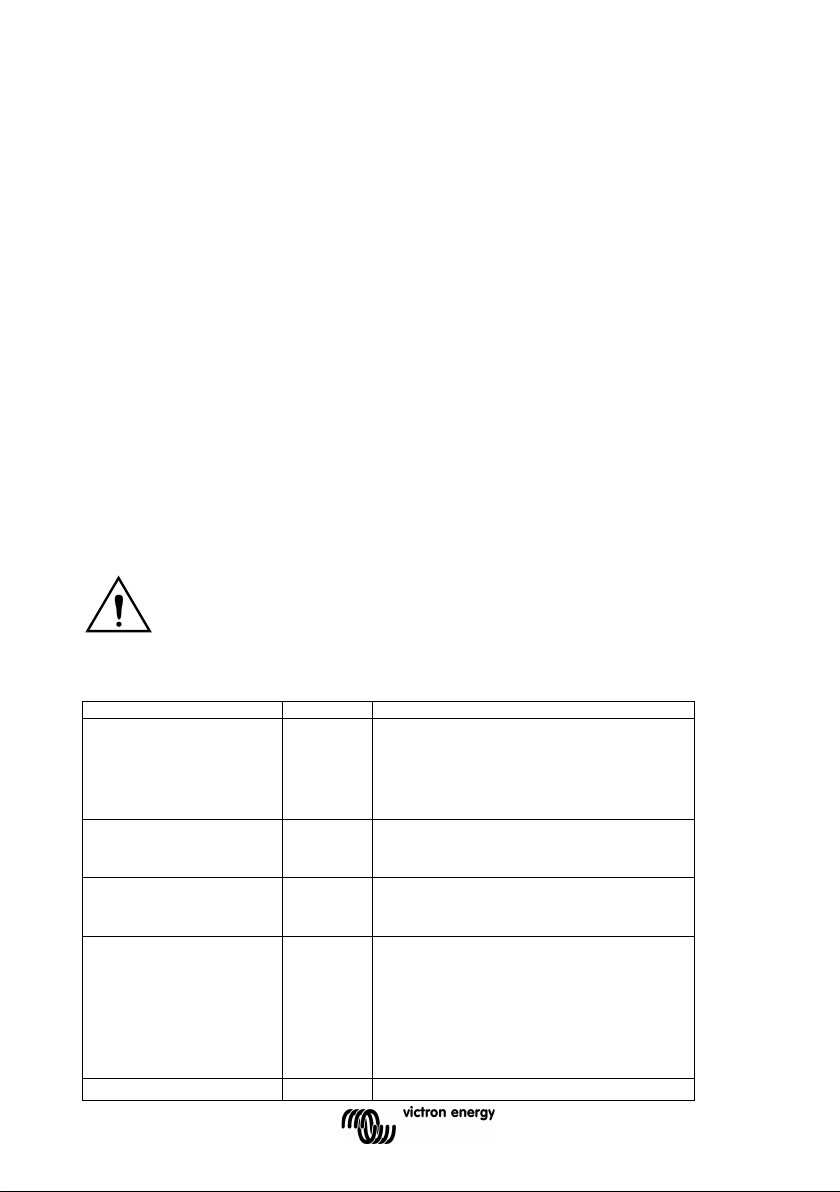
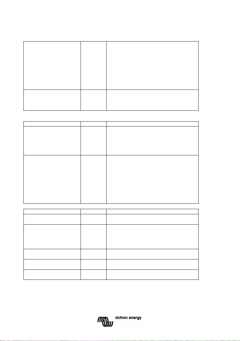
For safety purposes, this product can be turned off completely (i.e. the inverter
switched on accidently via Bluetooth by an unexpected other user.
Green LED
Status
Trouble shooting
●●●●●●●●
Inverter on
Red LED Off
reason
●●------ Slow
ECO mode
If the inverter keeps switching on and off while there is a
ECO mode settings. (minimum ECO mode setting: 15W)
●-●-----
Off and waiting
Inverter did shut down because of a protection. The
reason.
-------- Off
Inverter off
Red LED Off
the inverter by switching it Off, and then back On.
●-●-●-●- Fast
Off and
Red LED Blinking (-●-●-●-●)
3. OPERATION
3.1 On/Off Switch
When switched to "on" with the push button, the product is fully functional. The inverter will
come into operation and the LED "inverter" will light up. By pushing the push button
subsequently, within a short period of time, the inverter toggles between “on”, “ECO” and “off”.
Apart from the pushbutton; the inverter can also be switched on (normal or ECO) and off with
Bluetooth on a mobile device running iOS or Android and the Victron Connect app. However
when switched off via Bluetooth or the push button; the unit cannot be switched on and off
again via the wired VE.Direct port.
3.2 Remote control
Remote control is possible with a simple on/off switch or with a Phoenix Inverter Control
panel. A switch for remote control (on/off) can be connected to a two pole connector. The
switch can also be connected between battery plus and the left hand contact of the two pole
connector (marked “H”; see appendix A) or between battery minus and the right hand contact
of the two pole connector (marked “L”; see appendix A).
3.3 LED definitions
cannot be switched on via the push button or Bluetooth) by removing the remote
connector and its default installed wire bridge (or swtich off the remote on/off
switch if installed). The user can then be certain that the inverter cannot be
Solid on
single pulse
double pulse
4
Fast
status OK
Red LED On or blinking:
The Inverter is still on, but will shut down when the
condition gets worse. See red LED table for warning
load connected, the load may be too small compared to the
actual ECO mode settings. Increase the load or change
inverter will restart automatically as soon as all alarm
conditions are cleared. See red LED state for the shutdown
Check Remote on/off connector.
Check DC cable connections and fuses.
Check operational mode by pushing push button one time.
Red LED On or blinking
The inverter did shut down because of a protection. It will
no longer automatically restart. The red LED indicates the
reason for shutdown. Remove the cause and then restart
blink
frirmware
failed
Firmware update in progress or firmware update failed.
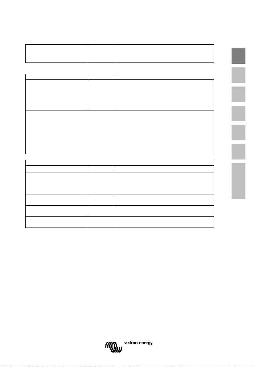
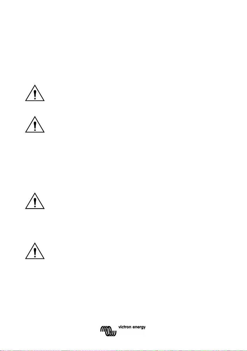
Yellow LED
Status
Trouble shooting
●●●●●●●●
ECO mode
Red LED Off
reason
-------- Off
ECO mode off
Red LED Off
the inverter by switching it Off, and then back On.
Red LED
Definition
Trouble shooting
●●●●●●●● Solid on
Overload
Reduce load
●●●●---- Slow
Low batt.
Recharge or replace battery
manual and automatic restart behavior.
●-●-●-●-
blink
High batt.
●-●-----
pulse
High temp.
●---●--- Fast
single pulse
High DC ripple
Solid on
blink
Fast
Double
3.4 Protections and automatic restarts
Overload
Some loads like motors or pumps draw large inrush currents in a start-up situation. In such
circumstances, it is possible that the start-up current exceeds the over current trip level of the
inverter. In this case the output voltage will quickly decrease to limit the output current of the
inverter. If the over current trip level is continuously exceeded, the inverter will shut down: wait
30 seconds and then restart.
After three restarts followed by another overload within 30 seconds of restarting, the inverter
will shutdown and remain off. The LEDs will signal shutdown due to overload. To restart the
inverter, switch it Off, then On.
Low battery voltage (adjustable)
The inverter will shut down when the DC input voltage drops below the low battery shutdown
level. After a minimum delay of 30 seconds, the inverter will restart if the voltages rise above
the low battery restart level.
update in
progress or
When failed; retry firmware update.
status OK
Red LED On or blinking:
The Inverter is still on, but will shut down when the
condition gets worse. See red LED table for warning
Check operational mode by pushing push button one time.
Check Remote on/off connector.
Check DC cable connections and fuses.
Red LED On or blinking
The inverter did shut down because of a protection. It will
no longer automatically restart. The red LED indicates the
reason for shutdown. Remove the cause and then restart
Check DC cable connections
Check cable cross section as it may be insufficient.
See section 4.2 Protections and automatic restarts for
Reduce DC input voltage, check for faulty charger
Reduce load and/or move inverter to better ventilated area
Check DC cable connections and cable cross section.
EN NL FR DE ES SE Appendix
5

After three restarts followed by a low battery shutdown within 30 seconds of restarting, the
inverter will shutdown and stop retrying. The LEDs will signal low battery shutdown. To restart
the inverter, switch it Off, and then On, or recharge the battery: as soon as the battery has
risen and then stays above the Charge detect level for 30 seconds, it will switch on.
See the Technical Data table for default low battery shutdown and restart levels. They can be
changed with the VictronConnect App.
High battery voltage
Reduce DC input voltage and/or check for a faulty battery- or solar-charger in the system.
After shutting down due to a high battery voltage, the inverter will first wait 30 seconds and
then retry operation as soon as the battery voltage has dropped to acceptable level. The
inverter will not stay off after multiple retries.
High temperature
A high ambient temperature or enduring high load may result in shut down to over
temperature. The inverter will restart after 30 seconds. The inverter will not stay off after
multiple retries. Reduce load and/or move inverter to better ventilated area.
High DC ripple
High DC ripple is usually caused by loose DC cable connections and/or too thin DC wiring.
After the inverter has switched off due to high DC ripple voltage, it waits 30 seconds and then
restarts.
After three restarts followed by a shutdown due to high DC ripple within 30 seconds of
restarting, the inverter will shutdown and stops retrying. To restart the inverter, switch it Off
and then On.
Continuous high DC ripple reduces the inverter life expectancy.
6
Excessively high ambient temperature will result in the following:
Never mount the appliance directly above the batteries.
For safety purposes, this product should be installed in a heat-resistant
immediate vicinity.
cannot be switched on unexpectedly.
4. INSTALLATION
This product should be installed by a qualified electrician.
During installation ensure that the remote connector with wire bridge is removed
(or swtich off the remote on/off switch if installed) to be sure that the inverter
4.1 Location
The product must be installed in a dry and well-ventilated area, as close as possible to
the batteries. There should be a clear space of at least 10cm around the appliance for
cooling.
Reduced service life.
Reduced charging current.
Reduced peak capacity, or shutdown of the inverter.
The product is suitable for wall mounting. For mounting see appendix A.
The appliance can be mounted horizontally as well as vertically; vertical mounting is
preferable. The vertical position offers optimum cooling.
EN NL FR DE ES SE Appendix
The interior of the product must remain accessible after installation.
Try and keep the distance between the product and the battery to a minimum in order to
minimize cable voltage losses.
environment if it is used with equipment where a substantial amount of
power is to be converted. You should prevent the presence of e.g.
chemicals, synthetic components, curtains or other textiles, etc., in the
7
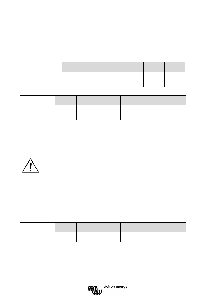
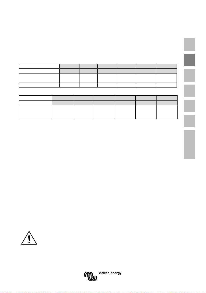
12/1600
24/1600
48/1600
12/2000
24/2000
48/2000
Recommended
cross section (mm2)
length up to 6 m
50
25
25
70
35
25
12/1600
24/1600
48/1600
12/2000
24/2000
48/2000
Recommended
(Ah)
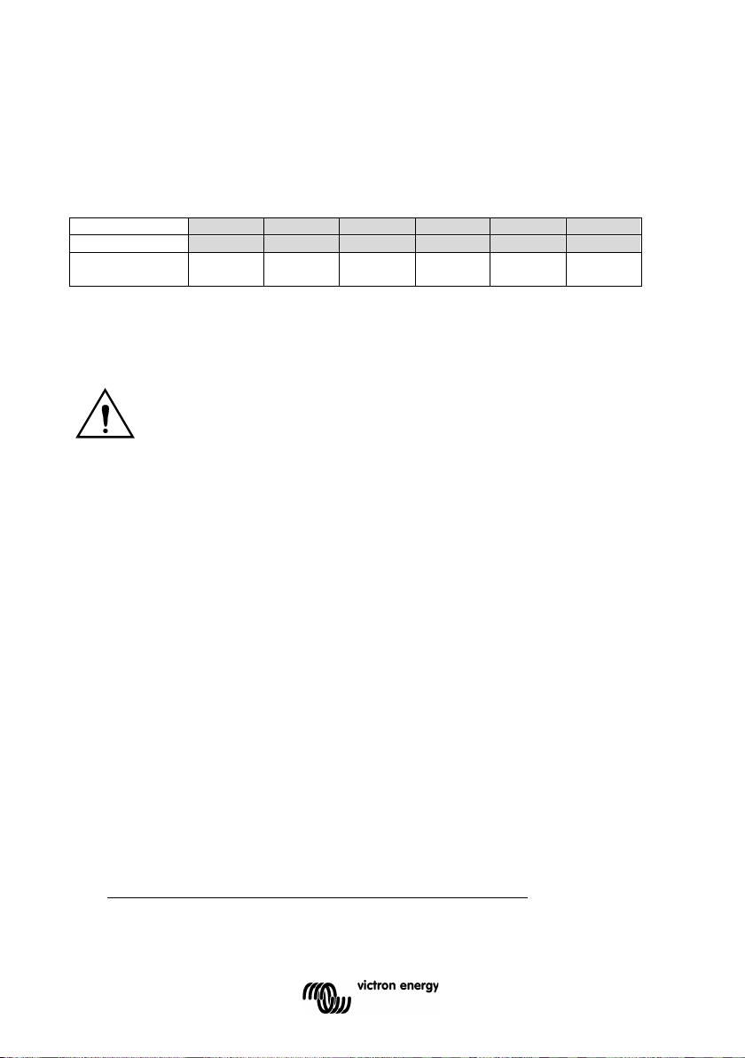
12/1600
24/1600
48/1600
12/2000
24/2000
48/2000
Recommended
DC fuse
4.2 Connection of Battery cables
In order to fully utilize the full capacity of the product, batteries with sufficient capacity and
battery cables with sufficient cross section should be used. See table.
battery capacity
Remark: Internal resistance is the important factor when working with low capacity batteries.
Please consult your supplier or the relevant sections of our book “electricity on board”,
downloadable from our website.
Procedure
Proceed as follows to connect the battery cables:
Connect the battery cables: the + (red) and the - (black), to the battery see appendix A.
Reverse polarity connection (+ to – and – to +) will cause damage to the product.
Secure the nuts tightly in order to reduce the contact resistance as much as possible.
300 - 800 150 - 400 75 - 200 350 - 1000 200 - 500 100 - 250
Use an insulated box spanner in order to avoid shorting the battery.
Avoid shorting the battery cables.
4.3 DC safety fuse
There is no safety fuse inside the inverter; this should be installed externally. The
recommended safety fuses can be found in the table below
250A 125A 60A 300A 150A 80A
8
This is a Safety Class I product (supplied with a protective grounding
vehicle) or the ground plate or hull (of a boat).
4.4 Connection of the AC cabling
terminal).
The neutral wire of the AC output of this inverter is connected to the
chassis (see appendix B).
This is to ensure proper functioning of a GFCI (or RCCB) to be installed in the
AC output of the Inverter.
The chassis of the product must be connected to ground, to the frame (of a
Procedure
The terminal points are indicated clearly. From left to right: “L” (phase), “N” (neutral) and
“PE” (earth).
4.5 Optional Connections
A number of optional connections are possible:
4.5.1 Remote on/off switch & remote Control panel
The product can be remotely controlled in three ways.
- With a smart phone (iOS or Android) and the Victron Connect app.
- With an external switch (connected to the two pole remote connector). Operates only
if the switch on the Inverter is set to “on”.
- With a Phoenix Inverter Control VE.Direct panel (connected to the two pole remote
connector; see appendix A). Operates only if the switch on the inverter is set to “on”.
4.5.2. Programmable relay
The inverters are equipped with a multi-functional relay that by default is programmed in the
normal operation mode. (VictronConnect software needed to change relay functionality). The
different relay modes can be summerized as follows:
- Normal operation (“inverter” in VictronConnect app) – default
Relay closed during normal operation, and open when the inverter has switched off itself
in alarm, has been switched off by a user and also open (of course) when there is no
power available on the terminals, ie. battery disconnected. In ECO mode, the relay will
be closed both when searching for a load and when fully on, ie. load detected.
Use this option when you want the relay to signal that there is power available on the
output of the inverter.
- Warnings and alarms (“alarm” in VictronConnect app)
Similar to above, but then the relay will also open when there is a warning. For example
because the battery voltage dropped to the cut-off value, or when loaded to the point
where it will almost shut down due to overload. In ECO mode, the relay will be closed
both when searching (no load) and when fully on (load detected), except when there is a
warning.
Use this option when you want the relay to signal that it is time to do something (charge
the battery, reduce the load, and-so-forth), in order to prevent a power outage.
- Low battery (“Low battery” in VictronConnect app)
EN NL FR DE ES SE Appendix
9

Relay on during normal operation. The relay will switch off once there is a low battery
warning. It will remain off in case the inverter shuts down due to low voltage, and will
only switch back on again once the inverter is operational and the battery voltage is
above the pre-alarm reset level. Use this option for load shedding, or to automatically
start a generator. Note that this can only be considered a poor-mans generator
start/stop. For more and better options, see here.
- External fan (“fan” in VictronConnect app)
Relay is off, unless the fan inside the inverter is running. Use this option to switch an
external fan, for situations when the inverter is in a small enclosed space.
- Disabled relay (“off” in VictronConnect app)
This option sets the relay in the OPEN position. Use this option if you do not plan to use
the relay function.
10
Settings may only be changed by a qualified engineer.
Batteries should be placed in a dry and well-ventilated area during charging.
5. CONFIGURATION
Carefully read the instructions before changes are made.
5.1 Standard settings: ready for use
On delivery, the Phoenix inverter is set to standard factory values. In general, these
settings are suitable for stand-alone operation.
Standard factory settings
Inverter frequency 50 Hz
Inverter voltage 230 VAC
Search mode off
Programmable relay alarm function
Dynamic cut-off off
5.2 Explanation of settings
Inverter frequency
Output frequency
Adjustability: 50Hz; 60Hz
Inverter voltage
Adjustability: 210 – 245V
ECO Mode
If ECO mode is ‘on’, the power consumption in no-load operation is decreased by approx.
80…90%. In this mode the Phoenix Inverter Smart, when operating in inverter mode, is
switched off in case of no load or very low load, and switches on every two and a half seconds
for a short period (adjustable). If the output current exceeds a set level, the inverter will
continue to operate. If not, the inverter will shut down again.
The ECO Mode can be set with the push button on the front of the inverter.
The ECO Mode “shut down” and “remain on” load levels can be set with Victron Connect .
The factory settings are:
Shut down: 50 Watt (linear load).
Turn on: 100 Watt (linear load).
Programmable relay
By default, the programmable relay is set as an alarm relay, i.e. the relay will de-energise in
the event of an alarm or a pre-alarm (inverter almost too hot, ripple on the input almost too
high, battery voltage almost too low).
EN NL FR DE ES SE Appendix
11

Dynamic Cut-off
Use VictronConnect to enable and configure Dynamic Cut-off (see
https://www.victronenergy.com/live/ve.direct:phoenix-inverters-dynamic-cutoff for details).
Do not use Dynamic Cut-off in an installation that also has other loads connected to the same
battery: the battery voltage will drop because of the extra load, but the Dynamic Cut-off
algorithm in the Inverter is not aware of that load: hence the Inverter will shut down too early
with an under voltage alarm.
5.3 Configuration by computer
All settings can be changed by means of a smartphone, tablet or computer
For changing settings with a smartphone or tablet, the following is required:
- VictronConnect software: can be downloaded free of charge at www.victronenergy.com.
For changing settings with the computer, the following is required:
- VictronConnect software: can be downloaded free of charge at www.victronenergy.com.
- A VE.Direct to USB interface.
6. MAINTENANCE
The Phoenix Inverter Smart does not require specific maintenance. It will suffice to check all
connections once a year. Avoid moisture and oil/soot/vapours, and keep the device clean.
12
12 Volt
48 Volt
12/1600
48/1600
12/2000
48/2000
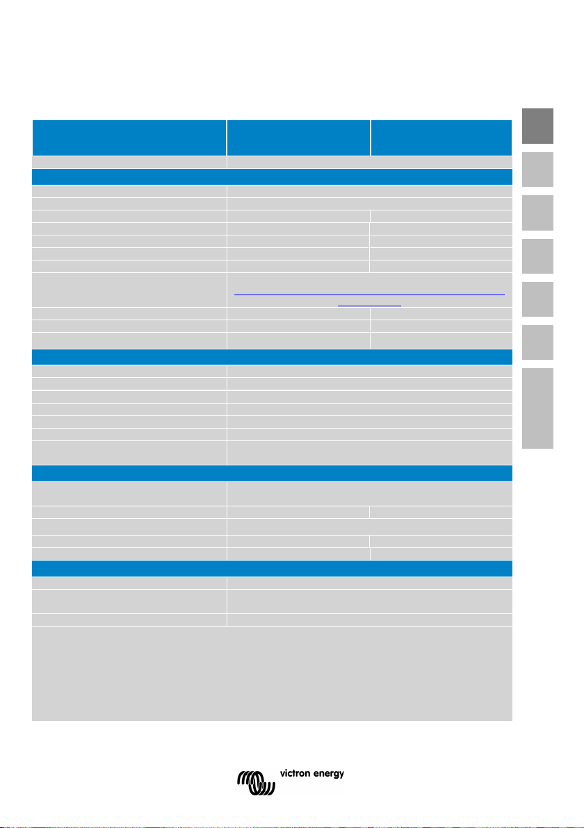
Parallel and 3-phase operation
No
Input voltage range (1)
9,3 – 17V 18,6 – 34V 37,2 – 68V
Output
Output voltage: 230VAC ±2% 50 Hz or 60Hz ± 0,1% (1)
Cont. output power at 25ºC (2)
1600VA
2000VA
Cont. output power at 25ºC
1300W
1600W
Cont. output power at 40ºC
1200W
1450W
Cont. output power at 65ºC
800W
1000W
Peak power
3000VA
4000VA
Dynamic cut-off, see
dynamic-cutoff
Max. efficiency 12/ 24 /48 V
92/94/94 %
92/94/94 %
Zero load power 12 / 24 / 48 V
8/9/11 W
8/9/11 W
Zero load power in ECO mode
Programmable relay (2)
Yes
Stop & start power ECO-mode
adjustable
Protection (3)
a - g
Bluetooth wireless communication
For remote monitoring and system integration
VE.Direct communication port
For remote monitoring and system integration
Remote on-off
Yes
Operating temperature range: -40 to +65ºC (fan assisted cooling)
Humidity (non-condensing): max 95%
Material & Colour: stainless steel (blue RAL 5012; and black RAL
9017) Protection category: IP 21
Battery-connection
M8 bolts
2+2 M8 bolts
Weight
12kg
13kg
Dimensions (hxwhd)
485 x 219 x 125mm
485 x 219 x 125mm
Safety
EN 60335-1
EN 55014-1 / EN 55014-2/ IEC 61000-6-1
IEC 61000-6-2 / IEC 61000-6-3
Automotive Directive
ECE R10-5
1) Non-linear load, crest factor 3:1
7. Technical data
Phoenix Inverter Smart
Dynamic (load dependent) DC low s hut down
(fully configurable)
Common Characteristics
Common Characteristics
24 Volt
24/1600
24/2000
INVERTER
https://www.victronenergy.com/live/ve.direct:phoenix-inverters-
0,6/1,3/2,1 W 0,6/1,3/2,1 W
GENERAL
ENCLOSURE
EN NL FR DE ES SE Appendix
230 V AC-connection Screw terminals
STANDARDS
Emission Immunity
2) Programmable relay that can a.o. be set for general
alarm, DC under voltage or genset start/stop function.
AC rating: 230 V / 3 A
DC rating: 3 A up to 30 VDC, 0.2A up to 70 VDC
3) Protection key:
a) output short circuit
b) overload
c) battery voltage too high
d) battery voltage too low
e) temperature too high
f) 230 V AC on inverter output
g) input voltage ripple too high
13

1) Can be adjusted to 60Hz and to 240V
2) Protection
a. Output short circuit
b. Overload
c. Battery voltage too high
d. Battery voltage too low
e. Temperature too high
f. 230VAC on inverter output
g. Input voltage ripple too high
3) Non linear load, crest factor 3:1
4) Programmable relay which can be set for general alarm, DC undervoltage or genset start signal function
14

1. VEILIGHEIDSINSTRUCTIES
Algemeen
Gelieve op de hoogte te zijn van deze veiligheidskenmerken en instructies door eerst de
meegeleverde documentatie bij dit product goed te lezen voordat u de apparatuur in
gebruik gaat nemen. Dit product is ontworpen en getest in overeenstemming met
internationale normen. De apparatuur mag uitsluitend worden gebruikt voor het doel
waarvoor deze is ontworpen.
WAARSCHUWING: GEVAAR VOOR ELEKTRISCHE SCHOKKEN.
Het product wordt in combinatie met een permanente energiebron (batterij) gebruikt.
Ingangs- en / of uitgangsklemmen kunnen nog steeds gevaarlijk onder stroom staan,
zelfs als de apparatuur is uitgeschakeld. Altijd de AC-voeding en de accu uitschakelen
alvorens onderhouds- of reparatiewerkzaamheden aan de batterij uit te voeren.
Het product is niet uitgerust met interne onderdelen die door de gebruiker kunnen worden
onderhouden. De voorplaat niet verwijderen en bedien het product niet als er panelen zijn
verwijderd. Alle onderhoudswerkzaamheden moeten door gekwalificeerd personeel
worden uitgevoerd.
Het product nooit gebruiken op plaatsen waar gas- of stofexplosies kunnen optreden.
Raadpleeg de informatie van de batterijfabrikant om te controleren of het product is
bestemd voor gebruik in combinatie met de accu. Altijd de veiligheidsinstructie van de
batterijfabrikant opvolgen.
WAARSCHUWING: Geen zware lasten zonder hulp optillen.
Installatie
Lees de installatie-instructies in de installatiehandleiding alvorens u de apparatuur gaat installeren.
Dit is een product van Veiligheidsklasse I (geleverd met een beschermende aardingsterminal). Het
chassis moet worden geaard. Een aardingspunt bevindt zich aan de buitenzijde van het product.
Wanneer het waarschijnlijk is dat de aardbeveiliging is beschadigd, moet het product worden
uitgeschakeld en beveiligd tegen onbedoeld gebruik; gelieve contact op te nemen met
gekwalificeerd onderhoudspersoneel.
Zorg ervoor dat de DC- en AC-ingangskabels zijn beveiligd en voorzien zijn van
stroomonderbrekers. Dit product is niet uitgerust met een interne zekering. Vervang nooit een
veiligheidscomponent door een ander type. Raadpleeg de handleiding om het correcte onderdeel
te bepalen.
Tijdens de installatie moet u controleren of de externe connector met draadbrug is verwijderd (of
schakel de externe aan / uit-schakelaar uit indien geïnstalleerd) teneinde er zeker van te zijn dat de
omvormer niet onverwacht kan worden ingeschakeld.
Zorg ervoor dat de apparatuur wordt gebruikt onder de juiste omgevingsomstandigheden. Het
product nooit bedienen in een natte of stoffige omgeving. U moet ervoor zorgen dat er
voldoende vrije ruimte voor ventilatie rondom het product aanwezig is en controleren of de
ventilatieopeningen niet zijn geblokkeerd.
EN NL FR DE ES SE Appendix
1

Zorg ervoor dat de vereiste systeemspanning de capaciteit van het product niet overschrijdt.
Transport en Opslag
Zorg ervoor dat de netspanning en batterijkabels zijn losgekoppeld voordat u het product gaat
opslaan of vervoeren.
Er wordt geen aansprakelijkheid worden aanvaard voor transportschade als de apparatuur
wordt verscheept in een niet-originele verpakking.
Het product opslaan in een droge omgeving; en de opslagtemperatuur moet tussen -20°C en
60°C zijn.
Raadpleeg de handleiding van de batterijfabrikant voor transport, opslag, laden, opnieuw
laden en verwijderen van de batterij.
2

2. BESCHRIJVING
2.1 Algemeen
Geïntegreerde Bluetooth: volledig configureerbaar met een tablet of smartphone
• Lage batterijspanning alarmuitschakeling en resetniveaus
• Lage batterijspanning-uitschakeling en herstartniveaus
• Dynamische cut-off: belastingafhankelijk cut-off-niveau
• Uitgangsspanning: 210 - 245V
• Frequentie: 50 Hz of 60 Hz
• ECO modus aan/uit en ECO modus gevoelsniveau
• Alarmrelais
Bewaking
• In- en uitgangsspanning,% belasting en alarmen
VE.Direct communicatiepoort
De VE.Direct poort kan op een computer worden verbonden (VE.Direct naar USB
interfacekabel nodig) teneinde dezelfde parameters te configureren en te bewaken.
Bewezen betrouwbaarheid
De volledige bridge plus toroïdale transformatortopologie heeft zijn betrouwbaarheid
gedurende vele jaren bewezen.
De omvormers zijn kortsluitvast en beschermd tegen oververhitting, hetzij door
overbelasting of hoge omgevingstemperatuur.
Hoog startvermogen
Nodig om belastingen te starten, zoals stroomomzetters voor LED-lampen,
halogeenlampen of elektrische gereedschappen.
ECO-modus
In de ECO-modus schakelt de omvormer naar stand-by wanneer de belasting daalt tot onder
een vooraf ingestelde waarde (min. ladingniveau inschakelen: 10VA; en min. ladingniveau
uitschakelen: 0VA). Eenmaal in stand-by schakelt de omvormer voor een korte periode in
(instelbaar, standaard: elke 3,0 seconden). Indien de belasting een vooraf ingesteld niveau
overschrijdt, blijft de omvormer ingeschakeld
EN NL FR DE ES SE Appendix
.
Afstandsbediening aan/uit
Een aan/uit-schakelaar voor afstandsbediening of relaiscontact kan verbonden worden met
een 2-polige connector.
Als alternatief kan de H-terminal (links) van de 2-polige connector geschakeld worden aan
batterij-plus, of de L-terminal (rechts) van de 2-polige connector kan geschakeld worden aan
battery-minus (of het chassis van een voertuig bijvoorbeeld
LED diagnose
Zie paragraaf 3.3
Raadpleeg de handleiding voor een beschrijving.
3

Om de belasting over te dragen naar een andere AC-bron: de schakelaar voor
automatische overdracht
Voor onze low-power omvormers raden we onze Filax Automatic Transfer Switch aan. De
Filax heeft een zeer korte omschakelingstijd (minder dan 20 milliseconden), zodat computers
en andere elektronische apparatuur zonder onderbreking kunnen blijven werken. Gebruik als
alternatief een MultiPlus met ingebouwde schakelaar voor overdracht.
4
3. BEDIENING
Vanwege veiligheidsredenen kan dit product volledig worden uitgeschakeld (dat
gebruiker.
Groen LED
Status
Probleemoplossing
●●●●●●●● Brandt
Omvormer
Rode LED Uitgeschakeld
tabel voor waarschuwingsreden
●●------
ECO-modus
Wanneer de omvormer blijft in- en uitschakelen terwijl er
ECO-modus. (minimum ECO-modusinstelling: 15W)
●-●-----
Uitgeschakeld
Omvormer is uitgeschakeld vanwege een beveiliging. De
reden van de uitschakeling.
3.1 Aan-/Uitschakelaar
Wanneer geschakeld op "on" met de drukknop,is het product volledig functioneel. De
omvormer zal gaan functioneren en de LED "omvormer" zal gaan branden. Door
vervolgens op de drukknop te drukken, binnen een korte tijdsperiode, zal de omvormer
schakelen tussen “on”, “ECO” en “off”
Buiten de drukknop om; de omvormer kan tevens worden in- en uitgeschakeld (normaal
of ECO) met Bluetooth op een mobiel apparaat met iOS of Android en de Victron
Connect-app. Echter wanneer uitgeschakeld via Bluetooth of de drukknop; het apparaat
kan niet opnieuw worden in- en uitgeschakeld via de bedrade VE.Direct-poort.
3.2 Afstandsbediening
Afstandsbediening is mogelijk met een simpele aan-/uitschakelaar of met een Phoenix
Omvormer bedieningspaneel. Een schakelaar voor afstandsbediening (aan/uit) kan
worden aangesloten op een tweepolige connector (gemarkeerd met "H"; zie bijlage A).
De schakelaar kan worden aangesloten tussen batterij plus en het linkercontact van de
tweepolige connector of tussen batterij minus en het rechtercontact van de tweepolige
connector (gemarkeerd met "L", zie bijlage A).
EN NL FR DE ES SE Appendix
wil zeggen, de omvormer kan niet worden ingeschakeld via de drukknop of
Bluetooth) door de externe connector te verwijderen en de standaard
geïnstalleerde draadbrug (of schakel de externe aan / uit-schakelaar uit indien
geïnstalleerd). De gebruiker kan er dan zeker van zijn dat de omvormer niet per
ongeluk via Bluetooth kan worden ingeschakeld door een onverwachte andere
3.3 LED definities
stabiel
ingeschakeld
Langzame enkele puls
Snelle
dubbele puls
en wachten
Status INGESCHAKELD
Rode LED INGESCHAKELD of knippert:
De omvormer is nog steeds ingeschakeld, maar wordt
uitgeschakeld als de toestand verslechtert. Zie rode LED-
een belasting is aangesloten, kan de belasting te klein zijn
in vergelijking met de werkelijke ECO-modusinstellingen.
Verhoog de belasting of verander de instellingen van de
omvormer start automatisch opnieuw zodra alle
alarmcondities zijn gewist. Zie rode LED-status voor de
5
--------
omvormer
Rode LED Uitgeschakeld
deze uit en weer in te schakelen.
●-●-●-●- Snel
Uitschakelen
mislukt
Firmware update wordt uitgevoerd firmware update mislukt.
Gele LED
Status
Probleemoplossing
●●●●●●●● Blijft
ECO-modus
Rode LED Uitgeschakeld
tabel voor waarschuwingsreden
--------
ECO-modus
Rode LED Uitgeschakeld
deze uit en weer in te schakelen.
Rode LED
Definitie
Probleemoplossing
●●●●●●●●
branden
Overbelasting
●●●●----
Batterij bijna
Laad de batterij op of vervang deze
voor handmatig en automatisch herstartgedrag.
●-●-●-●-
knipperen
Volle batterij
acculader
●-●-----
puls
Hoge
een beter geventileerde ruimte
●---●---
enkelvoudige puls
Hoge DCkabeldoorsnede.
Uitgeschakeld
knipperen
branden
Uitgeschakeld
uitgeschakeld
en firmware
update wordt
uitgevoerd of
uitgeschakeld
Controleer de op afstand bedienbare aan/uit-connector
Controleer de DC-kabelaansluitingen en zekeringen.
Controleer de bedieningsmodus door eenmaal op de
drukknop te drukken.
Rode LED INGESCHAKELD of knippert:
De omvormer is uitgeschakeld vanwege een beveiliging.
Het zal niet meer opnieuw automatisch worden gestart. De
rode LED geeft de reden voor het uitschakelen aan. De
oorzaak oplossen en start de omvormer opnieuw op door
Rode LED Knippert (-●-●-●-●)
Wanneer misluk, de firmware update opnieuw proberen.
Status INGESCHAKELD
Rode LED INGESCHAKELD of knippert:
De omvormer is nog steeds ingeschakeld, maar wordt
uitgeschakeld als de toestand verslechtert. Zie rode LED-
Controleer de bedieningsmodus door eenmaal op de
drukknop te drukken.
Controleer de op afstand bedienbare aan/uit-connector.
Controleer de DC-kabelaansluitingen en zekeringen.
Rode LED INGESCHAKELD of knippert:
De omvormer is uitgeschakeld vanwege een beveiliging.
Het zal niet meer opnieuw automatisch worden gestart. De
rode LED geeft de reden voor het uitschakelen aan. De
oorzaak oplossen en start de omvormer opnieuw op door
Blijft
Snel
Dubbele
Snelle
leeg
temperatuur.
rimpel
Langzaam knipperen
6
Belasting reduceren
Controleer de DC-kabelaansluitingen
Controleer de kabeldoorsnede aangezien deze mogelijk
onvoldoende is.
Zie paragraaf 4.2 Beveiligingen en automatische herstarten
Verlaag de DC-ingangsspanning, controleer op defecte
Reduceer de belasting en/of verplaats de omvormer naar
Controleer de DC-kabelverbindingen en de

3.4 Beveiligingen en automatische herstarten
Overbelasting
Sommige belastingen zoals motoren of pompen trekken grote inschakelstromen in een
opstartsituatie. In dergelijke omstandigheden is het mogelijk dat de startstroom hoger is
dan het overstroomniveau van de omvormer. In dit geval zal de uitgangsspanning snel
afnemen om de uitgangsstroom van de omvormer te begrenzen. Indien te hoge
stroomniveau overschreden wordt, wordt de omvormer uitgeschakeld: wacht 30
seconden herstart vervolgens.
Na drie herstarts gevolgd door een nieuwe overbelasting binnen 30 seconden na het
herstarten, zal de omvormer worden uitgeschakeld en uitgeschakeld blijven. De LED's
signaleren uitschakeling vanwege overbelasting. Om de omvormer opnieuw te starten,
deze uitschakelen en vervolgens weer inschakelen.
Lage batterijspanning (instelbaar)
De omvormer wordt uitgeschakeld als de DC-ingangsspanning daalt tot onder het
uitschakelingsniveau van de batterij. Na een minimale vertraging van 30 seconden zal de
omvormer herstarten wanneer de spanningen boven het herstartniveau van de bijna lege
batterij komen.
Na drie herstarts gevolgd door een bijna lege batterij binnen 30 seconden na het
herstarten, zal de omvormer uitschakelen en opnieuw proberen te stoppen. De LED's
duiden aan dat de batterij bijna leeg is. Als u de omvormer wilt herstarten, schakelt u
deze uit en vervolgens weer in, of laad de batterij op: zodra de batterij wordt geladen en
het niveau stijgt en vervolgens gedurende 30 seconden boven het ladingsdetectieniveau
blijft, schakelt deze in.
Zie de tabel Technische gegevens voor standaardinstellingen voor het afsluiten en herstarten
van de batterij. Ze kunnen worden gewijzigd met de VictronConnect-app.
Hoge batterijspanning
Verlaag de DC-ingangsspanning en/of controleer op een defecte batterij- of zonne-lader in het
systeem. Na het uitschakelen vanwege een hoge batterijspanning, wacht de omvormer eerst
30 seconden en probeert te herstarten zodra de batterijspanning is gedaald tot een
acceptabel niveau. De omvormer blijft niet uitgeschakeld na meerdere pogingen.
Hoge temperatuur
Een hoge omgevingstemperatuur of een blijvende hoge belasting kan ertoe leiden dat de
temperatuur te hoog wordt. De omvormer zal na 30 seconden herstarten. De omvormer blijft
niet uitgeschakeld na meerdere pogingen. Reduceer de belasting en/of verplaats de
omvormer naar een beter geventileerde ruimte.
Hoge DC-rimpel
Hoge DC-rimpel wordt meestal veroorzaakt door losse DC-kabelverbindingen en / of te dunne
DC-bedrading. Nadat de omvormer is uitgeschakeld wegens een hoge
gelijkstroomrimpelspanning, wacht deze 30 seconden en herstart vervolgens.
Na drie herstarts gevolgd door een uitschakeling vanwege een hoge DC-rimpel binnen 30
seconden na het opnieuw opstarten, zal de omvormer worden uitgeschakeld en zal het
EN NL FR DE ES SE Appendix
7
Een hoge omgevingstemperatuur resulteert in het volgende:
Het apparaat nooit direct boven de batterijen monteren.
opnieuw proberen te stoppen. Om de omvormer te herstarten, schakelt u hem uit en
vervolgens weer in.
Continue hoge DC-rimpel vermindert de levensduur van de omvormer.
4. INSTALLATIE
Dit product moet door een gekwalificeerde elektricien worden geïnstalleerd.
4.1 Locatie
Het product moet worden geïnstalleerd in een droge en goed geventileerde ruimte, en zo
dicht mogelijk bij de batterijen. Er moet een vrije ruimte van minimaal 10 cm rond het
apparaat blijven om te koelen.
Het product is geschikt voor wandmontage. Voor de montage zie bijlage A.
Het apparaat kan zowel horizontaal als verticaal worden gemonteerd; verticale montage heeft
echter de voorkeur. De verticale positie biedt optimale koeling.
Tijdens de installatie controleert u of de externe connector met draadbrug is
verwijderd (of schakel de externe aan/uit-schakelaar uit indien geïnstalleerd)
teneinde er zeker van te zijn dat de omvormer niet onverwacht kan worden
ingeschakeld.
Kortere levensduur.
Gereduceerde laadstroom.
Verminderde piekvermogen, of uitschakelen van de omvormer.
De binnenkant van het product moet na installatie toegankelijk blijven.
Probeer de afstand tussen het product en de batterij tot een minimum te beperken teneinde
kabelspanningsverliezen tot een minimum te houden.
8
4.2 Aansluiting van batterijkabels
12/1600
24/1600
48/1600
12/2000
24/2000
48/2000
Aanbevolen
doorsnede (mm2)
lengte tot 6 m
50
25
25
70
35
25
12/1600
24/1600
48/1600
12/2000
24/2000
48/2000
Aanbevolen
(Ah)
Teneinde de volledige capaciteit van het product volledig te benutten, moeten batterijen
met voldoende capaciteit en batterijkabels met geschikte doorsnede worden gebruikt. Zie
tabel.
EN NL FR DE ES SE Appendix
batterijcapaciteit
Opmerking: Interne weerstand is de belangrijkste factor bij het werken met batterijen met
een lage capaciteit. Gelieve uw leverancier of de relevante paragrafen van ons boek
"elektriciteit aan boord", raadplegen, welke is te downloaden van onze website.
Procedure
Ga als volgt te werk om de batterijkabels aan te sluiten:
De batterijkabels aansluiten: de + (rode) en de - (zwarte), op de batterij zie bijlage A.
Verbinding met omgekeerde polariteit (+ naar - en – naar +) veroorzaakt schade aan het
product.
De moeren stevig vastzetten om de contactweerstand zoveel mogelijk te verminderen.
300 - 800 150 - 400 75 - 200 350 - 1000 200 - 500 100 - 250
Om veiligheidsredenen dient dit product in een hittebestendige omgeving te worden
geïnstalleerd als het wordt gebruikt met apparatuur waar een aanzienlijke
hoeveelheid stroom moet worden omgezet. U moet de aanwezigheid van bijv.
chemicaliën, synthetische componenten, gordijnen of ander textiel, enz., in de
directe omgeving vermijden.
Gebruik een geïsoleerde pijpsleutel om kortsluiting van de batterij te voorkomen.
Vermijd het inkorten van de batterijkabels.
9
12/1600
24/1600
48/1600
12/2000
24/2000
48/2000
Aanbevolen DCzekering
Dit is een product van Veiligheidsklasse I (geleverd met een beschermende
frame (van een voertuig) of de grondplaat of romp (van een boot).
4.3 DC-veiligheidszekering
Er zit geen veiligheidszekering in de omvormer; dit moet extern worden geïnstalleerd. De
aanbevolen veiligheidszekeringen zijn te vinden in de onderstaande tabel
250A 125A 60A 300A 150A 80A
4.4 Aansluiting van de AC-bekabeling
aardingsterminal).
De neutrale draad van de AC-uitgang van deze omvormer is verbonden
met het chassis (zie bijlage B).
Dit is om te zorgen voor een goede werking van een GFCI (of RCCB) die
moet worden geïnstalleerd in de AC-uitgang van de omvormer.
Het chassis van het product moet worden aangesloten op de grond, op het
Procedure
De eindpunten zijn duidelijk aangegeven. Van links naar rechts: “L” (fase), “N” (neutraal) en
“PE” (aarding).
4.5 Optionele Verbindingen
Een aantal optionele verbindingen zijn mogelijk:
4.5.1 Op afstand bedienbare aan-/uitschakelaar & afstandsbedieningspaneel
Het product kan op drie manieren op afstand worden bestuurd.
- Met een smartphone (iOS of Android) en de Victron Connect-app.
- Met een externe schakelaar (aangesloten op de tweepolige externe connector).
Functioneert alleen als de schakelaar op de omvormer is ingesteld op “on".
- Met een Phoenix Omvormer Control VE.Direct-paneel (aangesloten op de tweepolige
afstandsconnector, zie bijlage A). Functioneert alleen als de schakelaar op de omvormer
is ingesteld op “on”.
4.5.2. Programmable relay
De omvormers zijn uitgerust met een multifunctioneel relais dat standaard is geprogrammeerd
in de normale bedrijfsmodus. (VictronConnect software is nodig om de relay functionaliteit te
wijzigen). De verschillende relaismodi kunnen zoals hieronder beschreven worden
samengevat:
- Normale werking (“omvormer” in VictronConnect app) – standaard
Relais gesloten tijdens normale werking, en open als de omvormer zichzelf in alarm
heeft uitgeschakeld, of is uitgeschakeld door een gebruiker en tevens geopend
(natuurlijk) als er geen stroom beschikbaar is op de terminals, d.w.z. batterij ontkoppeld.
10

In de ECO modus, het relais zal zowel worden gesloten wanneer een lading wordt
gezocht en als deze volledig is ingeschakeld, d.w.z. belasting gedetecteerd.
Gebruik deze optie als u wilt dat het relais aanduidt dat er stroom beschikbaar is op
de uitgang van de omvormer.
- Waarschuwingen en alarmen (“alarm” in VictronConnect app)
Net als bij bovenstaande, maar dan wordt het relais ook geopend als er een
waarschuwing is. Bijvoorbeeld, omdat de batterij spanning gedaald is tot de
grenswaarde, of wanneer het wordt geladen tot het punt waarop het bijna wordt
afgesloten als gevolg van overbelasting. In de ECO modus, wordt het relais zowel
tijdens het zoeken (zonder ladingt) als volledig ingeschakeld (laden gedetecteerd)
gesloten, behalve wanneer er een waarschuwing is.
Gebruik deze optie als u wilt dat het relais aanduidt dat het tijd is om actie te
ondernemen (laden van de batterij, lading verminderen, enzovoort), teneinde
stroomuitval te voorkomen.
- Batterij bijna leeg (“Batterij bijna leeg” in VictronConnect app)
Relais ingeschakeld tijdens normaal bedrijf. Het relais schakelt uit zodra er een
waarschuwing voor bijna lege batterij is. Het blijft uitgeschakeld wanneer de
frequentieregelaar wordt uitgeschakeld als gevolg van lage spanning, en zal slechts
weer inschakelen als de omvormer in werking is en de batterijspanning boven het
vooringstelde-alarm reset-niveau is. Gebruik deze optie voor load shedding of om
een generator automatisch te starten. Houd er rekening mee dat dit uitsluitend kan
worden beschouwd als een start /stop van een poor-mans generator. Voor meer en
betere opties, zie hier.
- Externe ventilator (“ventilator” in VictronConnect app)
Relais is uitgeschakeld, tenzij de ventilator in de omvormer in bedrijf is. Gebruik
deze optie om een externe ventilator in te schakelen, voor situaties waarin de
omvormer zich in een kleine afgesloten ruimte bevindt.
- Uitgeschakeld relais (“uitgeschakeld” in VictronConnect app)
Met deze optie wordt het relais in de OPEN-positie gezet. Gebruik deze optie als u niet
van plan bent om de relais-functie te gebruiken.
EN NL FR DE ES SE Appendix
11

Instellingen kunnen slechts door een gekwalificeerde technicus worden
worden geplaatst.
5. CONFIGURATIE
gewijzigd.
Lees de instructies zorgvuldig door alvorens u wijzigingen aanbrengt.
Batterijen moeten tijdens het laden in een droge en goed geventileerde ruimte
5.1 Standaardinstellingen: klaar voor gebruik
Bij levering is de Phoenix omvormer ingesteld op standaard fabriekswaarden. Over het
algemeen zijn deze instellingen geschikt voor stand-alone bediening.
Standaard fabrieksinstellingen
Omvormer frequentie 50 Hz
Omvormerspanning 230 VAC
Zoekmodus uitgeschakeld
Programmeerbaar relais alarmfunctie
Dynamische cut-off uitgeschakeld
5.2 Verklaring van instellingen
Omvormer frequentie
Uitgangsfrequentie
Aanpasbaarheid: 50Hz; 60Hz
Omvormerspanning
Aanpasbaarheid: 210 – 245V
ECO Modus
Indien de ECO modus is ‘on’, zal het stroomverbruik in nullast worden verlaagd met circa
80…90%. In deze modus de Phoenix Omvormer Smart, Wanneer werkende in de
omvormermodus, is uitgeschakeld bij onbelaste of zeer lage belasting en schakelt om de twee
en een halve seconde voor een korte periode (aanpasbaar). Indien de uitgangsstroom een
ingesteld niveau overschrijdt, blijft de omvormer werken. Wanneer dit niet het geval is, wordt
de omvormer opnieuw uitgeschakeld.
De ECO-modus kan worden ingesteld met de drukknop aan de voorkant van de omvormer.
De ECO-modus “shut down” en “remain on” laadniveaus kunnen worden ingesteld met
Victron Connect.
De fabrieksinstellingen zijn:
Uitschakelen: 50 Watt (lineaire belasting).
Inschakelen: 100 Watt (lineaire belasting).
Programmeerbaar relais
Standaard is het programmeerbare relais ingesteld als een alarmrelais, d.w.z. het relais zal
spanningsloos worden in geval van een alarm of een vooralarm (omvormer bijna te heet,
rimpel op de ingang bijna te hoog, batterijspanning bijna te laag).
12

Dynamische Cut-off
Gebruik VictronConnect voor activeren en Dynamische Cut-off configureren (zie
https://www.victronenergy.com/live/ve.direct:phoenix-inverters-dynamic-cutoff voor
details).
Gebruik de Dynamische Cut-off niet in een installatie die ook andere belastingen op
dezelfde batterij heeft aangesloten: de batterijspanning zal dalen vanwege de extra
belasting, maar de Dynamische Cut-off algoritme in de omvormer neemt die belasting
nier waar: daarom wordt de omvormer te vroeg uitgeschakeld met een
onderspanningsalarm.
5.3 Configuratie per computer
Alle instellingen kunnen worden gewijzigd door middel van een smartphone, tablet of
computer.
Voor het wijzigen van instellingen met een smartphone of tablet, is het volgende vereist:
- VictronConnect software: kan gratis worden gedownload op www.victronenergy.com.
Voor het wijzigen van instellingen met een computer, is het volgende vereist:
- VictronConnect software: kan gratis worden gedownload op www.victronenergy.com.
- Een VE.Direct to USB interface.
6. ONDERHOUD
De Phoenix Omvormer Smart vereist geen specifiek onderhoud. Het is voldoende om alle
verbindingen eenmaal per jaar te controleren. Vermijd vocht en olie/roet/dampen en houd het
apparaat schoon.
EN NL FR DE ES SE Appendix
13
 Loading...