

Page 1
Victron Energy B.V. | De Paal 35 | 1351 JG Almere | The Netherlands
www.victronenergy.com
Bluetooth Smart built-in
VE.Direct
Ultra-fast Maximum Power Point Tracking (MPPT)
Load output
Battery Life: intelligent battery management
Programmable battery charge algorithm
Day/night timing and light dimming option
Internal temperature sensor and optional external battery voltage and temperature sensing via Bluetooth
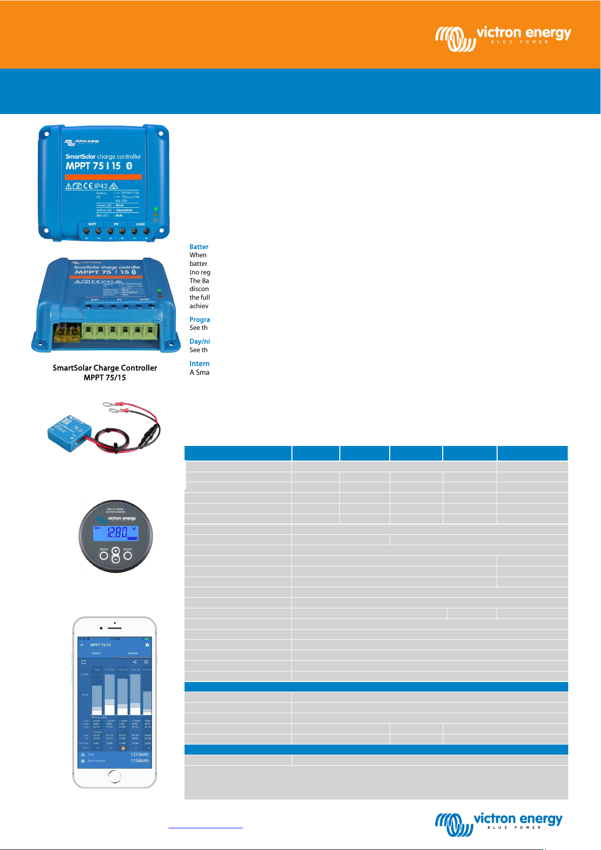
SmartSolar Charge Controllers with load output
SmartSolar Charge Controller
MPPT 75/15
Protection
Battery reverse polarity (fuse) / Output short circuit / Over temperature
IP43 (electronic components),
Bluetooth sensing
Smart Battery Sense
Bluetooth sensing
BMV-712 Smart Battery Monitor
www.victronenergy.com
MPPT 75/10, 75/15, 100/15, 100/20, 100/20_48V
The wireless solution to set-up, monitor, update and synchronise SmartSolar Charge Controllers.
For a wired data connection to a Color Control GX, other GX products, PC or other devices
Especially in case of a clouded sky, when light intensity is changing continuously, an ultra-fast MPPT controller will improve
energy harvest by up to 30% compared to PWM charge controllers and by up to 10% compared to slower MPPT controllers.
Over-discharge of the battery can be prevented by connecting all loads to the load output. The load output will disconnect
the load when the ba ttery has been discharged to a pre-set voltage (48V model: interface with a relay).
Alternatively, an intelligent battery management algorithm can be chosen: see Battery Life.
The load output is short circuit proof.
When a solar charge controller is not able to recharge the battery to its full capacity within one day, the result is oft en that the
battery will continually be cycled between a ‘partially charged’ state and the ‘end of discharge’ state. This mode of operation
(no regular full recharge) will destroy a lead-acid battery within weeks or months.
The Battery Life algorithm will monitor the state of charge of the battery and, if needed, day by day slightly increase the load
disconnect level (i.e. disconnect the load earlier) until the harvested solar energy is sufficient to recharge the battery to nearly
the full 100%. From that point onwards, the load disconnect level will be modulated so that a nearly 100% recharge is
achieved about once every week.
See the software section on our website for details
See the software section on our website for details
A Smart Battery Sense or a BMV-712 Smart Battery Monitor can be used to communicate battery voltage and
temperature to one or more SmartSolar Charge Controllers.
SmartSolar Charge Controller MPPT 75/10 MPPT 75/15 MPPT 100/15 MPPT 100/20 MPPT100/20-48V
Battery voltage 12/24V Auto Select 48V
Rated charge current 10A 15A 15A 20A 20A
Nominal PV power, 12V 1a,b) 145W 220W 220W 290W n. a.
Nominal PV power, 24V 1a,b) 290W 440W 440W 580W n. a.
Nominal PV power, 48V 1a,b) n. a. n. a. n. a. n. a. 1160W
Max. PV short circuit current 2) 13A 15A 15A 20A 20A
General phone: +31 (0)36 535 97 00 | E-mail: sales@victronenergy.com
Automatic load disconnect Yes
Max. PV open circuit voltage 75V 100V
Peak efficiency 98%
Self-consumption 12V: 25 mA 24V: 15 mA 15mA
Charge voltage 'absorption' 14,4V / 28,8V (adjustable) 57,6V (adj.)
Charge voltage 'float' 13,8V / 27,6V (adjustable) 55,2V (adj.)
Charge algorithm multi-stage adaptive
Temperature compensation -16 mV / °C resp. -32 mV / °C
Max. continuous load current 15A 20A 1A
Low voltage load disconnect 11,1V / 22,2V/44,4V or 11,8V / 23,6V/47,2V or Battery Life algorithm
Low voltage load reconnect 13,1V / 26,2V/52,4V or 14V / 28V/56V or Battery Life algorithm
Operating temperature -30 to +60°C (full rated output up to 40°C)
Humidity 95%, non-condensing
Data communication port VE.Direct (see the data communication white paper on our website)
Colour Blue (RAL 5012)
Power terminals 6 mm² / AWG10
Protection category
Weight 0,5 kg 0,6 kg 0,65 kg
Dimensions (h x w x d) 100 x 113 x 40 mm
Safety EN/IEC 62109-1, UL 1741, CSA C22.2
1a) If more PV power i s connected, the controller will limit input power.
1b) The PV voltage must exceed Vbat + 5V for the controller to start.
Thereafter the minimum PV voltage is Vbat + 1V
2) A PV array with a highe r short circuit current may damage the controlle r.
ENCLOSURE
STANDARDS
100 x 113 x 50 mm
IP22 (connection area)
100 x 113 x 60 mm
 Loading...