

Page 1
2017-08-15 16:55 1/7 Energy Meter EM24 manual
Victron Energy - https://www.victronenergy.com/live/
Energy Meter EM24 manual
1. Introduction and usage
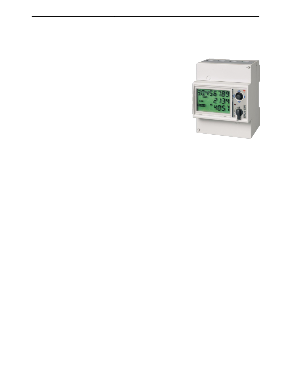
This document is the manual for the EM24 three phase max 65 A per phase Energy Meter. As shown
in the picture above.
Note that this product is no longer sold. Use the ET340 for new installations.
https://www.victronenergy.com/accessories/wired-ac-sensor
The Energy Meter can be used for four things:
Grid meter, and used as control input for an ESS System (1).1.
Measure the output of a PV Inverter2.
Measure the output of a AC Genset3.
(deprecated) Grid meter, used as control input for a Hub-4 system4.
(1) In case the meter is used as a grid meter in a single phase installation, it is possible to use the
second phase to measure the output of a PV Inverter. Note that this does not work properly, use the
ET340 instead. See Energy Meters FAQ, Q5 for details.
The meter is connected to the Color Control GX. There are two options in its wiring:
Direct connection, either using the RS485 to USB interface with 1.8m cable length, or the 5.0m1.
cable.
Wireless connection via Zigbee2.
The REL200100000 is the EM24DINAV93XISX from Carlo Gavazzi. Other EM24 models from Carlo
Gavazzi can also be used, as the communication is the same. For example the EM24DINAV53DISX,
which uses Current Transformers and can therefore work in systems > 63A per phase, has been
tested and works. Note that this model is not stocked by Victron Energy, we recommend to purchase
Page 2
Last update: 2017-07-19 14:55 energy-meters:em24 https://www.victronenergy.com/live/energy-meters:em24
https://www.victronenergy.com/live/ Printed on 2017-08-15 16:55
it locally.
2. AC Wiring and front selector
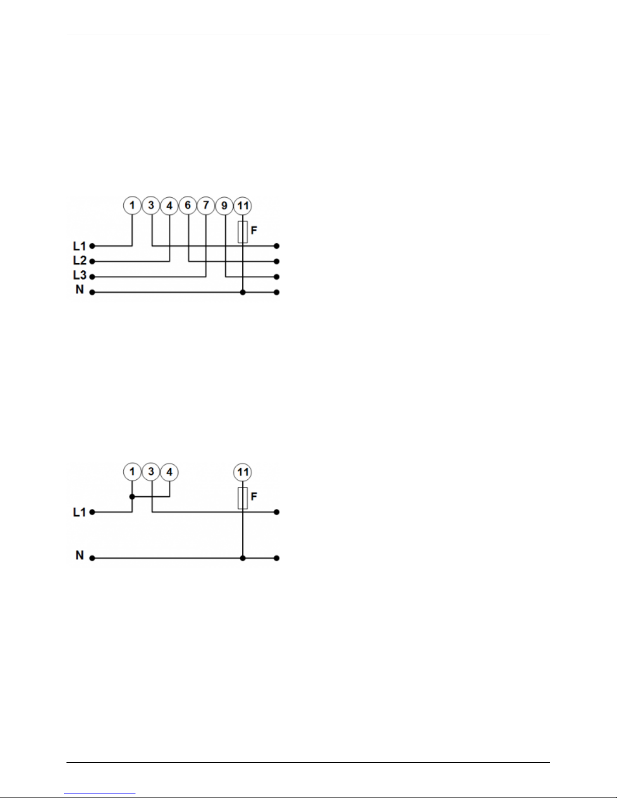
3-phase diagram:
When used to measure a PV Inverter, terminals 1, 4 and 7 should face the PV inverter to ensure
correct direction of current and power.
single phase single function diagram:
Note the jumper between terminals 1 and 4. You do not need this connection if you have the version
AV2 of the sensor:
The diagram shows the wiring when used as a grid meter.
To measure a single phase PV inverter in a 3-phase system, connect all 3 phases to the grid phasing
terminals (3, 6 and 9). Now you can chose on which phase you want the PV inverter by connecting the
L1 line of the PV inverter to terminal 1, 4 or 7.
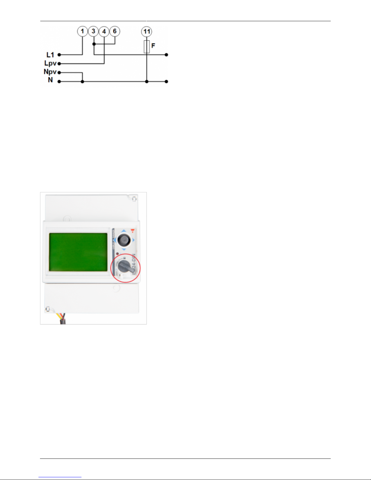
single phase dual function diagram:
In this diagram, a single meter is used to both measure the grid and a single phase PV Inverter.
Page 3
2017-08-15 16:55 3/7 Energy Meter EM24 manual
Victron Energy - https://www.victronenergy.com/live/
On the CCGX go to the grid meter in the Wired AC sensor settings. Make sure 'Phase type' is set to
'Single phase' and 'PV inverter on phase 2' is enabled.
Front selector
Change the front selector so it is not in the locked state. This will allow it to be automatically
configured by the rest of the system the meter. The front selector is located next to the display as
indicated in this image:
3. Connection to CCGX
Option A: wireless Zigbee connection
Step 1.
Connect the Zigbee to USB converter to the CCGX using the supplied USB cable. A few seconds after
connecting, the active LED should be on and the TX/RX LED should be blinking (the converter takes its
Page 4

Last update: 2017-07-19 14:55 energy-meters:em24 https://www.victronenergy.com/live/energy-meters:em24
https://www.victronenergy.com/live/ Printed on 2017-08-15 16:55
power from the CCGX, so the CCGX needs to be switched on as well).
Step 2.
Connect the Zigbee to RS485 converter to the EM24 energy meter:
Zigbee Converter Energy meter
GND Terminal 43
A Terminal 42
B Terminal 41
Step 3.
Make sure only one Zigbee device is powered up right now: the Zigbee to USB converter connected to
the CCGX. Power down all others. If you don't do this, the Zigbee to RS485 converter may be
connected permanently to another Zigbee device.
Step 4.
Page 5

2017-08-15 16:55 5/7 Energy Meter EM24 manual
Victron Energy - https://www.victronenergy.com/live/
Connect the 12V DC power supply to the Zigbee to RS485 converter. When the power is switched on,
check the LEDs again.
Option B: Wired connection to CCGX
Connect the Energy Meter to the CCGX with an USB to RS485 cable (see our price list). The RS485 to
USB interface cable between the CCGX and the Energy Meter can be extended up to 100 meters;
make sure that the extensions of the Data+ (orange) and Data- (yellow) wires form a twisted pair.
RS485 Converter Energy meter
Yellow Terminal 41
Orange Terminal 42
Black Terminal 43
The red, green and brown wire coming out of the USB to RS485 cable are not used
4. Configuration
After proper connection and powering up, the meter will be visible on the CCGX in the Settings →
Energy Meters menu:
Page 6

Last update: 2017-07-19 14:55 energy-meters:em24 https://www.victronenergy.com/live/energy-meters:em24
https://www.victronenergy.com/live/ Printed on 2017-08-15 16:55
The menu lists every meter found. And in the gray box at the right side it shows the configured
function.
After selecting a meter, see its detailed settings:
5. Multiple Energy Meters in one system
There are 3 options to connect multiple Energy Meters:
Each wired to a separate RS485-USB converter. Which are then each plugged into a separate USB1.
socket on the CCGX.
2 meters wired on to one RS485-USB converter. In this case the modbus address of the additional2.
meter needs to be changed, so each is unique. See chapter 6.
Wireless connection: the additional meter is connected to an additional Zigbee to RS4853.
converters. There is then no second Zigbee to USB interface required. It is necessary to change of
the modbus address of one of the AC sensors, see chapter 6.
Besides adding an extra sensor, it is also possible, in a single phase installation, to use the, unused,
Page 7

2017-08-15 16:55 7/7 Energy Meter EM24 manual
Victron Energy - https://www.victronenergy.com/live/
second phase to measure the output of the PV Inverter. See see the AC Wiring chapter in this manual.
6. Changing the modbus address
Press the joystick down until until the display shows 'Pass'. The joystick on the right side on the1.
display, above the front selector).
Press the joystick down again and release immediately.2.
Press the joystick right several times until 'Address' appears. Press the joystick down. Now you can3.
adjust the address by pressing the joystick up and down. Set it to 2.
Press down again. 'Baudrate' appears.4.
Press down again twice. 'Address' appears again.5.
Press right until 'End' appears.6.
Press down. The display now shows measurements again.7.
Note that only one extra Energy meter can be added: the systems works only with address 1 (the
default) and 2.
DISQUS
View the discussion thread.
From:
https://www.victronenergy.com/live/ - Victron Energy
Permanent link:
https://www.victronenergy.com/live/energy-meters:em24
Last update: 2017-07-19 14:55
 Loading...