

Page 1

Printed in U.S.A. Pt. No. 24712 Rev 5 5/04/100M
Sicherungen. Die Zulassungsbestimmungen der
Sicherheitsbehörden machen es erforderlich, daß die Module
abgesichert werden. Die Sicherung muß in die +Input Leitung
geschaltet werden, nicht in die –Input Leitung, da eine
Unterbrechung der –Input Leitung bewirken würde, daß die GateAnschlüsse auf das Spannungspotential der +Input Leitung
ansteigen würden. Dies könnte angeschlossene Module oder Geräte
beschädigen. Sprechen Sie bitte die Vicor Applikationsabteilung
an, dort erhalten Sie Daten zu den richtigen Sicherungen.
Erdung. Um den IEC 950 Klasse I Erdungsforderungen zu
entsprechen, muß die Grundplatte an Erde/Chassis angeschlossen
werden, wenn der Nutzer die Wandler-Grundplatte berühren kann.
Verwenden Sie dieselbe Kabelstärke wie die für das Eingangskabel
Ihres Wandlers angegebene. Siehe Tabelle Seite 3.
Betriebstemperatur. Bei Mega Modulen darf die Außenseite der
Module eine Temperatur von 85 Grad Celsius nicht überschreiten,
bei Mega Modulen Jr. liegt die Grenze bei 100 Grad Celsius.
Weitere Informationen. Das Vicor Applications Manual und
Produkt-Datenblätter enthalten ausführliche Informationen zu
Mega Modulen und Mega Modulen Jr.. Fordern Sie bitte
Unterlagen bei Vicor oder Ihrer nächsten Vicor Vertretung an.
Sicherheits-Vorschriften
8
Vicor France
Tel: +33-1-3452-1830
Fax: +33-1-3452-2830
Vicor Germany
Tel: +49-89-962-439-0
Fax: +49-89-962-439-39
Vicor Hong Kong
Tel: +852-2956-1782
Fax: +852-2956-0782
Vicor Japan
Tel: +81-3-5487-3880
Fax: +81-3-5487-3885
Vicor Italy
Tel: +39-02-2247-2326
Fax: +39-02-2247-3166
Vicor U.K.
Tel: +44-1276-678-222
Fax: +44-1276-681-269
Vicor Corporation
Andover, MA, U.S.A
Tel: 978-470-2900
Fax: 978-475-6715
Sunnyvale, CA
Tel: 408-522-5280
Fax: 408-774-5555
Chicago, IL
Tel: 630-769-8780
Fax: 630-769-8782
Visit the Vicor website at:
www.vicorpower.com
Page 2
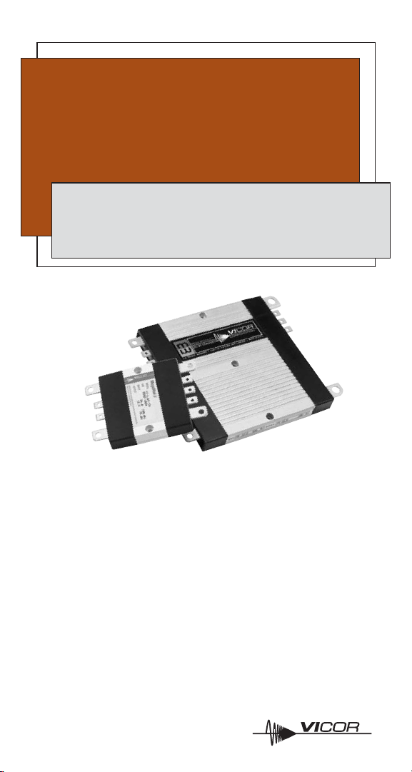
Product Description
MegaMod and MegaMod Jr. DC-DC converters incorporate one,
two, or three Vicor VI-200 or VI-J00 MiniMod converters in a
modular package to provide a chassis-mounted alternative to
board-mounted power supplies. MegaMods offer 50–600 W of
power from 1–3 outputs. MegaMod Jr.’s offer a total of 25–300 W
from 1–3 outputs. Each output may be independently sensed,
adjusted, and sequenced using the procedures outlined for VI-200
and VI-J00 converters in the Vicor Applications Manual.
MegaMod DC-DC
Converter Family
Installation and Application Notes
Functional and Mechanical Layout
Page 3

MegaMod Family
Single Output
LJ-Series 25 –100 W (Jr. Module)
L-Series 50 – 200 W
M-Series 100 – 400 W
N-Series 300–600 W
Dual Output
PJ-Series 50 –200 W (Jr. Module)
P-Series 100 –400 W
Q-Series 150 – 600 W
Triple Output
RJ-Series 75–300 W (Jr. Module)
R-Series 150 –600 W
Materials
■ End Caps: Lexan-920 polycarbonate (UL94V-0)
■ High-Power Terminals: CD-110 copper with electro-tin plate
■ Low-Power Terminals: FR-4, 4 oz. copper with tin plate
■ Case: 6063-T5 aluminum (Case is electrically isolated from
input and output.)
2
Page 4

Fusing. Safety agency conditions of acceptability require
module input fusing. The fuse should be inserted in the +Input
lead, not the –Input lead, since opening the –Input lead will
cause the gate terminals to rise to the voltage of the +Input lead,
which may damage connected modules or devices. Consult the
Vicor Applica tion Engineering Department for proper fuse values.
Grounding. If the converter baseplate is accessible to the
operator, ground the baseplate to earth/chassis ground. Use the
same wire gauge as that specified for your converter’s input
wire, below.
Input Wire Gauge. Calculate the input current for MegaMods
and MegaMod Jr.’s as follows and use the recommended input
wire gauge.
■ I
IN
= P
OUT
/ (η x VLL)
P
OUT
= output power
η = efficiency = 0.8
V
LL
= low line voltage
■ Example:
I
IN
= 300 / (0.8 x 42) = 8.93A
Use a #16 input wire.
Input Source Impedance. The converter should be connected
to an input source that exhibits low AC impedance. If source
impedance is questionable, mount a small electrolytic capacitor
close to the module voltage input pins. This will restore low AC
impedance while avoiding the potential resonance associated
with “high-Q” film capacitors. The minimum value of the
capacitor, in microfarads, should be C(μF) = 400 ÷ V
IN
mini mum.
Example: V
IN
minimum for a VI-260-CV module is 200 V.
The minimum capacitance would be 400 ÷ 200 = 2 μF.
Installation and Application Notes
Input Input Wire
Current Gauge
16.5 A–26.1 A #12
10.4 A–16.4 A #14
6.6 A–10.3 A #16
4.1 A–6.5 A #18
2.6 A–4.0 A #20
0 A–2.6 A #22
(continued on page 6)
3
Page 5

Functional and Mechanical Layout
Inputs
R- and RJ-Series Q-Series N-Series
4
L- and LJ-Series
P- and PJ-Series M-Series
These drawings show MegaMods
(full size). Input and output
configurations for Jr. modules (half
size) are the same where indicated.
Where dimen sions differ for Jr.
modules,
the Jr. measure ments
are in orange
.
1.60
(40,6)
HALF SIZE:
4
1
3
2
TOP V
5.52
(140,2)
2.76
(70,1)
TYP.
0.19
(4,8)
TYP.
2.18
(55,4)
0.16
(4,1)
DC-DC CONVERTER
MEGA MODULE
2
3
1
4
1
3
2
4
5
6
TOP V
DC-DC CONVERTER
MEGA MODULE
5
2.26
(57,4)
2.26
(57,4)
0.19
(4,8)
1
3
2
4
4
8
7
1
2
33
2
1
7
8
4
5
6
TOP VIEW
7
6.94
(176,3)
2.26
(57,4)
2.26
(57,4)
0.19
(4,8)
DC-DC CONVERTER
MEGA MODULE
Mounting Information
Use #6 machine hardware
torqued to 5-7 in-lbs.
Inputs
1 –Input
2 Gate Out #1
3 Gate In #1
4 +Input
5 Gate Out #2
6 Gate In #2
7 Gate Out #3
8 Gate In #3
Outputs
Output #1
A –Output
B–Sense*
C Trim*
D+Sense*
E +Output
Output #2
F –Output
G–Sense*
H Trim*
J+Sense*
K +Output
Output #3
L –Output
M–Sense*
N Trim*
P+Sense*
Q +Output
Page 6

Outputs
All Models
N-Series Q-Series R- and RJ-Series
Ref. Drawing: 10874
5
L- and LJ-Series
M-Series P- and PJ-Series
2.58
(65,5)
JR. MODULE:
SER. NO.
4.90
(124,5)
TYP.
0.53
(13,5)
TYP.
3.20
(81,3)
HALF SIZE:
ø.150 (ø3,81) THRU
C'BORE ø.250 (ø6,35)
X .170 (4,32) DEEP
B
D
A
C
E
0.62
(15,7)
TYP.
TYP.
2,50
(63,5)
TYP.
BASEPLATE
(TYP.)
C
A
D
B
E
E
B
D
A
C
K
G
J
F
H
0.25
(6,4)
TYP.
4.90
(124,5)
TYP.
C
A
D
B
E
H
F
J
G
K
E
B
D
A
C
B
A
C
D
E
P
M
L
N
Q
J
G
K
H
F
7.32
(185,9)
TYP.
SIDE VIEW
* For units
with BatMods
–Sense = I
MON
Trim = I
TRIM
+Sense = V
TRIM
Page 7

Input Transients. Do not exceed the converter’s transient input
voltage rating. Vicor VI-IAM Input Attenua tor Mod ules or
surge suppressors, in combination with appro priate filtering,
should be used in applications where source transients may be
induced by load changes, blown fuses, etc. NOTE: On any
converter module with a high line rating in excess of 250 Vdc,
do not let the rate of change of input voltage exceed 10 V/μs for
any input voltage change in excess of 250 V.
Terminal Connection Assembly. The drawing below illustrates
the assembly of parts for proper power terminal connections.
Please consult the table for the recommended torque level for
each screw size.
Ref. Drawing: 10875
Terminal and Terminal Recommended
Product Model Style Screw Size Torque
–Input, +Input
All models PCB 8-32 UNC 10 in-lb (1.1 N-m)
–Output, +Output
L-, P-, R-, LJ-, PCB 8-32 UNC 10 in-lb (1.1 N-m)
PJ- & RJ-Series
M- & N-Series Metal 1/4-20 UNC 18 in-lb (2.0 N-m)
Q-Series PCB 8-32 UNC 10 in-lb (1.1 N-m)
Metal 1/4-20 UNC 18 in-lb (2.0 N-m)
Supervisory Sized to accept AMP Faston®insulated
All models receptacle #2-520184-2
6
(continued from page 3)
NUT
TERMINAL
LUG
SCREW
HELICAL
LOCKWASHER
Page 8

Output Wire Gauge. Use the output wire gauge that
corresponds to the output current of your converter, below:
105 A–160 A : #4 26 A–40 A : #10 7 A–10 A : #16
66 A–104 A : #6 16 A–25 A : #12 4 A–6 A : #18
41 A–65 A : #8 11 A–15 A : #14 0 A–3 A : #20
Output Voltage Trimming. Do not trim the outputs higher than
110% of their nominal output voltage. When an output is
trimmed up, do not exceed its maximum rated output power.
Operating Temperature. Do not allow the baseplate of the
module to exceed 85°C for MegaMods or 100°C for MegaMod
Jr.’s. The mounting interface area should be flat within 0.005",
free of burrs, and coated with thermal compound (Wakefield
Engineering Type 120 or equivalent, or a thermal pad).
Depending on the power level and ambient temperature,
additional cooling measures may be required. Note: For
configurations using three 12 V input (75 W) or 24 V input
(150 W) modules and operating at ambient temperatures
in excess of 50°C, please consult Vicor’s Applications
Engineering Department.
For More Information
The Vicor Applications Manual and product data sheets contain
complete information about MegaMods and MegaMod Jr.’s.
To receive literature or to consult an applications engineer about
installation or operation of these products, contact your nearest
Vicor office. (See page 8.) Vicor’s Applications Manual is also
available on-line at: vicorpower.com
(Bitte lesen Sie die Sicherheits-Vorschriften auf Seite 8.)
“AMP” and “Faston” are registered trademarks of AMP, Incorporated, Harrisburg, PA.
7
 Loading...