


USER GUIDE | UG:107
3 Phase MegaPACTM 4kW MegaPACTM AC-DC Switcher
August 2013
Contents Page
Overview |
1 |
of Product |
|
Mechanical |
2 |
Considerations |
|
MegaPAC |
3 |
Do’s and Don’ts |
|
Technical Description |
4 |
Configuring and |
5 |
Reconfiguring |
|
MegaPACs |
|
ConverterPAC |
6 |
Description |
|
Part Numbering |
10 |
Quick Install |
12 |
Instructions |
|
Mechanical Drawings |
15 |
Interface Connections |
17 |
Specifications |
24 |
Current Share Boards |
26 |
Low Leakage Version |
29 |
4kW MegaPAC
3 Phase MegaPAC
Overview
The 3 Phase MegaPAC and 4kW MegaPAC are field-configurable, single or multiple output switchers providing up to 2,000 W (3 Phase MegaPAC) to 4,000 W (4kW MegaPAC) of output power. The chassis has 10 slots and can provide up to 40 regulated, fully isolated outputs. It achieves power densities of 4.4 Watts per cubic inch (3 Phase MegaPAC) to 7.8 Watts (4kW MegaPAC) per cubic inch. The dimensions of the 3 Phase MegaPAC are 4.9"H x 7.5"W x 12.3"L (124,5 mm x 190,5 mm x 312,4 mm) and the dimensions of the 4kW MegaPAC are 4.9"H x 7.5"W x 14"L (124,5 mm x 190,5 mm x 355,6 mm). The 4kW MegaPAC is longer than the 3 Phase MegaPAC to
accommodate a 2nd fan.
A complete power supply is configured at the factory by selecting and inserting up to ten same length slide-in output assemblies called ConverterPACs. ConverterPACs incorporate one or two VI-200/VI-J00 and/or Maxi Vicor DC to DC converters and are available in a wide selection of outputs and power levels. The net result is a power supply that offers the advantages of a custom supply, but is assembled from standard and modular building blocks. For detailed information about ConverterPACS, refer to
the ConverterPAC information sheet. The 4kW MegaPAC uses VI-200/VI-J00 and Maxi Vicor DC to DC converters while the 3 Phase MegaPAC uses VI-200/VI-J00 Vicor
DC to DC converters.
Manufactured at Westcor, a division of Vicor, the entire family of MegaPAC power supplies is completely user-configurable. If output requirements change, i.e., more power or a different output voltage is needed, upgrading is easy: simply unlock a single screw and replace the slide-in ConverterPAC with one of the same length and has the desired voltage power rating. For additional flexibility, same length ConverterPACs can be connected in parallel to increase output power (booster ConverterPACs), or in series for higher voltages (total output voltage should not exceed 400V). The driver is to the left of the boosters when looking at the output end of the supply. A user-friendly
interface provides control and output sequencing capability, in addition to useful status indicators. Please consult our Applications Engineering Department if you have other special requirements.
UG:107 |
vicorpower.com |
Applications Engineering: 800 927.9474 |
Page 1 |

Standard Features
n Input: 3Æ 208/240 Vac Wye or Delta, 1Æ 180-264 (47-500Hz) or 260–352 Vdc
n Power Output: |
3 Phase MegaPAC: 2,000W with 3Æ input; 1,200W |
|
with 1Æ input; 1–20 outputs |
|
4kW MegaPAC: 4,000W with 3Æ input; 1,500W |
|
with 1Æ input; 1–20 outputs |
n10 slots (up to 20 outputs)
nFan cooled (the 4kW MegaPAC has 2 fans)
nFull power to 45°C; half power to 65°C
nPower factor correction (passive) 0.92 PF (3Æ input)
nConducted EMI meets EN 55022 Level A
nAC Power OK and AC Power Fail status signals
nOutput Sequencing and General Shutdown
(Consult Applications Engineering for automatic sequencing circuitry.)
nAutosense (Refer to page 11 and page 15 for more information on Autosense)
nOvercurrent protection on all outputs
nOvertemperature limiting (not applicable with VI-J00 modules)
nOutput overvoltage protection (not applicable with VI-J00 modules)
nRide-Through time: >20 ms at nominal line (full load)
nSize: 4 kW MegaPAC: 4.9"H x 7.5"W x 14"L (124,5mm x 190,5mm x 355,6mm) Regular chassis
Size: 3 Phase MegaPAC: 4.9"H x 7.5"W x 12.3"L (124,5mm x 190,5mm x 312,4mm) Regular chassis
nSafety Agency Approvals: CE Mark, UL, CSA, TUV
Optional Features
nDC OK status signal
nOutput voltage adjustment range with built-in potentiometer
nReversed fan airflow direction
nIndustrial-grade screening of output converters
nCurrent Share Boards - See page 27 and 28
Mechanical Considerations
The 3 Phase MegaPAC and 4kW MegaPAC can be mounted on any of four surfaces using standard 8-32 or 4 mm screws. The chassis comes with four mounting points on each surface; maximum allowable torque is 20 lb-in.
The maximum penetration is 0.15 in. (3,8 mm).
When selecting a mounting location and orientation, the unit should be positioned so air flow is not restricted. Maintain a 2" minimum clearance at both ends of the 3 Phase MegaPAC and 4kW MegaPAC and route all cables so airflow is not obstructed. The standard unit draws air in at the fan side/AC input side and exhausts air out the load side. If airflow ducting is used, use caution, as sharp turns could present back pressure to the 3 Phase MegaPAC and 4kW MegaPAC. The fans move approximately 50 CFM of air for the 4kW MegaPAC and 30 CFM for the 3 Phase MegaPAC. The 4kW MegaPAC has a second fan for additional cooling capabilities.
UG:107 |
vicorpower.com |
Applications Engineering: 800 927.9474 |
Page 2 |

Avoid excessive bending of output power cables after they are connected to the 4kW MegaPAC or 3 Phase MegaPAC. For high-current outputs, use cable ties to support heavy cables in order to minimize mechanical stress on output studs. Be careful not to shortout to neighboring output studs. The 3 Phase MegaPAC and 4kW MegaPAC is supplied with serrated, flanged hex-nuts on all output studs, so thread locking compounds or lock washers are not required. The maximum torque recommended on flanged nuts is 45 lbin. Never loosen the inner nut on a ConverterPAC. This nut supports the hardware inside the ConverterPAC and is factory torqued.
Avoid applications in which the unit is exposed to excessive shock or vibration levels. In such applications, a shock absorption mounting design is required.
MegaPAC Do’s and Don’ts
nFor units without Autosense, do not leave ConverterPAC Sense lines open. Always terminate them at their respective outputs locally or at the load. Use twisted pair 22-24 AWG wire. If ConverterPAC has Autosense, no local sense connection is required. See page 13 and 17 for more information on Autosense.
nIf needed, use Connector Kit # 19-130041 for the 3 Phase/4kW MegaPACs.
nAlways fill all output slots of the MegaPAC. If a slot is not filled with a ConverterPAC, it should be filled with an airblock. Airblocks are plastic assemblies whose main function is to fill up an empty slot. Any airflow escape from an empty slot, significantly degrade thermal performance can result in overheating and damage to the power supply.
nDo not unplug ConverterPACs while input power is applied. They are not designed for hot-plug applications.
nDo not restrict airflow to the unit. Leave 2 inch minimum space in front and behind the supply. The cooling fan draws air into the unit and forces it out at the output power terminals.
nFor power expansion, use booster ConverterPACs. Viewing the unit from the output terminal side, always insert boosters to the right side of the driver.
nDo not use boosters as independent outputs. Disconnecting bus bars will damage booster ConverterPACs.
nAlways ensure that output hex-nuts arer properly torqued before applying power to supply.
nFor booster arrays, do not remove busbars.
nRun the output (+/–) power cables next to each other to minimize inductance.
nWait 5 minutes after shutting off power before inserting or removing ConverterPACs.
nThe MegaPACs does not have user serviceable components. They must be returned to the factory for repairs. Contact Customer Service for a RMA number before returning the unit. Do not attempt to repair or modify the power supply in any manner other than the exchange of ConverterPACs as described in this User Guide.
nInsert proper fault protection at power supply input terminals (i.e., a fuse).
nUse proper size wires to avoid overheating and excessive voltage drop.
nNever loosen the inner nut on a ConverterPAC.
nVerify output nuts are tight before powering up.
nOnly use the regular length ConverterPACs in the 3 Phase/4kW MegaPAC chassis. You cannot use any of the Extended Length ConverterPACS which are only used in the EL (Low Noise) products.
nKeep in mind that currently, the UniPAC ConverterPAC can only be used in the 4kW MegaPAC.
UG:107 |
vicorpower.com |
Applications Engineering: 800 927.9474 |
Page 3 |
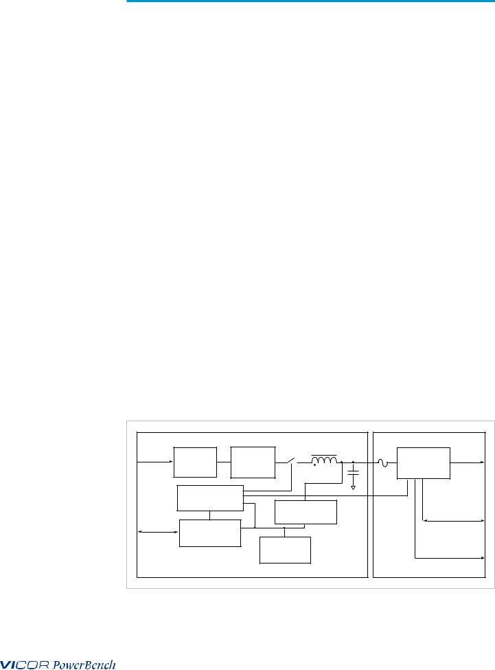
Figure 1.
3 Phase MegaPAC and 4kW MegaPAC Architectures
Technical Description
The 3 Phase MegaPAC and 4kW MegaPAC are configured by installing same length ConverterPAC assemblies into the chassis. The chassis takes AC input power and performs filtering and rectification functions. The ConverterPACs plug into a highvoltage backplane and provide low-noise, independently regulated and fully isolated outputs.
Input AC mains voltage (L1, L2, L3 and GND) is applied to an agency approved mating plug. The input current is passed through an EMI filter designed to meet EN 55022 Level A before it is passed to a three-phase full-wave bridge rectifier. The rectifier charges storage capacitors and delivers unregulated 300 Vdc to a backplane after passing through a large choke that improves input power factor. The power factor typically exceeds 0.9 depending upon load, line voltage, frequency and line balance. Inrush current is actively controlled with an IGBT and never exceeds 30A peak regardless of hot or cold starts.
A housekeeping supply, isolated from the AC input, powers the brushless DC cooling fan and other input monitoring circuits, in addition to providing an auxiliary +5V power source for the user. The 4kW MEGAPAC HAS A SECOND FAN FOR EXTRA COOLING. Excessive input currents caused by loss of a phase or excessive output loading in single phase operation will safely shut down the unit until input power is recycled. This occurs when the peak input current reaches 30A . An analog temperature monitor is provided, as well as overtemperature shutdown. An active-high TTL compatible Enable control is included for each ConverterPAC assembly, as well as an active-low General Shutdown control; the polarities, active-high or active-low, are factory set. The 3 Phase MegaPAC and 4kW MegaPAC can be safely paralleled (with another of its own kind) with accurate current sharing for high power systems. All interface signals are safety isolated using a common floating return.
Upon power-up, all outputs are first disabled to limit the inrush current, and to allow the unregulated bus to reach correct operating levels for ConverterPAC assemblies. The internal housekeeping supply comes up within 500 ms after input power is applied, and the AC Power OK signal asserts to a TTL "1," indicating the input power is OK. The low voltage power outputs come up within 10-20 ms after the AC Power OK asserts to a TTL "1." Output ramp-up time from Enable or General Shutdown is 10-20 ms. Output fall time from Disable is dependent on load, but is typically a few hundred microseconds.
J1 |
|
|
|
|
|
|
+P, -P |
Input |
|
|
|
IGBT |
PFC Choke |
|
Output |
Power |
EN 55022 |
|
3 Phase |
Fuse |
Power |
||
|
|
|
|
|
DC/DC |
||
|
Level A |
Full-Wave |
|
|
|||
|
|
|
Converter |
||||
|
|
|
Rectifier |
|
|
|
|
|
|
|
|
|
|
|
|
|
Start-up Control |
|
|
|
|
|
|
|
Circuits |
|
|
Isolated |
|
Remote Sense, |
|
J10 |
|
|
|
|
|||
|
|
|
Housekeeping |
|
Trim Interface |
||
Customer |
|
|
|
Power Supply |
|
|
|
Interface |
Opto-isolated |
|
|
|
|
|
|
|
|
|
|
|
|
|
|
|
Control/Status |
|
|
|
|
|
Power Good |
|
|
|
|
DC Brushless |
|
|
|
|
|
|
|
|
|
Interface |
|
|
|
|
|
Cooling Fan |
|
|
|
|
|
|
|
|
|
|
|
3 Phase/4kW MegaPAC Chassis |
|
|
|
ConverterPAC (Up to 10) |
|||
UG:107 |
vicorpower.com |
Applications Engineering: 800 927.9474 |
Page 4 |

Figure 2.
Paralleling ConverterPACs
Configuring and Reconfiguring MegaPACs
Most ConverterPACs of the same length can be easily added, replaced, or moved by sliding the assemblies in or out of a MegaPAC chassis. They are driver ConverterPACs and can be inserted into any available slot. For outputs greater than 200 Watts, a driver ConverterPAC and one or more booster ConverterPACs will be used. For outputs greater than 500 Watts (in the 4kW MegaPAC), a driver UniPAC and one or more booster UniPACs will be used. Arrays of drivers and boosters should be configured so all boosters are placed in the slots to the immediate right of the driver when looking at the output end of the MegaPAC.
Prior to removing or installing ConverterPACs, you must remove power from the MegaPAC and wait 5 minutes. Failure to do so can result in personal injury or damage to the supply.
Take standard ESD precautions when handling ConverterPACs.
Removing ConverterPACs
ConverterPACs can be removed by loosening the captive screw at the base. Once this screw has been loosened, the ConverterPAC will slide out of the chassis. Once a ConverterPAC has been removed, the empty slot MUST be filled with either another ConverterPAC of the same length or an airblock. If the slot is left empty, it will provide an airflow escape and cause failure to the power supply.
Installing ConverterPACs as Drivers
ConverterPACs can be installed in empty slots by simply sliding in the new ConverterPAC and securing the screw at the base. Power and interface connections can be made after the ConverterPAC has been installed.
Installing Booster ConverterPACs to Increase Output Power
ConverterPACs can be paralleled for more power. Additional power to an output is obtained by connecting one or more boosters in parallel with a single driver. The driver can be placed in any open slot. All boosters should be inserted in the slots to the immediate right of the driver, as viewed from the output end of the MegaPAC. Figure 2 shows a driver placed in slots #1 and 3 boosters placed in slots # 2 to 4. After inserting the driver and boosters, they are paralleled using bus bars across the positive and negative output studs. Drivers should not be paralleled with each other. Bus bars between a driver and booster(s) should never be disconnected. For help in identifying boosters and drivers, refer to the Part Numbering section on page 10. Please note that
total output voltage should not exceed the converter baseplate-output isolation rating of 400V. For detailed guideline on how outputs should be placed in series, please refer to the Applications note available on the website at www.vicorpower.com.
Bus Bars for Paralleling |
|
|
|
|
|
|
|
|
|
|
|
|
Loosen screw to |
|
|
|
|
|
|
|
|
|
|
remove ConverterPAC |
|
|
|
|
|
|
|
|
|
|
|
|
1 |
2 |
|
3 |
4 |
5 |
6 |
7 |
8 |
9 |
10 |
|
Driver |
L1 |
L2 |
L3 |
|
|
|
|
|
|
|
|
Boosters: Slots 2, 3, 4 |
|
|
|
|
|
|
|
|
|
|
UG:107 |
vicorpower.com |
Applications Engineering: 800 927.9474 |
|
Page 5 |
|||||||
VI-200
VI-J00

 +
+

 _
_
ModuPAC

 +
+

 _
_
JuniorPAC
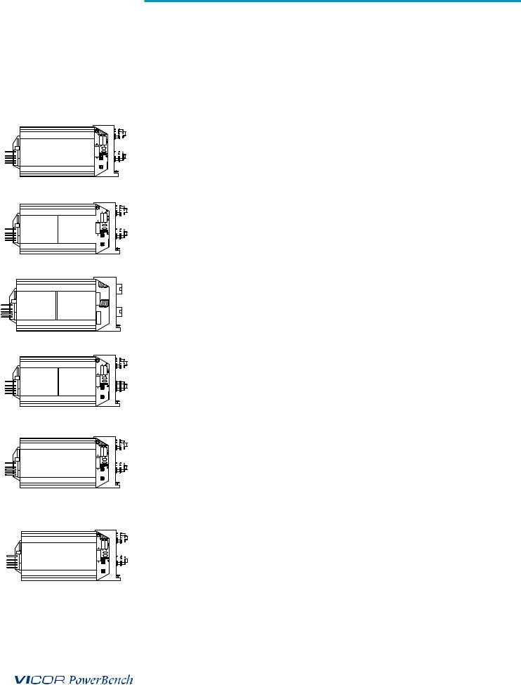
ConverterPAC Functional Description
ConverterPACs are the family of slide-in output assemblies used in MegaPAC power supplies. Most ConverterPACs of the same length are interchangeable within a MegaPAC or between different AC input chassis. They can be added, moved, or changed as necessary. The following ConverterPACs can be used in the 3 Phase and 4kW MegaPACs.
ModuPAC
The ModuPAC output assembly consists of a VI-200 Vicor DC to DC converter that converts the unregulated high voltage bus to the desired regulated output voltage. Each ModuPAC can provide up to 200 Watts of power. Multiple ModuPACs can be paralleled in a driver-booster configuration to provide more power.
JuniorPAC
The JuniorPAC consists of a VI-J00 Vicor DC to DC converter that converts the unregulated high voltage bus to the desired regulated output voltage. JuniorPACs can provide up to 100 Watts of output power.
M1
VI-J00 VI-J00
M2
M2 M1
DualPAC

 +
+
VI-J00 |
RAM |
_ |
RAMPAC
DualPAC
This output assembly consists of two VI-J00 Vicor DC to DC converters that convert the unregulated high voltage bus to the desired regulated output voltages.
RAMPAC
This output assembly consists of a VI-J00 Vicor DC to DC converter with a Ripple Attenuator Module (RAM) and is designed for applications requiring low output ripple/ noise.
VI-200/BatMOD
Maxi

 +
+

 _
_
BatPAC

 +
+

 _
_
UniPAC
BatPAC
The BatPAC output assembly consists of a VI-200 BatMod current source that converts the unregulated high voltage bus to the desired regulated output voltage. The BatPAC is a 200 Watts programmable current source that can be configured as a battery charger.
UniPAC
The UniPAC output assembly consists of a Maxi Vicor DC-DC module that converts the unregulated high voltage bus to the desired regulated output voltage. UniPACs can provide up to 500W of power. Multiple UniPACs can be paralleled in a driver-booster configuration to provide more power. The UniPAC can only be used in the 4kW
MegaPAC (not in the 3 Phase MegaPAC or any other MegaPACs).
UG:107 |
vicorpower.com |
Applications Engineering: 800 927.9474 |
Page 6 |

ConverterPAC Functional Description (Cont.)
|
FlexPAC |
|
|
|
|
|
|
|
|
The FlexPAC output assembly consists of from 2 to 4 discrete outputs that convert the |
|||||||
|
high output bus to the desired output voltage. Each FlexPAC output can be manually |
|||||||
|
trimmed from 2V to 25V and supports up to 5 amps with a maximum output powerof |
|||||||
|
50W per output. All outputs maintain less than 50mV noise over the entire output |
|||||||
FlexPAC |
range. All outputs support local sense only. For electrical trim options and specific |
|||||||
output sequencing contact the factory |
|
|
|
|
||||
|
List of ConverterPACs used in the 3 Phase/4kW MegaPACs and their features |
|||||||
|
ConverterPAC |
OVP |
OCP |
OTL |
RS/AS* |
LS/AS* |
PG |
TrimPot |
|
ModuPAC |
Std |
Std |
Std |
AS* |
AS* |
Opt |
Opt |
|
JuniorPAC |
N/A |
Std |
N/A |
AS* |
AS* |
Opt |
Opt |
|
DualPAC |
N/A |
Std |
N/A |
AS* |
AS* |
N/A |
Opt |
|
RAMPAC |
N/A |
Std |
N/A |
AS* |
AS* |
Opt |
Opt |
|
BatPAC |
N/A |
Std |
N/A |
N/A |
N/A |
N/A |
Std |
|
UniPAC** |
Std |
Std |
N/A |
AS* |
AS* |
Opt |
Opt |
*See page 13 and 17 for more information on Autosense.
**Currently, the UniPAC (XU) can only be used in the 4kW MegaPAC.
OVP |
Overvoltage Protection (latching) |
OCP |
Overcurrent Protection (auto-recovery) |
OTL |
Overtemperature Limiting (latching) |
RS |
Remote Sense |
PG |
Power Good (DC OK TTL Signal) |
LS |
Local Sense |
|
|
AS |
Autosense |
Note: All ConverterPACs mentioned above can be paralleled EXCEPT the DualPAC,
JuniorPAC and RamPAC.
UG:107 |
vicorpower.com |
Applications Engineering: 800 927.9474 |
Page 7 |
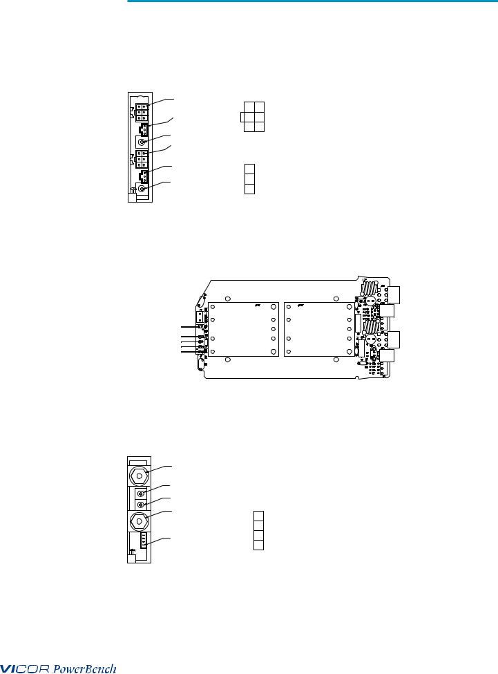
ConverterPAC Output and Connector Pin Identification for the 3 Phase/4kW MegaPACs
DualPAC |
|
J1 |
(OUTPUT CONNECTORS) |
MATING HDWR: |
|
J1-B-PIN1 |
|
|
|
||
|
|
|
1 AND 4 +V OUT |
|
|
|
J2-B-PIN1 |
4 |
1 |
HOUSINGMOLEX P/N: 39-01-2060 |
|
|
5 |
2 |
2 AND 5 -V OUT |
TERMINALSMOLEX P/N: 39-00-0039 |
|
|
|
||||
|
OUTPUT ADJUST |
6 |
3 |
3 +R/SENSE 6 -R/SENSE |
CRIMP TOOL MOLEX P/N: 11-01-0197 |
|
|
|
|
||
|
|
|
|
|
|
|
J1-A-PIN1 |
|
|
|
|
|
|
J2 |
(REMOTE SENSE) |
MATING HDWR: |
|
|
|
|
|
|
|
|
J2-A-PIN1 |
1 |
|
TRIM PIN ACCESS |
HOUSINGMOLEX P/N: 50-57-9403 |
|
|
|
|||
|
OUTPUT ADJUST |
2 |
|
+ SENSE |
TERMINALSMOLEX P/N: 16-02-0103 |
|
|
3 |
|
- SENSE |
CRIMP TOOL MOLEX P/N: 11-01-0208 |
DUALPAC - COMPONENT SIDE VIEW
M2 |
M1 |
J1-B (M1) |
Output A |
Output B |
|
48V/2.1A |
12V/8.3A |
J1-A (M2) |
|
|
Example: D12V/8.3A-48V/2.1A
BatPAC |
|
|
|
|
+ V0UT |
|
|
|
|
CURRENT LIMIT ADJUST |
|
|
|
|
VOLTAGE LIMIT ADJUST |
J2 |
(BATPAC REMOTE INTERFACE) |
MATING HDWR: |
|
- VOUT |
|
|
|
|
4 |
|
CURRENT LIMIT ADJUST |
HOUSINGMOLEX P/N: 39-01-0043 |
|
|
|
|||
|
3 |
|
VOLTAGE LIMIT ADJUST |
TERMINALSMOLEX P/N: 30-00-0031 |
J2-PIN1 |
2 |
|
CURRENT MONITOR |
CRIMP TOOL MOLEX P/N: 57005-5000 |
|
1 |
- VOUT |
|
|
UG:107 |
vicorpower.com |
Applications Engineering: 800 927.9474 |
Page 8 |
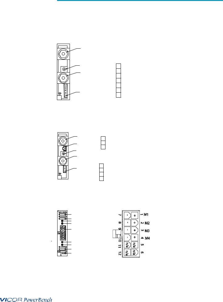
ConverterPAC Output and Connector Pin Identification for the 3 Phase/4kW MegaPACs (Cont.)
UniPAC |
|
|
|
+ V0UT |
|
|
|
|
P2 REMOTE SENSE TRIM/SC & POWER GOOD |
||
OUTPUT ADJUST |
7 |
+SENSE |
MATING HDWR: |
- VOUT |
6 |
-SENSE |
HOUSINGMOLEX P/N: 39-01-0073 |
5 |
|
||
|
TRIM |
TERMINALSMOLEX P/N: 39-00-0031 |
|
|
4 |
Vcc IN |
CRIMP TOOL MOLEX P/N: 57005-5000 |
|
3 |
POWER GOOD |
|
P2-PIN1 |
2 |
POWER GOOD INVERTED |
|
1 |
|
||
|
SIGNAL GROUND |
|
|
ModuPAC |
|
J2 |
(REMOTE SENSE) |
MATING HDWR: |
|
+ V0UT |
|
|
|||
JuniorPAC |
1 |
TRIM PIN ACCESS |
HOUSINGMOLEX P/N: 50-57-9403 |
||
|
|||||
RamPAC |
J2-PIN1 |
2 |
+ SENSE |
TERMINALSMOLEX P/N: 16-02-0103 |
|
|
|
|
CRIMP TOOL MOLEX P/N: 11-01-0208 |
||
|
0UTPUT ADJUST |
3 |
- SENSE |
||
|
|
|
|
||
|
- VOUT |
J3 DC OK (POWER GOOD) |
|
||
|
|
|
|||
|
|
4 |
Vcc IN |
MATING HDWR: |
|
|
J3-PIN1 |
|
|||
|
3 |
POWER GOOD |
HOUSINGMOLEX P/N: 39-01-0043 |
||
|
|
|
|||
|
|
2 |
POWER GOOD INVERTED |
TERMINALSMOLEX P/N: 30-00-0031 |
|
|
|
CRIMP TOOL MOLEX P/N: 57005-5000 |
|||
|
|
1 |
SIGNAL GROUND |
||
|
|
|
|||
FlexPAC |
M-1 STATUS |
|
|
|
|
|
|
|
M-2 STATUS |
|
|
|
M-1 VOLTAGE ADJUSTMENT |
|
|
|
M-2 VOLTAGE ADJUSTMENT |
MATING HDWR: |
|
|
|
|
|
|
CONNECTOR |
J1 |
HOUSING MOLEX P/N 39-01-2120 |
|
|
|
TERMINALS MOLEX P/N 39-00-0039 |
|
|
|
CRIMP TOOL MOLEX P/N 11-01-0197 |
M-3 VOLTAGE ADJUSTMENT
M-4 VOLTAGE ADJUSTMENT
M-3 STATUS
M-4 STATUS
Note: The UniPAC can ONLY be used in the 4kW MegaPAC.
UG:107 |
vicorpower.com |
Applications Engineering: 800 927.9474 |
Page 9 |

Part Numbering
3Ø MegaPAC |
MPx1-5x2xxxx |
|
eg. MP4-510108 |
MP = MP
x1 = number of outputs
9 = 3 Phase MegaPAC chassis x2 = number of modules xxxx = assigned by Westcor
4kW MegaPAC |
MPx1-4x2xxxx-x3x4-x5-x6 |
With VI-200/VI-J00 |
eg. MP10-410008-23 |
With Maxi |
eg. MX10-410008-23 |
MP = MP
x1 = number of outputs 4 = 4kW MegaPAC chassis x2 = number of modules
xxxx = assigned by Westcor
x3 = Optional Code 2 = VI-J00 or VI-200 module in slot #1; 3 = Maxi in Slot 1 x4 = Optional Code 2 = VI-J00 or VI-200 module in slot #10; 3 = Maxi in Slot 10 x5 = Optional Code
x6 = Optional Code
ConverterPAC |
XxDV/xEAxF |
|
eg. M15V/10A |
|
eg. M15V/10ADF |
|
eg. D15V/6.7A-12V/8.3AT |
X = ConverterPAC type - If RoHS precede with a “G” |
|
|
||
M = ModuPAC |
D = DualPAC |
R = RamPAC |
J = JuniorPAC |
B = BatPAC |
XU = UniPAC (currently only used in the 4kW MegaPAC) xD = Voltage out
xE = Current out (rounded to 1 decimal point) xF = Can be multiple options* (see below)
UG:107 |
vicorpower.com |
Applications Engineering: 800 927.9474 |
Page 10 |
 Loading...