

Page 1
Javelin III Power Supply Operator’s Manual
III Power Supply
Power Factor Corrected AC-DC Switcher
Operator’s Manual
and
“Quick Install” Instructions
www.mpwrs.com
Rev. 05/11/2012 Mission Power Solutions (760) 631-6846 sales@mpwrs.com Pg.1
Page 2
Javelin III Power Supply Operator’s Manual
Javelin III Power Supply
AC-DC Switcher
Javelin III Power Supply “Quick Install” Instructions
Mounting the Javelin III Power Supply
The Javelin III can be mounted at either of two surfaces (top or bottom).
Use #8-32 mounting screws. Maximum penetration should not exceed
0.21″ (5.33mm).
Maintain 2” (50,8mm) clearance at either end for airflow.
Input Connections
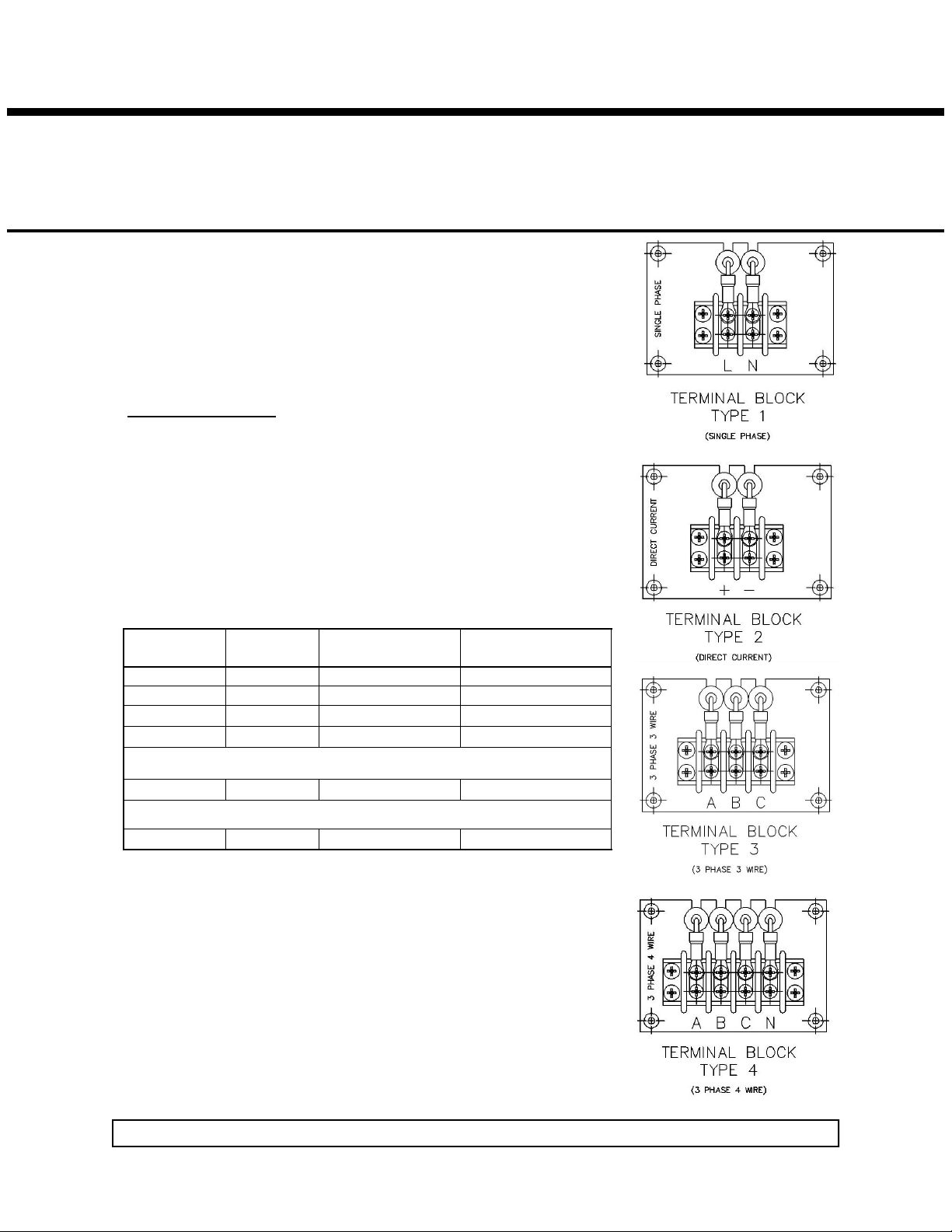
Input Barrier Strip (TB1)
Input AC or DC power is applied to barrier strip TB1. See Table 1 for
single phase, DC, 3 phase/3 wire, or 3 phase/4 wire.
To connect, use #8 ring lugs with 30A rating.
Grounding stud provided for ground connection(s) to the right of TB1.
A fault-clearing device, such as a fuse or circuit breaker, with a maxi-
mum rating per Table 1 at the power supply input is required for
safety agency compliance.
1
Single Phase
TB1-1 L1 TB1-1 + TB1-1 A TB1-1 A
TB1-2 L2/N TB1-2 – TB1-2 B TB1-2 B
30A AC 30A DC 17A AC per phase 10A AC per phase
45A 45A 25A per phase 15A per phase
Table 1. AC and DC Input Connections
2
DC
Current Requirements
Maximum Fuse Rating
3 Phase/3 Wire
TB1-3 C TB1-3 C
3
4
3 Phase/4 Wire
TB1-4 N
Rev. 05/11/2012 Mission Power Solutions (760) 631-6846 sales@mpwrs.com Pg. 2
Page 3
1= TTL High or Open Circuit
0= TTL Low or Closed Circuit
X= Don’t Care
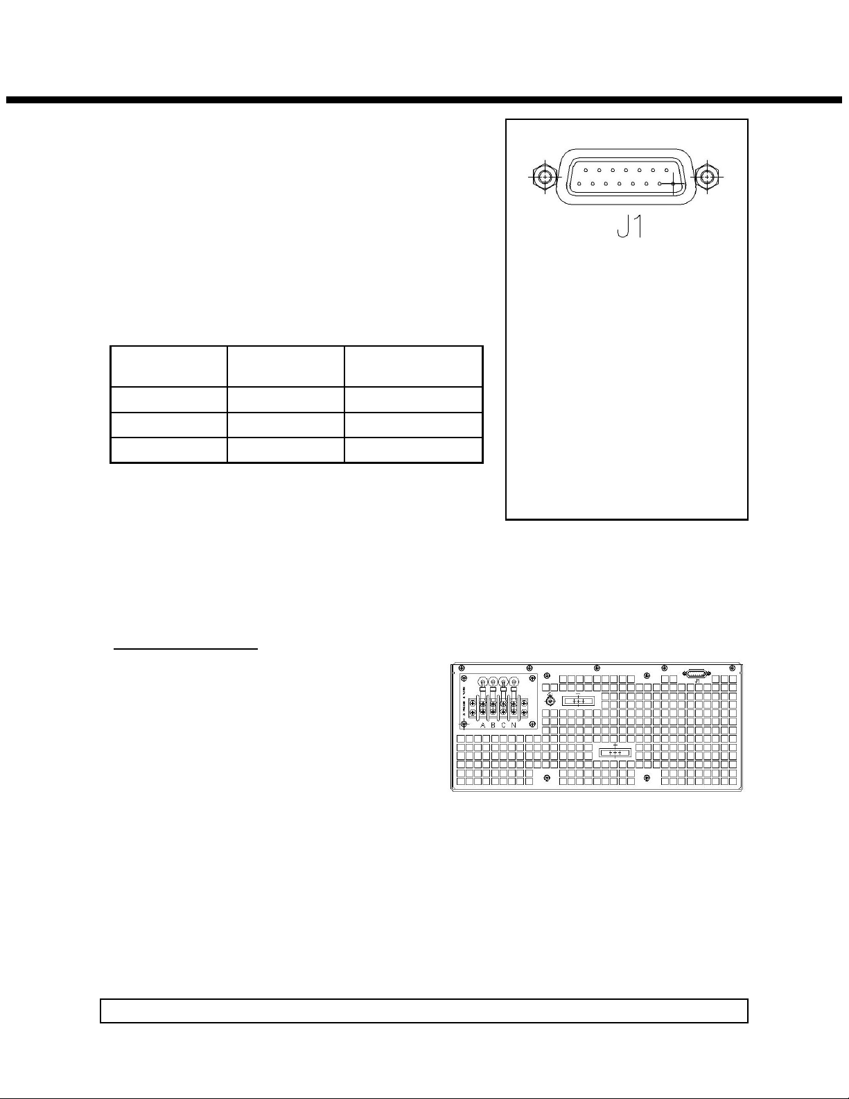
Status/Control/Sense Connector (J1)
J1-1 and J1-9 are Signal Return pins.
J1-2 is VCC +5V @ 300mA.
J1-3 is AC Power OK (+5V = True).
J1-4, 5 and 12 are not connected
J1-5 is +12V fan power.
J1-6 is +5V DC (in).
J1-7 is DC OK and J1-8 is DC OK′.
J1-10 and J1-11 are used in conjunction according to Table 2.
J1-13 is +Remote Sense and J1-14 is –Remote Sense.
J1-11
INHIBIT′
1 X ON
0 0 ON
0 1 OFF
J1-10
ENABLE′
POWER SUPPLY
STATE
Javelin III Power Supply Operator’s Manual
15
8
J1-1 Signal Return
J1-2 VCC +5V @ 300mA
J1-3 AC Power OK
J1-4 N/C
J1-5 N/C
J1-6 +5VDC (in)
J1-7 DC OK
J1-8 DC OK′
J1-9 Signal Return
J1-10 PS Enable′
J1-11 PS Inhibit′
J1-12 N/C
J1-13 +Remote Sense
J1-14 −Remote Sense
J1-15 +5VDC Return (in)
9
1
Table 2. Inhibit/Enable Logic Table
Use ITT/Cannon mating connector P/N DE15PK87.
Use 20-24 AWG stranded wire.
Output Connections
Installing ring lugs on output bus bars:
When viewed from the rear, the upper left output lug
is Return and the lower right output lug is Positive.
Place ½” or smaller bolt through output lug and ring
lugs from load cables and install retaining nut.
Tighten the nut to a torque of 10 ft/lbs.
Sense Connections
The Javelin III is equipped with Auto-Sense (load sensed at output lugs if remote sense is not connected).
Connector pin J1-13 is the +Remote Sense and J1-14 is the –Remote Sense.
If Remote Sense is desired, connect pin J1-13 to the positive load connection and pin J1-14 to the negative
load connection at the point where regulation is desired.
Attach sense terminals to load using 20-24 AWG stranded, twisted pair wire.
Verify that sense lines are not cross-connected.
Rev. 05/11/2012 Mission Power Solutions (760) 631-6846 sales@mpwrs.com Pg. 3
Page 4

Javelin III Power Supply Operator’s Manual
III Power Supply
Power Factor Corrected AC-DC Switcher
Overview
The Javelin III is a ruggedized, switching power supply that combines the advantages of power factor correction and power density with user-selectable output voltage and power. Accepting input voltages of 85 to 254
VAC and 85 to 380 VDC, the Javelin III can provide up to 5400 watts in a 7.00”H x 16.0”W x 13.0”L package.
Its inherent flexibility comes from its use of Vicor 2nd Generation DC-DC converters. Javelin III has three 90
CFM fans for cooling.
Standard Features
Power Factor Correction: .99 at 115 VAC; .95 at 230 VAC.
Universal Input: 85-254 VAC, 47-500 Hz, or 85-380 VDC.
Power Output: Approximately 5400W at 230 VAC for selected outputs; 2400W at 115 VAC. See Graph
1(Pg. 11) for breakdown of input voltage vs. output power.
Full power to 55C; half power at 70C. See Graph 2 (Pg. 12)
Soft start for limiting inrush current.
EMI Compliance: FCC Class A & EN 55022 Class B; MIL-STD-461E.
Transient Protection: MIL-STD-704E.
Environmental: MIL-STD-810E.
MIL-STD-1399 (300A); 115VAC, 60Hz, Single Phase; ≥1KVA<5KVA.
Harmonic Distortion to EN61000-3-2.
AC Power OK status signal.
Fan cooled.
Equipped with Auto-Sense.
Output overcurrent, overvoltage and overtemperature protection.
Ride-through (holdup) time: 20 ms at 3600W load.
Size: 7.00”H x 16.0” W x 13.0”L.
Heavy-duty “ruggedized” enclosure designed for a high shock and vibration environment.
Extra cooling provided for higher output with increased altitude capability.
“D” shell connector for interface connections.
Optional conformal coating for PCBs.
Rev. 05/11/2012 Mission Power Solutions (760) 631-6846 sales@mpwrs.com Pg. 4
Page 5

Javelin III Power Supply Operator’s Manual
Technical Description
The Javelin III consists of an off-line single phase or three phase power-factor-corrected front end (or optional
DC), with EMI filter, cooling fans, customer interface, associated housekeeping circuits, and a selection of Vicor’s DC-DC converters. Three power supply units are placed in parallel to provide the final output current
capability.
Input AC mains (or DC) voltage is applied to a 2-, 3-, or 4-pin power terminal strip (see Table 1, Pg. 2). The
input current is passed through three individual EMI filters designed to meet conducted noise limit “A” specification of FCC Part 15 and EN55022 level “B.”
At start-up, inrush current is limited in each power supply unit by a PTC thermistor. The PTC is shunted out
shortly after initial power-up by a DC bus voltage sense circuit driving a thyristor. After rectification, the input
voltage is applied to a boost converter that keeps the AC input current sinusoidal and synchronized with the
input AC voltage (in compliance with EN61000-3-2). The boost converter delivers a regulated input to the
hold-up capacitors and a high voltage backplane. The backplane supplies power to the DC-DC converters that
provide the desired low voltage, regulated output.
Voltage conversion is achieved by Vicor’s family of Zero-Current-Switching (ZCS) DC-DC converters. These
are forward converters in which the main switching element switches at zero current. This patented topology
has a number of unique attributes: low switching losses, high frequency operation (resulting in reduced size for
magnetics and capacitors), excellent line and load regulation, wide output adjustment range, low EMI/RFI
emission, and high efficiency.
At initial power-up, the Javelin III output is disabled to limit the inrush current and to allow the DC bus potential to settle out to the correct operating level. A low-power flyback converter operating with PWM currentmode control converts the high voltage DC bus into regulated low voltage to power the internal housekeeping
circuits and DC cooling fans.
The internal housekeeping Vcc comes up within 1 second after the application of input power. Once the high
voltage bus is within operating limits, the AC Power OK signal changes its output to a TTL “1,” which indi-
cates the input power is OK and allows the power output to come up 15-30 ms later. An auxiliary Vcc output
of 5VDC, capable of sourcing up to 300mA, is provided for peripheral use.
An output Inhibit/Enable function is provided by using an optocoupler to control Vicor’s DC-DC converters. If
the Inhibit control pin is pulled low and the Enable pin is high or open, the optocoupler will turn on and disable
the output. The delay for an output to come up when measured from release of the Enable pin is 5-10 ms. See
Table 2 (Pg. 3) for a logic table.
To utilize trim capabilities, consult Mission Power Solutions’ Engineering Department.
Rev. 05/11/2012 Mission Power Solutions (760) 631-6846 sales@mpwrs.com Pg. 5
Page 6

Power
Output
Line Filter
Rectifier
Soft Start
Circuit
Boost Converter
Output
PFC Control
Customer
Interface
I/E Control
Fan
Housekeeping
Power
Input
Current
Sample
Waveform
Sample
Inhibit/Enable Control
Inhibit/Enable
Interface Connections
Javelin III Power Supply Operator’s Manual
Figure 1. Javelin III Architecture
Input Power Terminal (TB1)
Input AC (and DC) Power is applied to connector TB1 using a #8 ring lugs. See Table 1 (Pg. 2) for input connector assembly instructions.
A fault-clearing device, such as a fuse or circuit breaker, with a maximum rating per Table 1 (Pg. 2) at the
power supply input is required for safety agency compliance.
Output Power Connections
The output power lugs available on the Javelin III are 1.5” x .25” with .516 holes accommodating up to ½”-13
bolts with flanged nuts. The positive polarity of the output is the lower right lug, and the return is on the upper
left when viewed from the output end. In order to minimize parasitic cable inductance and reduce EMI, the
output power cables should be routed in close proximity to one another, and large current loops should be
avoided. To avoid excessive voltage drop, do not undersize load cables, especially for high current outputs.
Excessive cable inductance, coupled with large capacitive loading, can introduce instability in switching power
supplies. This problem can be avoided with proper system design. Consult Mission Power Solutions’ Engi-
neering Department for assistance with applications that use long cable lengths and excessive load capacitance.
Return Terminal
Positive Terminal
Figure 2. Output Connections for Javelin III
Rev. 05/11/2012 Mission Power Solutions (760) 631-6846 sales@mpwrs.com Pg. 6
Page 7

Javelin III Power Supply Operator’s Manual
Signal Return (J1-1, 9)
Signal Return on J1-1 & 9 is an isolated secondary ground reference for all J1 interfacing signals.
Inhibit/Enable (J1-10 & J1-11)
The Inhibit/Enable control pins allow the output to be controlled with either “inhibit” or “enable” logic. Con-
necting Inhibit (J1-11) and Enable (J1-10) to ground causes the Javelin III to operate. With Inhibit (J1-11)
open, the Javelin III will operate, and the Enable pin has no effect. Connecting Inhibit to ground and leaving
Enable open will disable the output of the Javelin III. Refer to Table 2 (Pg. 3).
AC OK (J1-3)
AC OK is an active high TTL-compatible signal and provides a status indication of the AC input power. It is
capable of sinking 16 mA maximum. This signal switches to a TTL “1” when the high voltage bus exceeds
low-line condition during turn-on. Upon loss of input power, the bus voltage will drop, causing the AC OK
signal to go low. A minimum of 3 ms holdup time is provided for a 3600W load following the loss of the AC
OK signal.
Figure 5. Auxiliary Vcc
+5V
AC OK
2.5K
PN2222
J1-3 AC Power OK
J1-1 Signal Return
Figure 3. AC OK Output Circuit
Auxiliary Vcc +5V/0.3A (J1-2)
The Vcc on J1-2 is an auxiliary 5V regulated power source. It is +5VDC +/−5% with respect to Signal Return
(J1-1 or J1-9) and can supply 300 mA maximum. It is short-circuit proof, but if shorted, all outputs will shut
down through the Inhibit/Enable circuitry.
+5V/300mA
78M05
0.1uF
J1-2 Auxiliary Vcc
J1-1 Signal Return
Figure 4. Auxiliary Vcc
Remote Sense
The Javelin III is shipped from the factory with Auto-Sense installed. If Remote Sense is desired, sense leads
must be connected from J1-13 (+sense) and J1-14 (–sense) to the load point where regulation is required.
When Auto-Sense is used, the power supply will regulate the output at the output terminals. The voltage appearing at the load may drop slightly due to voltage drop in the power cables. If it is necessary to compensate
for voltage drop along the output power cables, the output can be configured for Remote Sense. Use stranded,
twisted pair 20-24 AWG wire for the Remote Sense lines. Remote Sense can compensate for a voltage drop of
up to 0.5V, or 0.25V on each leg. For trim capabilities, consult Mission Power Solutions’ Engineering Depart-
ment.
Rev. 05/11/2012 Mission Power Solutions (760) 631-6846 sales@mpwrs.com Pg. 7
Page 8

Javelin III Power Supply Operator’s Manual
DC OK/DC OK′ (J1-7 and J1-8)
DC OK and DC OK′ are logic signals provided to indicate with either TTL logic “1” or “0” that the correct
output voltage is available. DC OK (J1-7) is a logic “1” when output voltage is within specification and a logic
“0” when output is out of tolerance. A logic “0” is capable of sinking 16 mA in either circuit. The inverse
signal, DC OK′, is available at J1-8. The circuit is operated with a +5Vcc provided by either the customer or
taken from J1-2 (+5V Vcc) and J1-1 (+5V Return).
J1-6 +5V Vcc
4.99K
J1-7 DC OK
J1-8 DC OK’
2N7002
J1-15 +5V Return
DC OK
4.99K
49.9K
2N7002
MOC217
Figure 5. DC OK Circuit
Mechanical Considerations
The Javelin III can be mounted on either of two surfaces (top or bottom) using standard 8-32 size screws.
Maximum allowable torque is 20 in/lbs., and the maximum penetration is 0.21 in. (5,33mm).
When selecting a mounting location and orientation, the unit should be positioned so that airflow is not re-
stricted. Maintain a 2” (50,8mm) minimum clearance at both ends of the Javelin III, and route all cables so
airflow is not obstructed. The power supply draws air in at the front side and exhausts air out the load/input
side. If airflow ducting is used, avoid sharp turns that could create backpressure. The 3 fans move approximately 270 to 300 CFM of air.
Avoid excessive bending of output power cables after they are connected to the output terminals. For highcurrent outputs, use cable ties to support heavy cables and minimize mechanical stress on connectors. The
maximum torque recommended on output bolts and nuts is 10 ft/lbs.
Javelin III Do’s and Don’ts
Run the output (+/) power cables next to each other to minimize inductance.
Insert proper fault protection at power supply input terminals (i.e., a fuse or circuit breaker).
Use proper size wires to avoid overheating and excessive voltage drop.
Do not attempt to repair or modify the power supply in any manner.
Do not restrict airflow to the unit. The cooling fans draw air into the front of the unit and force it out at
the input/output terminal (rear) side.
Rev. 05/11/2012 Mission Power Solutions (760) 631-6846 sales@mpwrs.com Pg. 8
Page 9

Mechanical Drawing - Javelin III
Javelin III Power Supply Operator’s Manual
Rev. 05/11/2012 Mission Power Solutions (760) 631-6846 sales@mpwrs.com Pg. 9
Page 10

Javelin III Power Supply Operator’s Manual
Specifications
(Typical at 25C, nominal line and 75% load, unless otherwise specified)
General
Number of Outputs 1
Efficiency 75%
Safety Approvals N/A
MIL-STD’s 461E; 704E; 810E; 1399
Maximum Output Power 2400W, 115 VAC
3600W, 230 VAC
5400W, 230 VAC (Selected Output Voltages)
Input
Input 85-254 VAC, 47-500Hz
100-380 VDC
Line Regulation 0.2% from 10% load to full load
Inrush Current 90A rms. max. @ 115 VAC
180A rms. max. @ 230 VAC
60A rms. Max @ 230 VAC, three phase
Ride-Through Time 20 ms at 3600W load
Conducted EMI FCC Class A, EN 55022 Class B
MIL-STD-461E
Power Factor .99 (115 VAC 2400W load)
.95 (230 VAC 3600W load)
Transient Surge IEC 801-5 level 3
(Common Mode & Normal Mode)
Dielectric Withstand Primary to Chassis GND = 2121 VDC
Primary to Secondary = 4242 VDC
Secondary to Chassis GND = 50 VDC
Output
Parameter MIN. TYP. MAX. UNITS NOTES
Setpoint Accuracy 0.5 1 % of V
Load/Line Regulation 0.02 0.2 % of V
Temperature Regulation 0.002 0.005 %C 20 to 100C
Long Term Drift 0.02 %1K hours
Output Ripple – pp:
2V, 3.3V 100 mV 20 MHz bandwidth
5V 2 % 20 MHz bandwidth
12-95V 1 % 20 MHz bandwidth
Trim N/A
Total Remote Sense Compensation 0.5 Volts 0.25V max. each leg
OVP Set Point 112 135 % of V
Current Limit 102 135 % of I max Automatic restart
Over-Temperature Protection Varies according to power level
NOM
NOM
NOM
Rev. 05/11/2012 Mission Power Solutions (760) 631-6846 sales@mpwrs.com Pg. 10
0% to 100%
Consult Factory
Recycle power
Page 11

Environmental
Maximum Output Power vs. Input Voltage AC or DC
0
600
1200
1800
2400
3000
3600
4200
4800
5400
6000
50 100 150 200 250
Minimum Input Voltage AC or DC
Maximum Output Power
Output Voltages > 10VDC Output Voltages <10 Vdc
Javelin III Power Supply Operator’s Manual
MIL-STD
Storage Temperature
C Grade
T Grade
H Grade
M Grade
Operating Temperature
C Grade, Full Power
C Grade, Half Power
T Grade, Full Power
T Grade, Half Power
H Grade, Full Power
H Grade, Half Power
M Grade, Full Power
M Grade, Half Power
Product Weight
Dimensions
Warranty
810E
40C to 125C
40C to 125C
55C to 125C
65C to +125C
20C to 55C
20C to 70C
40C to 55C
40C to 70C
40C to 55C
40C to 70C
55C to +55C
55C to +70C
45.50 lbs.
7.0” H (177,8mm) x 16.0” W (406,4mm) x 13.0” L (330,2mm) (See
Outline Drawing)
1 Year Limited
Graph 1. Maximum Output Power Vs. Input Voltage
Rev. 05/11/2012 Mission Power Solutions (760) 631-6846 sales@mpwrs.com Pg. 11
Page 12

Javelin III Power Supply Operator’s Manual
0
1000
2000
3000
4000
5000
6000
0 20 40 60 80 100
Pout max
Temperature, Ambient (C)
Javelin III Maximum Output Power vs. Temperature
1200W
1800W
2400W
3600W
4800W
5400W
Graph 2. Maximum Output Power Vs. Temperature
Rev. 05/11/2012 Mission Power Solutions (760) 631-6846 sales@mpwrs.com Pg. 12
Page 13

Notes
Javelin III Power Supply Operator’s Manual
Rev. 05/11/2012 Mission Power Solutions (760) 631-6846 sales@mpwrs.com Pg. 13
 Loading...