

Page 1
ComPAC Family
50 to 600 Watt
DC-DC Switchers
Functional and Mechanical Layout
Installation and Operation Guidelines
Application Notes
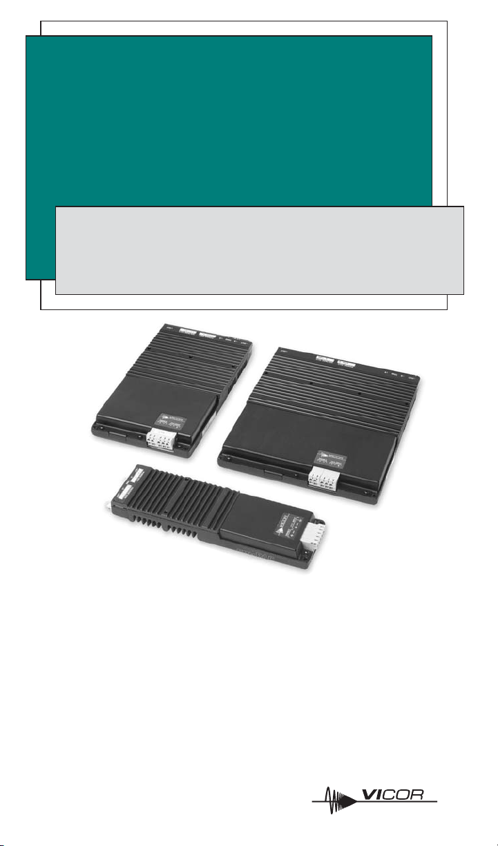
Product Description
The ComPAC family of user-definable power supplies provides a complete
power solution optimized to meet the voltage, noise, and transient
protection input requirements of commercial, industrial, military, and
telecommunications applications. These switchers are available with one,
two, or three outputs and total output ratings up to 600 Watts. Each unit
incorporates one, two, or three component-level Vicor DC-DC converters in
a chassis-mount housing. ComPAC’s unique modular design accommodates
thousands of different configurations.
Page 2
2
20 mA Max.
Disable
DIS+
DIS–
+
V
0.1 1 10ms 100 1000
100V
Normal Operating Area
I.S.W.
Full Load
100V
Standard Wide Range
24V Inputs
0.1 1 10ms 100 1000
800V
Normal Operating Area
I.S.W.
Full Load
300V Input
S.D.
160V
0.1 1 10ms 100 1000
Normal Operating Area
I.S.W.
Full Load
48V Input
R.E.
276V
Normal Operating Area
I.S.W.
Full Load
0.1 1 10ms 100 1000
48V Wide Range Input
R.E.
S.D.
R.E.
R.E.
32V
21V
36V
18V
S.D.
76V
125V
60V
100V
42V
500V
400V
200V
36V
S.D.
S.D.
100V
500ms
500ms
Application Notes
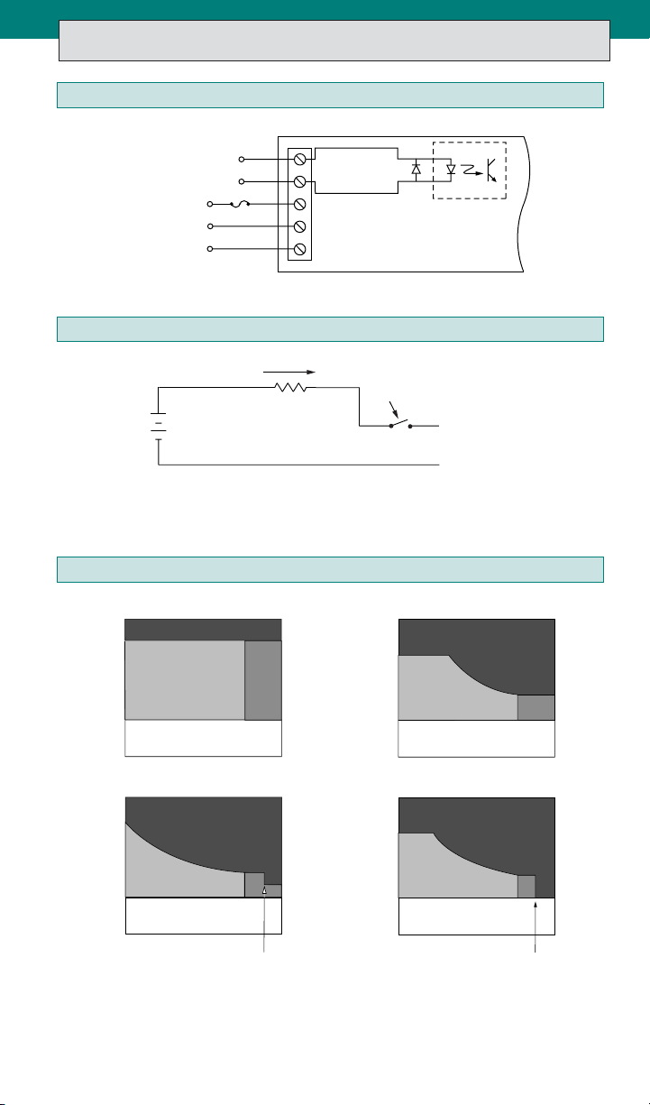
Input Connections
Master Disable
DC Input
Earth Ground
Disable +
Disable –
VIN +
VIN –
GND
See fuse chart on page 6
Master Disable Drive Circuit
The Master Disable input is optically isolated and incorporates a reverse polarity
protection diode. Apply a current of up to 20 mA to disable output(s). See ComPAC
data sheet for minimum levels.
Input Operating Voltage
Long Term Safe Operating Curves. I.S.W. = Input Surge Withstand (no
disruption of performance, 1% duty cycle max.).
R.E. = Ratings Exceeded. S.D. = Shutdown. For short duration transient
capability, refer to product specifications.
Page 3
Thermal Impedance
Note: Not applicable for conduction cooled (–CC) models.
Below are the chassis-to-air thermal impedance values, as a function of airflow,
for ComPAC package configurations that incorporate one, two, and three internal
component DC-DC converters.
Thermal Impedance—Case-to-Air (°C/Watt)
Standard Units With Optional H1 Heatsink
1-Up 2-Up 3-Up 1-Up 2-Up 3-Up
Free Air (Horiz.) 3.6 1.7 1.4 2.1 1.3 1.0
Forced Convection Through Heat sink Fins
50 LFM 2.7 1.4 1.3 1.5 1.1 0.9
100 LFM 2.3 1.3 1.1 1.2 0.9 0.7
250 LFM 1.6 1.0 0.8 0.7 0.5 0.4
500 LFM 1.2 0.7 0.6 0.4 0.3 0.3
750 LFM 0.9 0.5 0.5 0.3 0.2 0.2
1000 LFM 0.8 0.5 0.4 0.2 0.2 0.2
To calculate case temperature: total power dissipated times
thermal impedance plus ambient temperature.
To calculate Watts dissipated per output: output power
divided by efficiency minus output power.
3
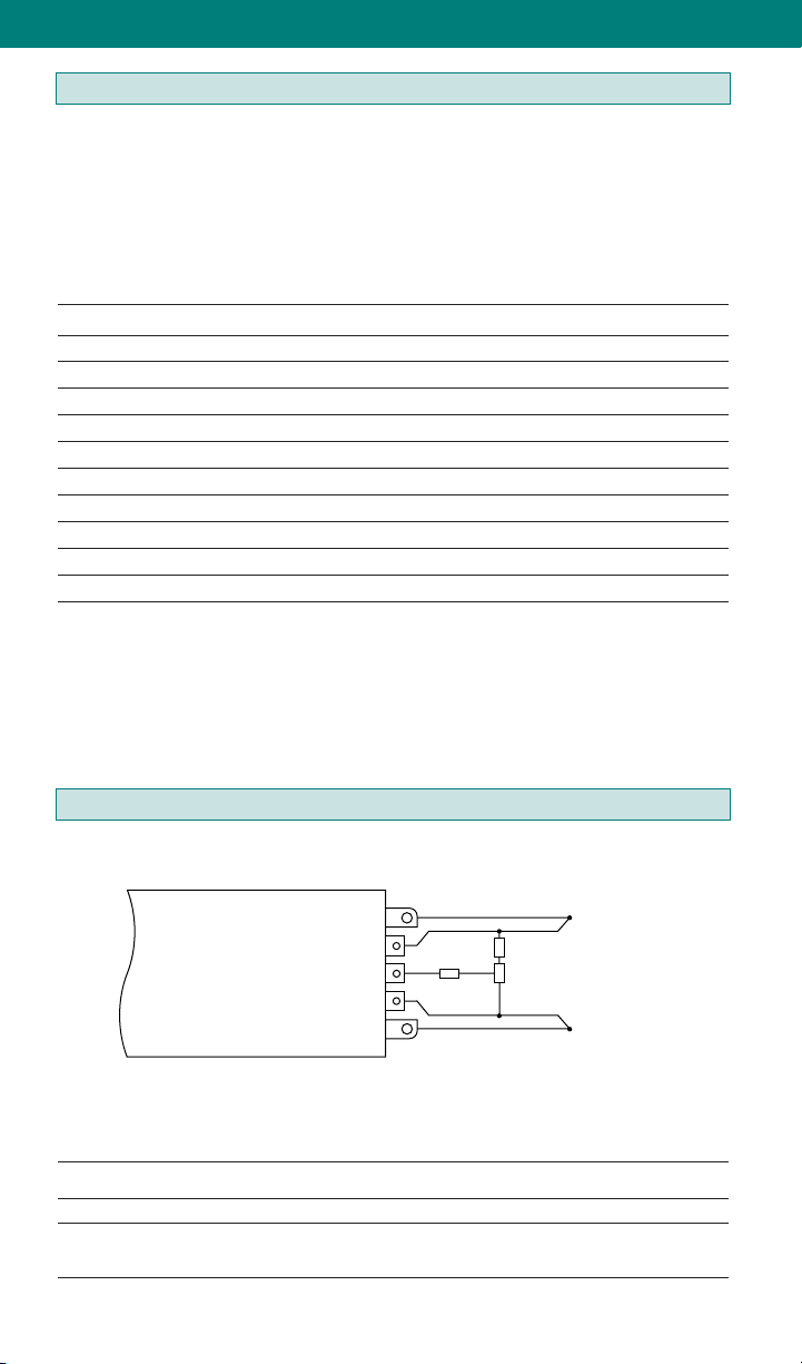
Output Trimming
Trim resistors not required for operation at rated output voltage.
+ OUT
+ SENSE
TRIM
— SENSE
— OUT
R2
+Sense and –Sense must be connected locally or remotely (shown).
Resistor Values for Trimming Standard Output Voltages
Nominal Output Voltage 5 V 12 V 15 V 24 V 28 V 48 V Trim Range
R1(KΩ) .953 15.8 22.1 41.2 48.7 90.9
R2(KΩ) 909090909090
Refer to Applications Manual, Chapter 5, for other trimming methods.
+ V
R1
To Load
10K
— V
+10%, -10%
OUT
OUT
Page 4

4
4.96
(126,0)
4.42
(112,3)
7.380
(187,45)
0.18
(4,6)
6.00
(152,4)
7.00
(177,8)
2.288
(58,12)
2.420
(61,47)
0.20
(5,1)
0.19
(4,8)
5
1
3
2
4
ø.150 ± .005 THRU 6 PLAC
(ø3,81 ± 0,13)
3.58
(90,9)
3.04
(77,2)
4.96
(126,0)
4.562
(115,87)
0.18
(4,6)
6.00
(152,4)
2.281
(57,94)
0.20
(5,1)
0.19
(4,8)
5
1
3
2
4
ø.150 ± .005 THRU 5 PLACES
(ø3,81 ± 0,13)
2.156
(54,76)
0.18
(4,6)
6.00
(152,4)
0.91
(23,1)
2.54
(64,5)
0.20
(5,1)
0.19
(4,8)
0.20
(5,1)
5
1
3
2
4
ø.150 ± .005 THRU 4 PLACES
(ø3,81 ± 0,13)
1.37
(34,80)
0.99
(25,15)
0.5
(12,57)
9.25 ±.120
(235,0 ±3,05)
8.63 ±.025
(219,2
±,64)
0.5
(12,57)
Functional and Mechanical Layout
LC-Series
Single output
50-200 Watts
MC-Series
Single output
100-400 Watts
NC-Series
Single output
300-600 Watts
PC-Series
Dual output
100-400 Watts
QC-Series
Dual output
150-600 Watts
RC-Series
Triple output
150-600 Watts
Inputs
All Models
LC-Series
MC-, PC-Series
NC-, QC-, and RC-Series
Drawing: P.N. 11926
Page 5

5
2.76
(70,1)
OUTPUT 1 OUTPUT 2
OUTPUT 1
OUTPUT 1 OUTPUT 2 OUTPUT 3
#10-32 STUD
2 PLACES
B
D
C
E
A
#8-32 STUD
6 PLACES
A
E
C
B
D
0
5.59 (141,99)
5.25 (133,35)
5.98 (151,89)
6.37 (161,80)
6.95 (176,53)
.25 TYP
A
E
C
B
D
.75 (19,05)
.41 (10,41)
1.14 (28,96)
1.53 (38,86)
2.11 (53,59)
#10-32 STUD
2 PLACES
A
B
D
C
E
A
B
D
C
E
#8-32 STUD
2 PLACES
A
E
C
B
D
3.17 (80,52)
2.83 (53,59)
3.56 (90,42)
3.95 (100.33)
4.53 (115,06)
2.76
(70,1)
OUTPUT 1 OUTPUT 2
OUTPUT 1
#8-32 STUD
4 PLACES
A
E
C
B
D
0
3.17 (80,52)
2.83 (71,88)
3.56 (90,42)
3.95 (100,33)
4.53 (115,06)
.25 TYP
#10-32 STUD
2 PLACES
A
E
C
B
D
.75 (19,05)
.41 (10,41)
1.14 (28,96)
1.53 (38,86)
2.11 (53,59)
B
D
C
E
A
2.76
(70,1)
OUTPUT 1
#8-32 STUD
2 PLACES
A
E
C
B
D
0
.75 (19,05)
.41 (10,41)
1.14 (28,96)
1.53 (38,86)
2.11 (53,59)
.25 TYP
OPTIONAL HEATSINK (H1)
STANDARD UNITS
1.12
(28,4)
0.41
(10,4)
Measure case temperature on this surface.
Outputs
LC-Series
MC-Series PC-Series
Inputs
1 Ground
2–V
IN
3+V
IN
4 –Disable
5 +Disable
Outputs
A +Out
B +Sense
C Trim
D –Sense
E –Out
Consult factory for outline
drawings of models with
conduction cooled (–CC) option.
NC-Series QC-Series RC-Series
Page 6

6
Installation and Operation Guidelines
Input Line Fusing. The ComPAC must be fused externally. The table below lists the fuse
ratings for one-, two-, and three-up units (max. output 200, 400, and 600 Watts).
VI Series
200 W 400 W 600 W
24 V Input 10 A/32 V (AGC-10) 20 A/32 V (AGC-20) 35 A/32 V (AGC-35)
24 V Wide Input 12 A/32 V (3AB-12) 20 A/32 V (AGC-20) 35 A/32 V (AGC-35)
48 V Input 8 A/60 V (3AB-8) 15 A/60 V (3AB-15) 25 A/60 V (3AB-25)
48 V Wide Input 6 A/100 V (3AB-6) 15 A/100 V (3AB-15) 25 A/100 V (3AB-25)
300 V Input 2 A/250 V (3AB-2) 4 A/250 V (3AB-4) 6 A/250 V (3AB-6)
MI Series
Use MIL-F-15160 or MIL-F-23419 equivalents of the commercial fuses listed below.
200 W 400 W 600 W
28 V Input 10 A/250 V (3AB-10) 20 A/250 V (3AB-20) 30 A/125 V (3AB-30)
270 V Input 2 A/250 V (3AB-2) 4 A/250 V (3AB-4) 6 A/250 V (3AB-6)
Grounding
the terminal marked (GND). Use the same wire gauge as that specified for your ComPAC
unit’s input voltage connections, below.
Input Voltage Connections. Connect the line voltage to VIN+ (positive) and VIN– (negative).
For one-up ComPAC models (max. output 200 W), use #16 input wire; for two-up and three-
up models (max. output 400 W and 600 W), use #14 input wire. Be sure to tighten the lead
connections securely—recommended connector screw torque is 3.5 in-lbs (0.4 N-m).
Recommended strip length is 9 mm.
Output Wire Gauge. Use the output wire gauge that corresponds to the output current of
your ComPAC unit, below:
105 A–160 A : #4 26 A–40 A : #10 7 A–10 A : #16
66 A–104 A : #6 16 A–25 A : #12 4 A–6 A : #18
41 A–65 A : #8 11 A–15 A : #14 0 A–3 A : #20
. For safe operation, the ComPAC unit must be grounded. Connect a ground lead to
Output Voltage Trimming. Do not trim the outputs higher than 110% of their nominal
output voltage. When an output is trimmed up, do not exceed its maximum rated output power.
Operating Temperature. Do not allow the ComPAC to exceed its maximum operating
temperature, which is reached when the heat sink/–CC plate is 85°C. (Full power can be
delivered up to this temperature.) Heat sink temperature is a function of the output power
and voltage of the supply, ambient temperature, and airflow across the heat sink. Refer to the
Vicor Applications Manual to determine the maximum ambient temperature for your
application. Always use worst-case conditions when calculating operating temperature.
Note: To ensure proper heat transfer from the internal module(s) to the heat sink, the
mounting holes through the heat sink (2, 3, and 4 holes on one-, two-, and three-up models,
respectively) must contain properly torqued screws at all times during operation, whether or
not the unit is mounted.
Page 7

EXTERNAL TOOTH
LOCKWASHER
#10 TERMINAL
RETAINING NUT
#10 NUT PLATE
USER OUTPUT
TERMINALS
#10 BRASS STUD
HELICAL
LOCKWASHER
(FITS WITHIN
OPENING PROVIDED)
TERMINAL COVER
NEGATIVE
If the unit is operated unmounted, insert a #6 or metric flathead screw
through each hole from below and secure with a nut on top, torqued to 6 in-
lbs (0.7 N-m). A thermal interface material is recommended for –CC models
– consult factory.
Output Terminal Connections. A hardware kit with parts for output terminal
connections is provided with each ComPAC unit. The following drawing
shows the assembly of those parts for the proper connection of metal power
terminals. Assembly for PCB power terminals is the same except that they do
not require an external tooth lockwasher. Consult the table below for the
recommended torque level for each stud size.
Metal Terminal
7
For More Information
The Vicor Applications Manual and product data sheet contain complete
information about ComPAC DC-DC Switchers. To receive literature or to
consult an applications engineer about installation or operation of this product,
contact your nearest Vicor office. (See page 8.)
“AMP” and “Faston” are registered trademarks of AMP, Incorporated, Harrisburg, PA.
Drawing: P.N. 10894 #1
Terminal and Terminal Recommended
Product Model Style Stud Size Torque
–Output, +Output
LC-, PC-, & PCB 8-32 UNC 10 in-lbs (1.1 N-m)
RC-Series
MC- & NC-Series Metal 10-32 UNC 15 in-lbs (1.7 N-m)
QC-Series PCB 8-32 UNC 10 in-lbs (1.1 N-m)
Metal 10-32 UNC 15 in-lbs (1.7 N-m)
Supervisory Sized to accept AMP Faston®insulated
All models receptacle #2-520184-2
(Bitte lesen Sie die Sicherheits-Vorschriften auf Seite 8.)
Page 8

8
Sicherheits-Vorschriften
Absicherung am Eingang. Das ComPAC muß mit einer externen
Sicherung am Eingang versehen werden. Die entsprechenden
Sicherungswerte entnehmen Sie bitte der Tabelle auf Seite 6 unter der
Rubrik “Input Line Fusing”.
Erdung. Um den IEC 950 Klasse I Erdungsforderungen zu
entsprechen, muß ein Erdungskabel an den Anschluß (GND)
angeschlossen werden. Für ComPAC Modelle mit einem Modul (max.
Leistung 200 W) benutzen Sie bitte AWG 16- und für Modelle mit 2
und 3 Modulen (max. Leistung 400 W und 600 W) AWG 14-Kabel.
Anschlüsse Eingangsspannung. Vergewissern Sie sich, daß die Kabel
für die Eingangsspannung fest angeschlossen sind und achten Sie auf
die Polarität.
Betriebstemperatur. Die maximale Betriebstemperatur des ComPAC-
Gerätes darf nicht überschritten werden. Dies ist gegeben, wenn der
Kühlkörper eine Temperatur von 85 Grad Celsius erreicht hat.
Weitere Informationen. Das Vicor Applications Manual und
Produkt-Datenblätter enthalten ausführliche Informationen über
ComPAC DC-DC Wandler. Fordern Sie bitte Unterlagen bei Vicor
oder Ihrer nächsten Vicor Vertretung an.
Visit the Vicor website at:
www.vicorpower.com
Vicor Corporation
Andover, MA, U.S.A
Tel: 800-735-6200
Fax: 978-475-6715
Vicor France
Tel: +33-1-3452-1830
Fax: +33-1-3452-2830
Vicor Germany
Tel: +49-89-962-439-0
Fax: +49-89-962-439-39
Printed in U.S.A. Pt. No. 23935 Rev 4.1 11/09
Chicago, IL
Tel: 630-769-8780
Fax: 630-769-8782
Vicor Italy
Tel: +39-2-2247-2326
Fax: +39-2-2247-3166
Vicor U.K.
Tel: +44-1276-678-222
Fax: +44-1276-681-269
Sunnyvale, CA
Tel: 408-522-5280
Fax: 408-774-5555
Vicor Hong Kong
Tel: +852-2956-1782
Fax: +852-2956-0782
Vicor Japan
Tel: +81-3-5487-3880
Fax: +81-3-5487-3885
 Loading...