

Page 1
FlatPAC Family
50 to 600 Watt
AC-DC Switchers
Application Notes
Functional and Mechanical Layout
Installation and Operation Guidelines
Product Description
The FlatPAC family of user-definable offline power supplies provides a complete
power solution that incorporates one, two, or three standard Vicor DC-DC converters
and a front-end subassembly in a modular package. FlatPAC is available with one,
two, or three outputs and total output ratings of up to 600 W. The two-up and
three-up models (maximum output 400 W and 600 W) feature an autoranging input,
which automatically senses the input line voltage and sets the power supply’s input
range accordingly. FlatPAC’s unique modular design accommodates over 10,000
different configurations.
FlatPAC switchers that contain BatMod current source modules instead of VI-200
converters are indicated by the suffix -BM following the FlatPAC part number.
BatMod converters provide a programmable output current, rather than a controlled
output voltage. Consequently, the output supervisory terminal functions differ on
FlatPACs with BatMod modules.
F-Series
(Strappable Input)
A-Series
(Autoranging Input)
12
Page 2
Application Notes
2
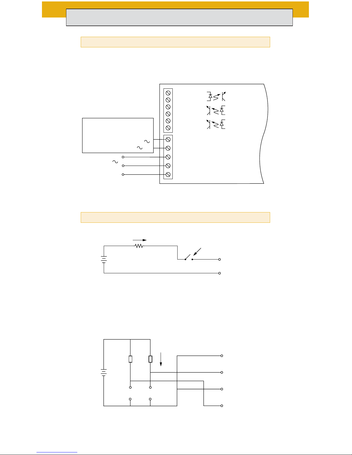
MOD-DIS Input. Apply a current of 1–30 mA to disable output.
Forward voltage drop of internal opto diode is 1.65 V max. @
30 mA max.
AC-OK and BUS-OK Status Outputs. Output transistors saturated
if OK. Vce sat. = < 0.4 V @ 1.5 mA. Maximum voltage is 70 Vdc.
30 mA max.
Disable
MOD DIS +
MOD DIS –
V
+
AC OK –
AC OK +
BUS OK –
Status
1.5mA max.
V
+
r
r
AC Mains Connections
Supervisory Connections (2-up and 3-up models)
AC Mains
Earth Ground
MOD DIS –
MOD DIS +
AC OK –
AC OK +
BUS OK –
BUS OK +
Internal
Supervisory
Circuits
(Optocouplers)
Autoranging models:
Do not connect
Manual strap models:
Connect for 115 Vac
Open for 230 Vac
ST2
ST1
L2/N
L1
GND
Page 3
3
+Sense and –Sense must be connected locally or remotely (shown).
+ V
OUT
To Load
– V
OUT
R1
10K
R2
+ OUT
+ SENSE
TRIM
– SENSE
– OUT
RESISTOR VALUES FOR TRIMMING STANDARD OUTPUT VOLTAGES
Nominal Output Voltage 5 V 12 V 15 V 24 V 28 V 48 V Trim Range
R1(kΩ) .953 15.8 22.1 41.2 48.7 90.9
R2(kΩ)909090909090
+10%, -10%
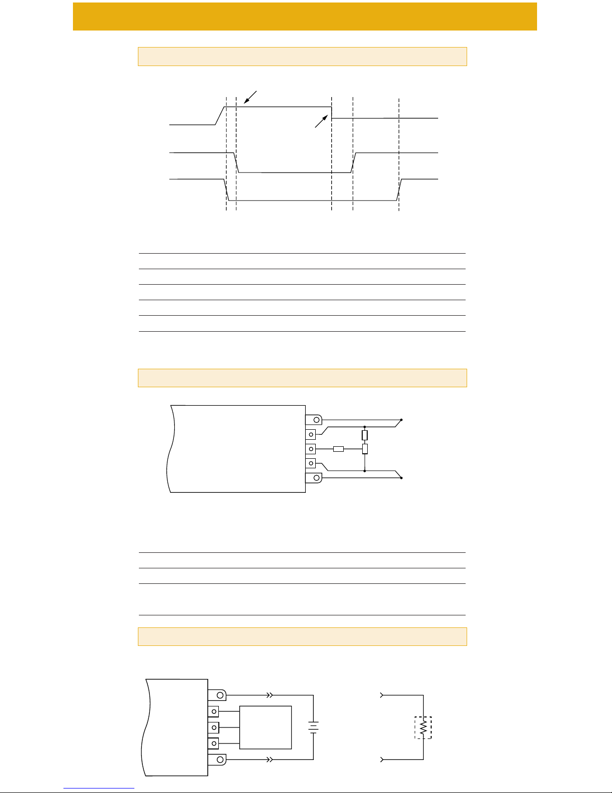
V
LINE
> 90 (180) Vac
AC Line
Interrupted
AC
Line
AC OK
DC OK
T0
T1 T2
T3
T4
Conditions: Full Load 90 (180) Vac, AC Line
Timing Diagram—Status Signals (2-up and 3-up models)
Output Trimming (All models with VI-200s)
Battery
Charger
External
Control
Functions
+ OUT
V
TRIM
I
TRIM
I
MON
– OUT
Programmable
Current Source
12–48V
Battery
+
–
➧
➧
Load
+
–
OR
Typical Applications (FlatPACs with BatMods only)
Time Interval Min Typ Max Units Notes
T1-T0 0 0.1 1.0 ms
T3-T2 0 – – ms
T4-T2 5 – – ms Ride-through time
T4-T3 5 – – ms AC fail warning time
Page 4

Functional and Mechanical Layout
4
LF-Series
Single output
50-200 W
MA/MF-Series
Single output
200-400 W
NA/NF-Series
Single output
450-600 W
PA/PF-Series
Dual output
100-400 W
QA/QF-Series
Dual output
250-600 W
RA/RF-Series
Triple output
150-600 W
NA-, QA-, and RA-Series
MA-, PA-Series
LF-Series
Inputs
All Models
10
11
8
9
7
6
1
2
5
4
3
7.38
(187,5)
1.99
(50,6)
4.42
(106,7)
.20
(5,1)
.18
(4,6)
6.00
(152,4
2.288
(58,12)
2.420
(61,47)
7.00
(177,8)
.20
(5,1)
5 PLACES
.25
(6,4)
5 PLACES
.19
(4,8)
12
ø.150 ± .005
(ø3,81 ± 0,13)
THRU 6 PLACES
.18
(4,6)
6.00
(152,4)
.192
(4,88)
2.156
(54,77)
2.54
(64,5)
.20
(5,1)
.87
(22,1)
.20
(5,1)
TYP
1
3
5
4
2
12
ø.150 ± .005
(ø3,81 ± 0,13)
THRU 4 PLACES
.199
(5,06)
.90
(22,9)
3.05
(77,5)
4.96
(126,0)
.25
(6,4)
.20
(5,1)
.20
(5,1)
.18
(4,6)
2.281
(57,94)
9
7
11
8
6
1
2
5
4
3
10
5 PLACES
5 PLACES
4.562
(115,87)
6.0
(152
ø.150 ± .005
(ø3,81 ± 0,13)
THRU 5 PLAC
1.37
(34,8)
Page 5

5
Drawing: P.N. 10873
NA-Series QA-Series RA-Series
MA-Series PA-Series
LF-Series
Outputs
Inputs
1 Earthground
2L1
3 L2/N
4
1
ST1
51ST2
6 BUS OK+
7 BUS OK–
8 AC OK+
9 AC OK–
10 MOD DIS+
11 MOD DIS–
1
Not used on
autoranging models
Outputs
A +Out
B +Sense*
C Trim*
D –Sense*
E –Out
*
On FlatPACs
with BatMods:
BV
TRIM
CI
TRIM
DI
MON
#8-32 STUD
#10-32 STUD
#10-32 STUD
#8-32 STUD
6 PLACES
2.76
(70,1)
3.07
(78,0)
E
D
C
B
A
E
D
C
B
A
E
D
C
B
A
E
D
C
B
A
E
D
C
B
A
E
D
C
B
A
.41 (10,41)
6.95 (176,53)
6.37 (161,80)
5.98 (151,89)
5.59 (141,99)
5.25 (133,35)
4.53 (115,06)
3.95 (100,33)
3.56 (90,42)
3.17 (80,52)
2.83 (71,88)
2.11 (53,59)
1.53 (38,86)
1.14 (28,96)
.75 (19,05)
0
.25 TYP
OUTPUT 1
OUTPUT 2
OUTPUT 3
OUTPUT 1
OUTPUT 2
OUTPUT 1
2.76
(70,1)
#8-32 STUD
2 PLACES
E
D
C
B
A
.41 (10,41)
2.11 (53,59)
1.53 (38,86)
1.14 (28,96)
.75 (19,05)
0
.25 TYP
OUTPUT 1
2.76
(70,1)
3.07
(78,0)
12
#10-32 STUD
2 PLACES
E
D
C
B
A
#8-32 STUD
4 PLACES
E
D
C
B
A
E
D
C
B
A
.41 (10,41)
4.53 (115,06)
3.95 (100,33)
3.56 (90,42)
3.17 (80,52)
2.83 (71,88)
2.11 (53,59)
1.53 (38,86)
1.14 (28,96)
.75 (19,05)
0
.25 TYP
OUTPUT 1
OUTPUT 2
OUTPUT 1
ES
0.41
(10,4)
1.12
(28,5)
9.25
(235,0)
8.61
(218,7)
Page 6

Fusing. The FlatPAC’s internal fuses are not user-replaceable. Please return the
unit to vendor if servicing is necessary.
Grounding. For safe operation, the FlatPAC unit must be grounded. Connect a
ground lead to the terminal marked (GND). Use the same wire gauge as that
specified for your FlatPAC unit’s input voltage connections, below.
Input Voltage Connections. Connect the line voltage to L1 (hot) and L2N
(neutral). For one-up FlatPAC models (max. output 200 W), use #16 input wire; for
two-up and three-up models (max. output 400 W and 600 W), use #14 input wire.
Recommended connector screw torque is 5 to 7 in-lbs (0.5 to 0.8 N-m). Use your
FlatPAC model only with the corresponding input voltages and frequencies shown
in the table below. Either connect or do not connect ST1 to ST2 as indicated.
Output Wire Gauge. Use the output wire gauge that corresponds to the output
current of your FlatPAC unit, below:
105 A–160 A : #4 26 A–40 A : #10 7 A–10 A : #16
66 A–104 A : #6 16 A–25 A : #12 4 A–6 A : #18
41 A–65 A : #8 11 A–15 A : #14 0 A–3 A : #20
Output Voltage Trimming. Do not trim the outputs higher than 110% of their
nominal output voltage. When an output is trimmed up, do not exceed its
maximum rated output power.
Operating Temperature. Do not allow the FlatPAC to exceed its maximum
operating temperature, which is reached when the heat sink is 85°C. (Full power
can be delivered up to this temperature.) Heat sink temperature is a function of the
output power and voltage of the supply, ambient temperature, and airflow across
the heat sink. Refer to the Vicor Applications Manual to determine the maximum
ambient temperature for your application. Always use worst-case conditions when
calculating operating temperature. Note: To ensure proper heat transfer from the
internal module(s) to the heat sink, the mounting holes through the heat sink (2, 3,
and 4 holes on one-, two-, and three-up models, respectively) must contain
torqued screws at all times during operation, whether or not the unit is mounted.
Installation and Operation Guidelines
6
90–132 Vac 180–264 Vac
C-Grade
Model 47–63 Hz
Strappable VI– ■■ F–C■■ Connect Open
Autoranging VI–■■ A–C ■■ Open Open
90–132 Vac 180–264 Vac
I-Grade
Model 47–440 Hz
Strappable VI– ■■ F–I ■■ Connect Open
Autoranging VI–■■ A–I ■■ Open Open
Page 7

If the unit is operated unmounted, insert a #6 or metric screw through each hole
from below and secure with a nut on top, torqued to 6 in-lbs (0.7 N-m).
Output Terminal Connections. A hardware kit with parts for output terminal
connections is provided with each FlatPAC unit. The following drawing shows the
assembly of those parts for the proper connection of metal power terminals.
Assembly for PCB power terminals is the same except that they do not require an
external tooth lockwasher. Consult the table below for the recommended torque
level for each stud size.
For More Information
The Vicor Applications Manual and product data sheet contain complete
information about FlatPAC AC-DC Switchers. To receive literature or to consult
an applications engineer about installation or operation of this product, contact
your nearest Vicor office. (See page 8.)
(Bitte lesen Sie die Sicherheits-Vorschriften auf Seite 8.)
“AMP” and “Faston” are registered trademarks of AMP, Incorporated, Harrisburg, PA.
7
Metal Terminal
Drawing: P.N. 10894 #1
Terminal and Terminal Recommended
Product Model Style Stud Size Torque
–Output, +Output
LF-, PA/PF-, & PCB 8-32 UNC 10 in-lbs (1.1 N-m)
RA/RF-Series
MA/MF- & Metal 10-32 UNC 15 in-lbs (1.7 N-m)
NA/NF-Series
QA/QF-Series PCB 8-32 UNC 10 in-lbs (1.1 N-m)
Metal 10-32 UNC 15 in-lbs (1.7 N-m)
Supervisory Sized to accept AMP Faston®insulated
All models receptacle #2-520184-2
EXTERNAL TOOTH
LOCKWASHER
#10 TERMINAL
RETAINING NUT
#10 NUT PLATE
USER OUTPUT
TERMINALS
#10 BRASS STUD
HELICAL
LOCKWASHER
(FITS WITHIN
OPENING PROVIDED)
TERMINAL COVER
NEGATIVE
Page 8

Sicherheits-Vorschriften
8
Sicherungen. Die internen Sicherungen im FlatPAC können nicht vom Anwender
ausgetauscht werden. Für Servicearbeiten schicken Sie das Teil bitte an den
Händler zurück.
Erdung. Um den IEC 950 Klasse I Erdungsforderungen zu entsprechen, muß ein
Erdungskabel an den Anschluß (GND) angeschlossen werden. Für FlatPAC
Modelle mit einem Modul (max. Leistung 200W) benutzen Sie bitte AWG 16- und
für Modelle mit 2 und 3 Modulen (max. Leistung 400 W und 600 W) AWG 14-Kabel.
Eingangsverbindungen. Abhängig von Ihrem FlatPAC Modell und der
Eingangsspannung müssen ST1 und ST2 offen sein oder miteinander verbunden
werden—wie nachstehend aufgeführt.
Modell 90-132 Vac 180-264 Vac
Strappable (VI–■■ F–■■ ■■ ) Verbinden Offen
Autoranging (VI–■■ A–■■ ■■ ) Offen Offen
Betriebstemperatur. Die maximale Betriebstemperatur des FlatPAC-Gerätes darf
nicht überschritten werden. Dies ist gegeben, wenn der Kühlkörper eine
Temperatur von 85 Grad Celsius erreicht hat.
Weitere Informationen. Das Vicor Applications Manual und Produkt-Datenblätter
enthalten ausführliche Informationen über FlatPAC AC-DC Wandler. Fordern Sie
bitte Unterlagen bei Vicor oder Ihrer nächsten Vicor Vertretung an.
Vicor Corporation
Andover, MA, U.S.A
Tel: 978-470-2900
Fax: 978-475-6715
Vicor France
Tel: +33 1 34 52 18 30
Fax: +33 1 34 52 28 30
Vicor Germany
Tel: +49 89 962 439 0
Fax: +49 89 962 439 39
Chicago, IL
Tel: 630-769-8780
Fax: 630-769-8782
Vicor Italy
Tel: +39 02 22 47 23 26
Fax: +39 02 22 47 31 66
Vicor U.K.
Tel: +44 1276 678222
Fax: +44 1276 681269
Sunnyvale, CA
Tel: 408-522-5280
Fax: 408-774-5555
Vicor Hong Kong
Tel: +852-2956-1782
Fax: +852-2956-0782
Vicor Japan
Tel: +81-3-5487-3880
Fax: +81-3-5487-3885
Printed in U.S.A. Pt. No. 23786 Rev 4.0 2/04/100M
Visit Vicor’s Website at:
vicorpower.com
 Loading...