

Page 1
VZ7656E1000W
Zigbee™ Wireless RTU Terminal Equipment
Controller with IAQ Control
Installation Guide
For Commercial Zoning Systems
January 10th, 2012 / 028-0327-R1
CONTENTS
Installation 2
Location 2
Installation 2
Theory of Operation 3
Features overview 3
Wireless System Overview 5
Terminal, Identification and Function 6
Wiring 6
Screw terminal arrangement and wiring 7
Typical Applications 7
Main outputs wiring 7
Remote sensor accessories 8
Configuring and Status Display Instructions 9
Status display 9
User interface 11
User configuring instructions menu 11
Local keypad interface 12
Installer Configuration Parameter Menu 16
Fresh Air Damper Control Sequences 27
Specifications 31
Drawing & Dimensions 32
1 | VZ7656E1000W Installation Guide
Page 2
INSTALLATION
Remove the security screw on the bottom of
Terminal Equipment Controller cover.
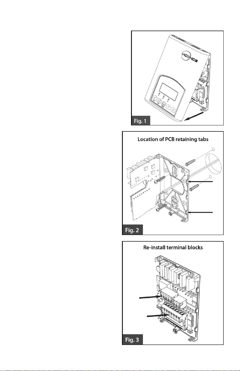
Open unit by pulling on the bottom
side of Terminal Equipment
Controller (fig. 1).
Remove wiring terminals from sticker.
Please read the FCC ID and IC label
installed in the cover upon removal of
cover for the wireless products.
Location
1. Should not be installed on an outside
wall.
2. Must be installed away from any
direct heat source.
3. Should not be installed near an
air discharge grill.
4. Should not be affected by direct
sun radiation.
5. Nothing should restrict vertical
air circulation to the Terminal
Equipment Controller.
Installation
1. Swing open the Terminal
Equipment Controller PCB to
the left by pressing the PCB
locking tabs (fig. 2).
2. Pull out cables 6” out from the
wall.
3. Wall surface must be flat and
clean.
4. Insert cable in the central hole
of the base.
5. Align the base and mark the
location of the two mounting
holes on the wall. Install base in
the proper orientation. Arrow on
base should be facing up.
6. Install anchors in the wall.
7. Insert screws in mounting holes
on each side of the base (fig. 2).
8. Gently swing back the circuit
board on the base and push on
it until the tabs lock it.
9. Strip each wire 1/4 inch from
end.
2 | VZ7656E1000W Installation Guide
Page 3
10. Insert each wire according to wiring diagram.
When replacing an existing Terminal Equipment Controller, label the
wires before removal of the Terminal Equipment Controller.
Electronic controls are static sensitive devices. Discharge yourself
properly before manipulating and installing the Terminal Equipment
Controller.
A short circuit or improper wiring may permanently damage the Terminal
Equipment Controller or the equipment.
All VT7000 series Terminal Equipment Controllers are designed for use
as operating controls only and are not safety devices. These instruments
have undergone rigorous tests and verification prior to shipping to ensure
proper and reliable operation in the field. Whenever a control failure
could lead to personal injury and or loss of property, it becomes the
responsibility of the user or installer or electrical system designer to
incorporate safety devices (such as relays, flow switch, thermal
protections, etc…) and or an alarm system to protect the entire system
against such catastrophic failures. Tampering with the devices or
unintended application of the devices will result in a void of warranty.
11. Gently push excess wiring back into hole (fig. 3).
12. Re-Install wiring terminals in their correct locations (fig. 3).
13. Re-install the cover (top side first) and gently push extra wire length back into
the hole in the wall.
14. Install security screw.
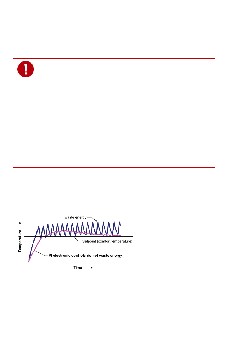
THEORY OF OPERATION
The VZ7656 series uses a Viconics proprietary adaptive logic algorithm to control the
space temperature. This algorithm controls the heating and or air conditioning system to
minimize overshoot while still providing comfort. It provides exceptional accuracy due to
its unique PI time proportioning control algorithm, which virtually eliminates temperature
offset associated with traditional, differential-based On-Off thermostats.
Fig.2 - On-Off mechanical control vs. PI electronic control.
Features overview
7 day schedule models, 2 or 4 events.
Supports up to 120 zones per system WITHOUT any network wires.
C02 control logic based on fresh air volume or fresh air damper position.
Fresh air damper output for building C02 level control.
Gas, oil or electric system compatibility.
3 | VZ7656E1000W Installation Guide
Page 4

Remote outdoor sensing capability for added flexibility.
- System mode heating and cooling lockout.
- Zone perimeter reheat lockout.
Remote discharge air sensor input for monitoring and control purpose.
- System efficiency feedback.
- Discharge high limit heating lockout.
- Discharge low limit cooling lockout.
Remote return air sensor input for monitoring control.
- System efficiency feedback.
- Return high limit heating lockout.
- Return low limit cooling lockout.
- Communication lost control function.
Password protected configuration menu and lockable keypads for security.
A configurable digital input for added flexibility. The input can be configured as the
following:
None: No function will be associated with the input.
Service: a backlit flashing Service alarm will be displayed on the Terminal
Equipment Controller LCD screen when the input is energized. It can be tied in
to the AC unit control card, which provides an alarm in case of malfunction.
Filter: a backlit flashing Filter alarm will be displayed on the Terminal
Equipment Controller LCD screen when the input is energized. It can be tied to a
differential pressure switch that monitors filters.
RemNSB: remote NSB timer clock input. Will disable the internal scheduling of
the Terminal Equipment Controller. The scheduling will now be set as per the
digital input. The menu part related to scheduling is disabled and no longer
accessible. It provides low cost setback operation via occupancy sensor or from
a dry contact.
RemOVR: temporary occupancy contact. Disables all override menu function of
the Terminal Equipment Controller. . The override function is now controlled by a
manual remote momentarily closed contact. When configured in this mode, the
input operates in a toggle mode.
With this function enabled it is now possible to toggle between unoccupied &
occupied setpoints for the amount of time set by parameter (TOccTime)
temporary occupancy time.
Automatic smart fan operation saves energy during unoccupied periods.
Non volatile EEPROM memory prevents loss of parameters during power shortage.
Configurable SPST output relay on scheduling models for lighting, exhaust fan or
fresh air control.
6 hour typical reserve time for clock in case of power loss.
Built in 0 to 10 VDC by-pass damper / VFD output logic for static pressure control.
- Built in static pressure loop control.
- 0 to 5 VDC static pressure input.
Easy configuration and self-binding operation
Easy configuration without using any special software or additional tools.
Can be used as stand-alone or with supervision controller for monitoring purposes.
Truly scalable in terms of supported number of zones and RTU units.
4 | VZ7656E1000W Installation Guide
Page 5
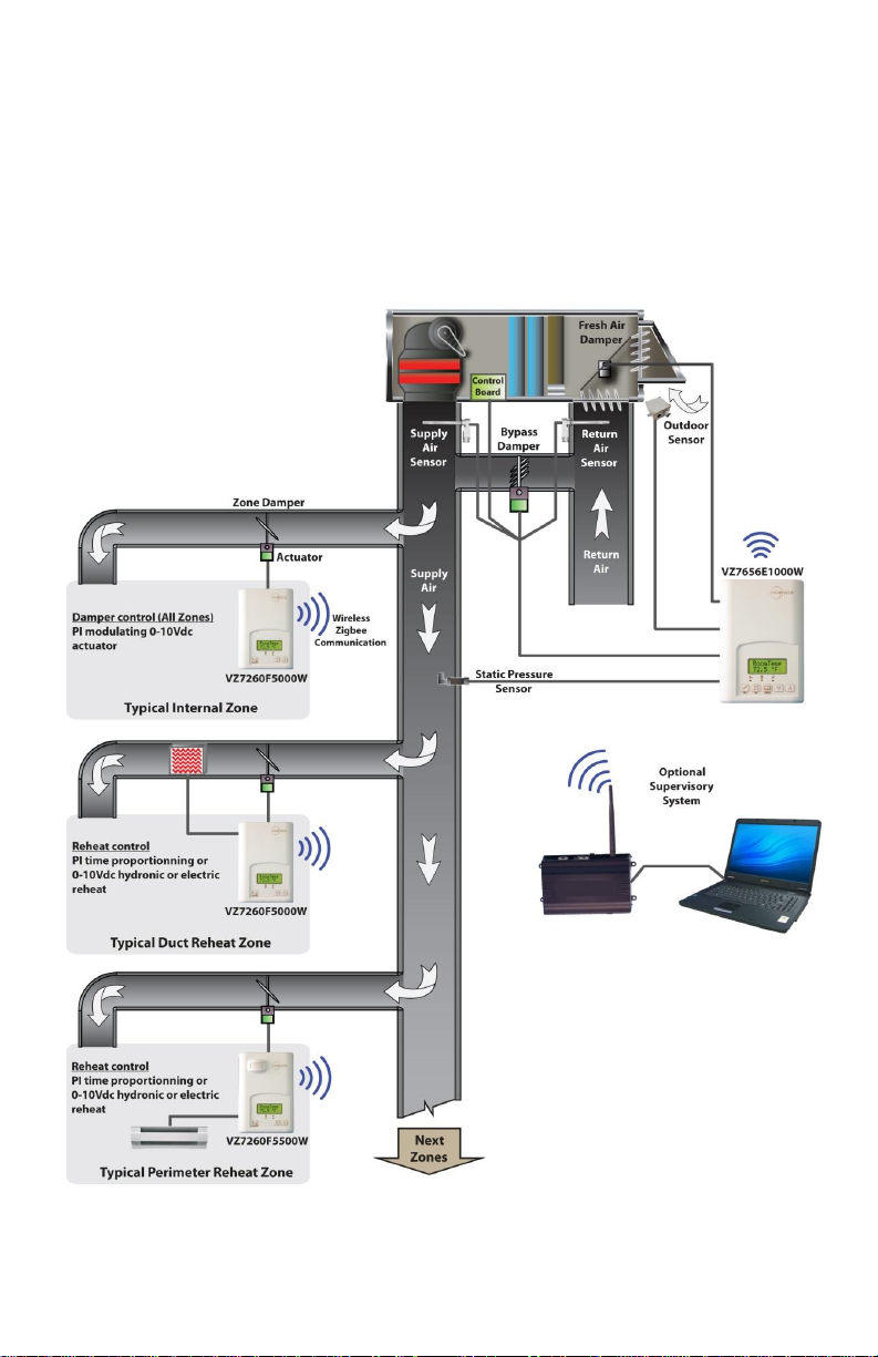
WIRELESS SYSTEM OVERVIEW
Viconics VZ7260X5X00W Zone controllers are used in conjunction with the
VZ7656X1000W roof top controllers. Combined, they are designed for operating typical;
single or multistage RTU’s and their associated local zones. For example, a typical job
layout system may feature 3 RTU controllers and a total of 31 zones. This would bring to
total number of nodes (individual Com addresses) to 34. RTU 1 would have 10 zones
under its command, RTU 2 would have 10 zones under its command and RTU 3 would
have 11 zones under its command.
Typical Wireless Zoning System Installation
5 | VZ7656E1000W Installation Guide
Page 6
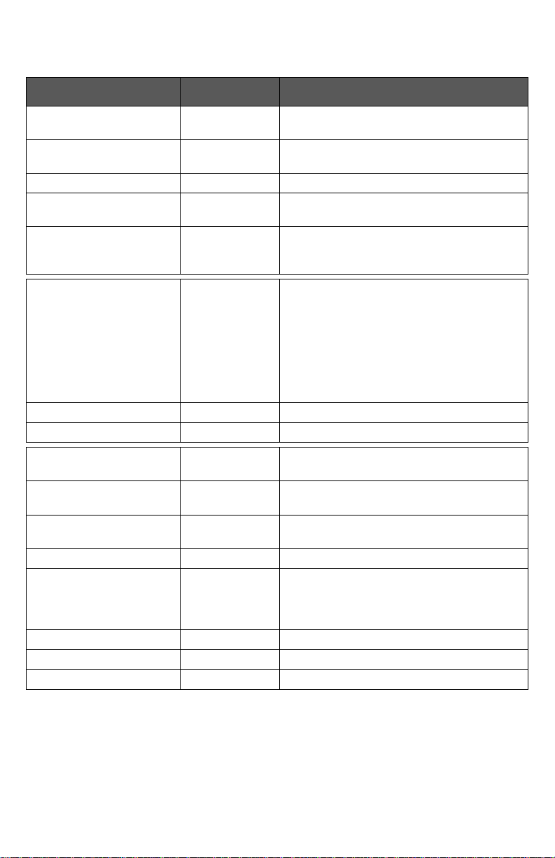
TERMINAL, IDENTIFICATION AND FUNCTION
Terminal Use
Terminal
Identification
Description
1 – Cool 2
Y2
Output for cooling / compressor stage
number 2.
2 – Cool 1
Y1
Output for cooling / compressor stage
number 1.
3 - Fan G Output for the fan.
4 - 24 V ~ Hot
RC
Power supply of controller, hot side
(Delivered from the RTU).
5 - 0 V ~ Com
C
Power supply of controller, common side.
Also used as reference for the analog BPD
output when used (Delivered from the RTU).
6- Heat Switch Leg
RH
24 VAC switched leg for the heating stages.
If heating stages are part or RTU,
install a jumper across RC & RH.
If heating stages are part of separate
equipment with a different power
supply, feed external switched power
leg through RH without installing a
jumper across RC & RH.
7 – Heat 1
W1
Output for heating stage number 1.
8- Heat 2
W2
Output for heating stage number 2.
9 – By-pass damper
BPD
Local analog 0 - 10 VDC by-pass damper /
VFD output.
10 – Economizer Output
EC
0-10 VDC analog fresh air damper /
economizer output.
11 – Static pressure
SP
Local analog 0 – 5 VDC static pressure
input.
12 – AI
AI
0-10 VDC analog input for airflow transmitter
13 - RS
RS
Return air temperature sensor input. If
sensor fails, controller will use the on-board
thermistor sensor to control if the
communication is lost.
14 - Scom
Scom
Reference input for DI 1, RS, OS & DS.
15 - OS
OS
Outside air temperature sensor input.
16 - DS
DS
Discharge air temperature sensor input.
Wiring
6 | VZ7656E1000W Installation Guide
Page 7
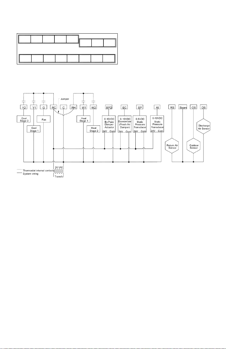
Screw terminal arrangement and wiring
BPD
EC
SP
AI
RS
SCom
OS
DS G Y1
Y2
W2
W1
RH C RC
VZ7656E Controller Terminals
TYPICAL APPLICATIONS
Main outputs wiring
Wiring notes:
Note 1: If the same power source is used for the heating stages, install jumper across RC &
RH. Maximum current is 2.0 amps.
Note 2: If auxiliary output is used to toggle occupancy of the electronic control card inside
the equipment, configure the relay parameter (Aux cont) to the N.O. setting. A
second relay can be added for additional functionality of the occupancy output.
Note 3: Analog outputs and inputs use a half bridge rectifier. Reference of the control
signal is the common of the power supply of the Terminal Equipment Controller.
(Terminal C)
Note 4: Electromechanical contacts are to be used with the digital inputs. Electronic triacs
cannot be used as mean of switching for the input. The switched leg to the input for
the input to activate is terminal C (common)
Note 5: The transformer of the unit provides power to the t Terminal Equipment Controller
and the additional loads that will be wired to the Terminal Equipment Controller.
7 | VZ7656E1000W Installation Guide
Page 8
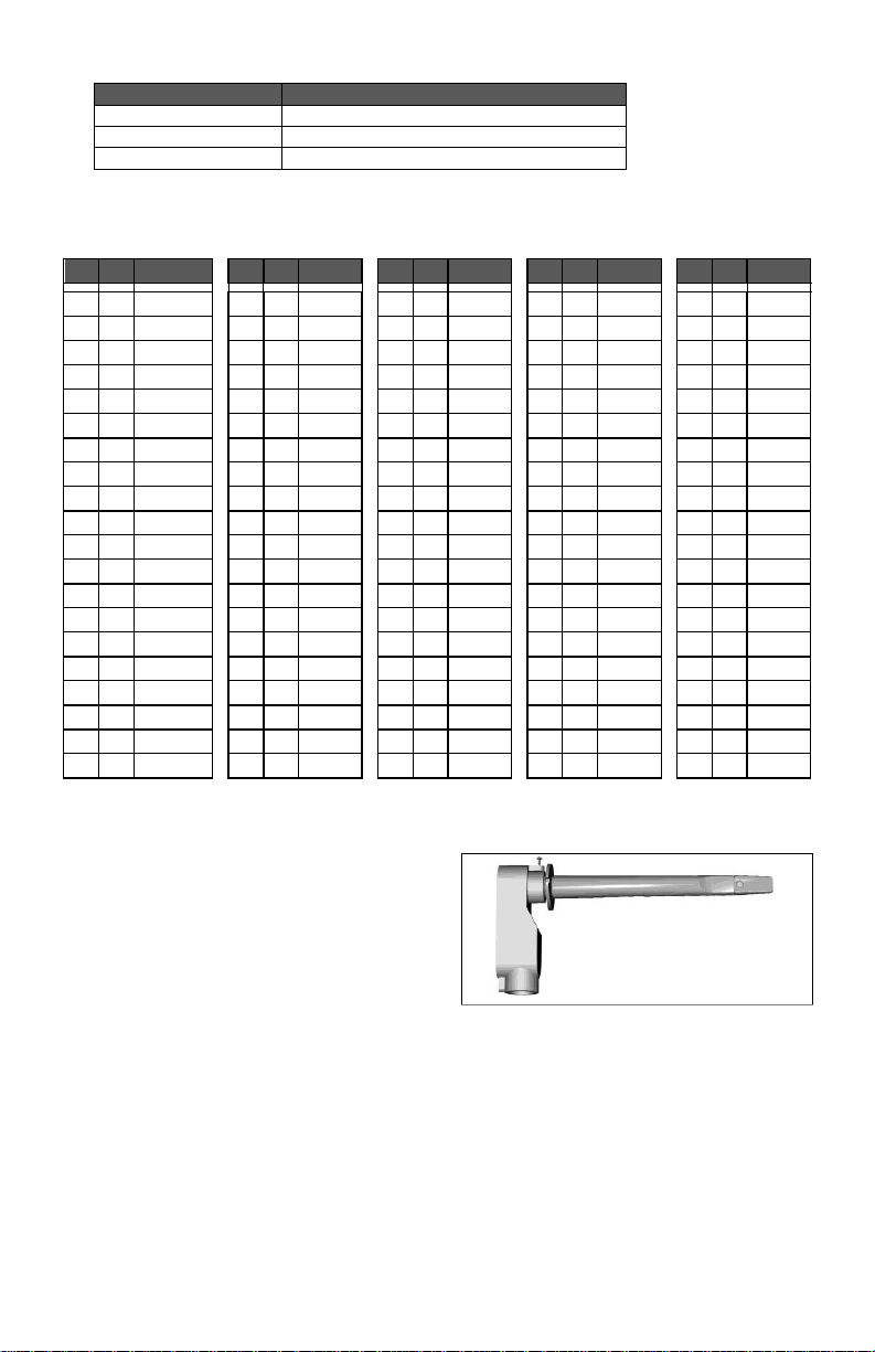
Remote sensor accessories
Model no.
Description
S2020E1000
Outdoor temperature sensor
S2060A1000
Averaging temperature sensor
S2000D1000
Duct mounted temperature sensor
ºC
ºF
Kohm
ºC
ºF
Kohm
ºC
ºF
Kohm
ºC
ºF
Kohm
ºC
ºF
Kohm
-40
-40
324.3197
-20
-4
94.5149
0 32
32.1910
20
68
12.4601
40
104
5.3467
-39
-38
303.6427
-19
-2
89.2521
1 34
30.6120
21
70
11.9177
41
106
5.1373
-38
-36
284.4189
-18 0 84.3147
2 36
29.1197
22
72
11.4018
42
108
4.9373
-37
-35
266.5373
-17 1 79.6808
3 37
27.7088
23
73
10.9112
43
109
4.7460
-36
-33
249.8958
-16 3 75.3299
4 39
26.3744
24
75
10.4443
44
111
4.5631
-35
-31
234.4009
-15 5 71.2430
5 41
25.1119
25
77
10.0000
45
113
4.3881
-34
-29
219.9666
-14 7 67.4028
6 43
23.9172
26
79
9.5754
46
115
4.2208
-33
-27
206.5140
-13 9 63.7928
7 45
22.7861
27
81
9.1711
47
117
4.0607
-32
-26
193.9703
-12
10
60.3980
8 46
21.7151
28
82
8.7860
48
118
3.9074
-31
-24
182.2686
-11
12
57.2044
9 48
20.7004
29
84
8.4190
49
120
3.7607
-30
-22
171.3474
-10
14
54.1988
10
50
19.7390
30
86
8.0694
50
122
3.6202
-29
-20
161.1499
-9
16
51.3692
11
52
18.8277
31
88
7.7360
51
124
3.4857
-28
-18
151.6239
-8
18
48.7042
12
54
17.9636
32
90
7.4182
52
126
3.3568
-27
-17
142.7211
-7
19
46.1933
13
55
17.1440
33
91
7.1150
53
127
3.2333
-26
-15
134.3971
-6
21
43.8268
14
57
16.3665
34
93
6.8259
54
129
3.1150
-25
-13
126.6109
-5
23
41.5956
15
59
15.6286
35
95
6.5499
55
131
3.0016
-24
-11
119.3244
-4
25
39.4921
16
61
14.9280
36
97
6.2866
56
133
2.8928
-23
-9
112.5028
-3
27
37.5056
17
63
14.2629
37
99
6.0351
57
135
2.7886
-22
-8
106.1135
-2
28
35.6316
18
64
13.6310
38
100
5.7950
58
136
2.6886
-21
-6
100.1268
-1
30
33.8622
19
66
13.0307
39
102
5.5657
59
138
2.5926
Fig.10 – Remote Duct Mounted Temperature Sensor
Remote mount temperature sensors use 10K NTC thermistor.
Temperature vs. Resistance Chart for 10 Kohm NTC Thermistor
(R
= 10K±3% - B
25°C
= 3975K±1.5%)
25/85°C
S2000D1000; remote duct mounted temperature sensor c/w junction box.
This sensor can be used for:
Remote return air temperature
sensing with the sensor
mounted on the return air duct.
Outside air temperature sensing
with the sensor installed in the
fresh air plenum.
Supply air temperature sensing.
S2060A1000; remote averaging duct mounted temperature sensor c/w junction
box.
This sensor can be used for:
Remote averaging return air temperature sensing with the sensor mounted on
the return air duct.
Outside air temperature averaging sensing with the sensor installed in the
fresh air plenum.
Supply air temperature averaging sensor for economizer models with the
sensor in the mixing plenum.
8 | VZ7656E1000W Installation Guide
Page 9
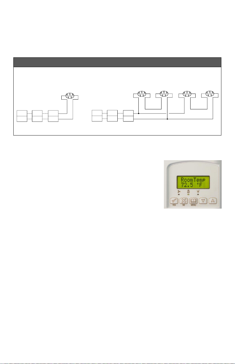
S2020E1000; outdoor air temperature sensor
WIRING S2000D1000, S2060A1000 and S2020E1000
Remote wiring 1 sensor Remote wiring 4 sensors
10 K
10 K
10 K
10 K
10 K
Scom
DS
Scom
OS
Scom
RS
or
or
Scom
DS
Scom
OS
Scom
RS
or
or
This sensor can be used for:
Outside air temperature sensing with the sensor installed directly exposed to
the elements.
Sensor uses a water resistant NEMA 4 ABS enclosure for outdoor
applications.
CONFIGURING AND STATUS DISPLAY INSTRUCTIONS
Status display
The Terminal Equipment Controller features a two-line, eightcharacter display. There is a low backlight level that is always
active and can only be seen at night.
When left unattended, the Terminal Equipment Controller has
an auto scrolling display that shows the current status of the
system.
Each item is scrolled sequentially with the back lighting in low level mode. Pressing any
key will cause the back light to come on to high level.
Manual scroll of each menu item is achieved by pressing the Yes (scroll) key repetitively.
The last item viewed will be shown on the display for 30 seconds before returning to
automatic scrolling. Temperature is automatically updated when scrolling is held.
9 | VZ7656E1000W Installation Guide
Page 10
Sequence of auto-scroll status display:
CLOCK
STATUS
SYSTEM
MODE
SCHEDULE
STATUS
OUTDOOR
TEMPERATURE
ALARMS
Monday
12:00
AM
Sys mode
auto
Occupied
Outdoor
x.x °C or°F
DAS Alarm
Sys mode
off
Occupied
hold
FA Alarm
Sys mode
heat
Unoccup
SetClock
Sys mode
cool
High CO2
Com Lost
Clock
Status
System
Mode
Schedule
Status
Outdoor
Temperature
Alarms
(if detected)
Monday
Sys Mode
Occupied
Outdoor
Service
12:00
AM
Off xx.x °C or °F
DAS Alrm
Sys Mode
Unoccupied
SetClock
Auto Filter
Sys Mode
Override
Comm Lost
Cool
Sys Mode
Heat
Outdoor air temperature
Outdoor air temperature display is only enabled when outdoor air temperature sensor is
connected.
A maximum range status display of 50 °C (122 °F) indicates a shorted sensor.
Associated functions, such as mode lockouts and economizer function are
automatically disabled.
A minimum range status -40 °C (-40 °F) is not displayed and indicates a opened
sensor or a sensor not connected. Associated functions, such as mode lockouts and
economizer function are automatically disabled.
Alarms
If alarms are detected, they will automatically be displayed at the end of the status
display scroll.
During an alarm message display, the back lit screen will light up at the same time as
the message and shut off during the rest of the status display.
Two alarms maximum can appear at any given time.
The priority for the alarms is as follows:
Sequence of manual-scroll status display:
Manual scroll of each menu item is achieved by pressing the Yes (scroll) key repetitively. The
last item viewed will be shown on the display for 30 seconds before returning to automatic
scrolling. Temperature is automatically updated when scrolling is held.
10 | VZ7656E1000W Installation Guide
Page 11

Current
Zone
Sequence
Return Air
Temperature
Discharge
Air
Temperature
Current Static
Pressure
Fresh Air
Level
Zone Seq
RA Temp
DA Temp
Pressure
FA Level
Off xx.x °C or °F
xx.x °C or °F
x.x WC or Pa
xxxxxCFM
Zone Seq
Cool
Zone Seq
Heat
Effective
PI Heat
Demand
at RTU
Effective
PI Cool
Demand
at RTU
Effective
CO2 Level
at RTU
Highest PI
Heat
Demand
Zone
Address
Highest PI
Cool
Demand
Zone
Address
Highest
CO2 Level
Zone
Address
Heat Out
Cool Out
CO2 Lvl
Heat MAC
Cool MAC
CO2 MAC
xxx %
xxx %
xxxx ppm
xxx xxx xxx
DAS
Alarm
Indicates that the discharge air temperature is either too low or too high.
FA Alarm
Indicates that the Fresh Air Level is either too low or too high.
SetClock
Indicates that the clock needs to be reset. There has been a power failure
which has lasted longer than 6 hours.
High CO2
Indicates that the CO2 Level value is higher than the Max CO2 parameter
value.
Com Lost
The communication between devices has been lost (No Communication)
When any of the fan is ON, the FAN LED will illuminate
When heating is ON, the HEAT LED will illuminate
When cooling is ON, the COOL LED will illuminate
USER INTERFACE
User configuring instructions menu
The VZ7656 series of controllers feature an intuitive,
menu-driven, back-lit LCD display that walks users and
installers through the configuring steps, making the
configuring process extremely simple. This menu is
typically accessed by the user to set the parameters
such as the clock time set, the schedule time events
and the system mode.
11 | VZ7656E1000W Installation Guide
Page 12

It is possible to bring up the user menu at any time by depressing the MENU key. The
Ex.:
Press yes key to change cooling temperature setpoint
Use the up or down arrow to adjust cooling setpoint
The YES key is used to confirm a selection, to move onto the next menu item
and to manually scroll through the displayed information.
The NO key is used when you do not desire a parameter change, and to
advance to the next menu item. Can also be used to toggle between heating
and cooling setpoints.
The MENU key is used to access the Main User Menu or exit the menu.
The down arrow key is used to decrease temperature setpoint and to adjust
the desired values when configuring the Terminal Equipment Controller.
The up arrow key is used to increase temperature setpoint and to adjust the
desired values when configuring the Terminal Equipment Controller.
Override
Resume
System mode
setting
Schedules
setting
Clock setting
Override
schd Y/N
Sys mode
set Y/N
Schedule
set Y/N
Clock
set Y/N
Appears only in
unoccupied mode
Cancel
ovrd Y/N
Appears only in
override mode
status display automatically resumes after exiting the user-configuring menu.
If the user pauses at any given time during configuring, Auto Help text is displayed to
help and guide the user through the usage and configuring of the controller.
Each of the sections in the menu is accessed and configured using 5 keys on the
controller cover. The priority for the alarms is as follows:
Local keypad interface
When left unattended for 45 seconds, the display will resume automatic status
display scrolling.
To turn on the back light, press any key on the front panel. The back lit display will
turn off automatically after 45 seconds.
Sequence of user menu:
12 | VZ7656E1000W Installation Guide
Page 13

Override
schd Y/N
Cancel
ovrd Y/N
Sys mode
set Y/N
Sys mode
off
Off mode
Normal cooling or heating operation disabled.
Sys mode
auto
Automatic mode
Automatic changeover mode between heating and cooling operation
based on local zone demands voting for RTU system operation.
Sys mode
cool
Cooling mode
Cooling operation mode only
Sys mode
heat
Heating mode
Heating operation mode only
A) Override an unoccupied period
This menu will appear only when the controller is in unoccupied mode. The unoccupied
mode is enabled either by the internal timer scheduling or by a network unoccupied
command on the occupancy object.
If DI1 is configured to operate as a remote temporary override contact, this menu will be
disabled.
Answering yes to this prompt will cause the all the zones attached to the RTU controller to
go into occupied mode for an amount of time equal to the parameter “TOccTime” (1 to 12
hours).
B) Resume regular scheduling
This menu does not appear in regular operation. It will appear only when the controller is
in override mode.
Answering “Yes” to this question will cause all the zones attached to the RTU controller to
resume the regular configured scheduling of the RTU controller schedule.
C) System mode setting
This menu is accessed to set system mode operation. Use ▲▼ to set value, yes key to
confirm.
13 | VZ7656E1000W Installation Guide
Page 14

D) Schedule set (2 events)
Schedule
set Y/N
MONDAY TIMER
SCHEDULE SET
TUESDAY
TIMER
SCHEDULE SET
WEDNESDAY
TIMER
SCHEDULE SET
OTHER DAYS ARE
IDENTICAL
Monday
set? Y/N
No next
Yes down
Tuesday
set? Y/N
No next
Yes down
Wednesda
set? Y/N
No next
Yes down
Selects the day to be scheduled or
modified
Yes key to access day scheduling, No key to jump to next day
Occupied
Day? Y/N
No next
Yes down
Occupied
Day? Y/N
No next
Yes down
Occupied
Day? Y/N
No next
Yes down
Yes = Daily schedules will be
accessed
No = Unoccupied mode all day
Yes key to access day scheduling, No key to jump to next day
Copy Y/N
Previous
Yes next
No down
Copy Y/N
Previous
Yes next
No down
Yes = Will copy previous day
schedule
No = Daily schedules will be
accessed
Yes key to copy previous day, No key to set new time value for each day
Occupied
00:00 AM
Use ▲▼
To set
value
Occupied
00:00 AM
Use ▲▼
To set
value
Occupied
00:00 AM
Use ▲▼
To set
value
Sets Event # 1 Occupied time
Will activate occupied setpoints
Use ▲▼ to set value, Yes key to confirm
Unoccup
00:00 AM
Use ▲▼
To set
value
Unoccup
00:00 AM
Use ▲▼
To set
value
Unoccup
00:00 AM
Use ▲▼
To set
value
Sets Event # 2 Unoccupied time
Will activate unoccupied setpoints
Use ▲▼ to set value, Yes key to confirm
Event
Period #1 - Event #1
Period #1 - Event #2
Occupied
Unoccupied
Daily Occupancy
Monday
7.00 AM
6.00 PM
Day time only
Tuesday
7.00 AM
6.00 PM
Day time only
Wednesday
7.00 AM
6.00 PM
Day time only
Thursday
7.00 AM
6.00 PM
Day time only
Friday
7.00 AM
6.00 PM
Day time only
Saturday
12.00 PM *
12.00 PM *
Unoccupied
Sunday
12.00 PM *
12.00 PM *
Unoccupied
Note: 12:00 PM = Noon
12:00 AM = Midnight
Scheduling can have 2 or 4 events per day. This is set in the configuration menu as per
parameter; (2/4event).
This section of the menu permits the user to set the weekly schedule for all the zones
attached to the RTU controller. Each day can be tailored to specific schedules if needed.
2 events can be configured per day.
Occupied & unoccupied periods can be set for each day.
Typical examples of a 2 event office schedule
Ex. #1 Office building closed all weekend
* Configuring consecutive events to the same time will cause the controller to choose the
last event as the time at which it will set its schedule. In the above example, the
controller will control the unoccupied set point until 7:00 AM Monday.
14 | VZ7656E1000W Installation Guide
Page 15

Ex. #2 Commercial building which is occupied all weekend
Event
Period #1 - Event
#1
Period #1 - Event
#2
Occupancy
Occupied
Unoccupied
Daily
Occupancy
Monday
8.00 AM
5.00 PM
Day time only
Tuesday
8.00 AM
5.00 PM
Day time only
Wednesday
8.00 AM
5.00 PM
Day time only
Thursday
8.00 AM
5.00 PM
Day time only
Friday
8.00 AM
5.00 PM
Day time only
Saturday
12.00 AM **
11.59 PM **
Occupied
Sunday
12.00 AM **
11.59 PM **
Occupied
Schedule
set Y/N
Monday timer
Schedule set
Tuesday timer
Schedule set
Wednesday timer
Schedule set
Other days are identical
Monday
set? Y/N
No next
Yes down
Tuesday
set? Y/N
No next
Yes down
Wednesda
set? Y/N
No next
Yes down
Selects the day to be scheduled or
modified
Yes key to access day scheduling, No key to jump to next day
Occupied
Day? Y/N
No next
Yes down
Occupied
Day? Y/N
No next
Yes down
Occupied
Day? Y/N
No next
Yes down
Yes = Daily schedules will be
accessed
No = Unoccupied mode all day
Yes key to access day scheduling, No key to jump to next day
Copy Y/N
Previous
Yes next
No down
Copy Y/N
Previous
Yes next
No down
Yes = Will copy previous day
schedule
No = Daily schedules will be
accessed
Yes key to copy previous day, No key to set new time value for each day
Occupied
00:00 AM
Use ▲▼
To set
value
Occupied
00:00 AM
Use ▲▼
To set
value
Occupied
00:00 AM
Use ▲▼
To set
value
Sets Event # 1 Occupied time
Will activate occupied setpoints
Use ▲▼ to set value, Yes key to confirm
Unoccup
00:00 AM
Use ▲▼
To set
value
Unoccup
00:00 AM
Use ▲▼
To set
value
Unoccup
00:00 AM
Use ▲▼
To set
value
Sets Event # 2 Unoccupied time
Will activate unoccupied
setpoints
Use ▲▼ to set value, Yes key to confirm
Occupie2
00:00 AM
Use ▲▼
To set
value
Occupie2
00:00 AM
Use ▲▼
To set
value
Occupie2
00:00 AM
Use ▲▼
To set
value
Sets Event # 3 Occupied time
Will activate occupied setpoints
Use ▲▼ to set value, Yes key to confirm
Unoccup2
00:00 AM
Use ▲▼
To set
value
Unoccup2
00:00 AM
Use ▲▼
To set
value
Unoccup2
00:00 AM
Use ▲▼
To set
value
Sets Event # 4 Unoccupied time
Will activate unoccupied
setpoints
Use ▲▼ to set value, Yes key to confirm
**To schedule a day as occupied for 24 hours, set that day occupied time to
12:00 AM and Unoccupied time to 11:59 PM There will be a 1 minute unoccupied
period every night at 11:59 PM with this schedule configuration
E) Schedule set (4 events)
This section of the menu permits the user to set the weekly schedule for all the zones
attached to the RTU controller. Each day can be tailored to specific schedules if
needed.
4 events can be configured per day.
Occupied & Unoccupied periods can be set for each day.
Scheduling the 3 rd. & 4 th. events to the same time will cancel the last period.
15 | VZ7656E1000W Installation Guide
Page 16

Ex. #1. Four event retail establishment schedule
Event
Period 1 -
Event 1
Period 1 -
Event 2
Period 2 -
Event 3
Period 2 -
Event 4
Occupancy
Occupied
Unoccupied
Occupied
Unoccupied
Cool
Heat
Cool
Heat
Cool
Heat
Cool
Heat
Daily
72°F
70°F
80°F
62°F
72°F
70 °F
80°F
62 °F
Occupancy
Monday
7.00 AM
5.00 PM
12.00 PM *
12.00 PM *
Day time only
Tuesday
7.00 AM
5.00 PM
12.00 PM *
12.00 PM *
Day time only
Wednesday
7.00 AM
5.00 PM
12.00 PM *
12.00 PM *
Day time only
Thursday
7.00 AM
5.00 PM
7.00 PM
10.30 PM
Day/evening
time only
Friday
7.00 AM
5.00 PM
7.00 PM
10.30 PM
Day/evening
time only
Saturday
12.00 PM *
12.00 PM *
12.00 PM *
12.00 PM *
Unoccupied
Sunday
12.00 PM *
12.00 PM *
12.00 PM *
12.00 PM *
Unoccupied
Clock
set Y/N
Time setting
Day setting
Time format setting
Time
set? Y/N
No next
Yes down
Day
set? Y/N
No next
Yes down
12/24hrs
set? Y/N
No = exit
Yes down
Time
0:00
Use ▲▼
To set value
Day
Monday
Use ▲▼
To set value
12/24hrs
12 hrs
Use ▲▼
To set value
* Scheduling events to the same time will cancel the last period and leave the
controller in unoccupied mode.
F) Clock/Day Settings
This section of the menu permits the user to set the time and day.
INSTALLER CONFIGURATION PARAMETER MENU
Configuration can be done through the network or locally at the Terminal Equipment
Controller.
To enter configuration, press and hold the middle button “Menu” for 8 seconds
If a password lockout is active, “Password” is prompted. Enter password value using the
“up” and “down” arrows and press “Yes” to gain access to all configuration properties of
the Terminal Equipment Controller. A wrong password entered will prevent local access to
the configuration menu.
Once in the configuration menu, press the “No” button repetitively to scroll between all the
available parameters.
When the desired parameter is displayed, press “Yes” to adjust it to the desired value
using “up” and “down” arrows. Once set, press “Yes” to scroll to the next parameter.
16 | VZ7656E1000W Installation Guide
Page 17

CONFIGURATION
PARAMETERS
DEFAULT VALUE
SIGNIFICANCE AND ADJUSTMENTS
PswrdSet
Configuration parameters
menu access password
Default value = 0
No password prompted
This parameter sets a password access to prevent
unauthorized access to the configuration menu
parameters. A default value of “0” will not prompt a
password or lock the access to the configuration
menu.
Range is: 0 to 1000
RTC MAC
Zone Controller Controller
network address
Default Value: 4
RTC MAC address must be unique for the entire
network.
1 to 255 (Increments: 1 or 10)
For Zigbee™ models valid range to use is from 1 to
127.
PAN ID
Personal Area Network
Identification
Default value = 0
Range is: 0 to 500
This parameter (Personal Area Network Identification) is
used to link specific controllers to a single specific
Viconics wireless gateway ( VWG / Jace-Driver ) or a
specific VZ76 RTU controller. For every controller
reporting to a VWG / Jace-Driver or VZ76 controller, be
sure you set the SAME PAN ID value.
The default value of 0 is NOT a valid PAN ID. The valid
range of available PAN ID is from 1 to 500
17 | VZ7656E1000W Installation Guide
Page 18

When PAN ID is used with a range of 251 to 500, for (SA) Stand-Alone Systems
RTU VZ76 Coordinator
Channel 25 ID
200
Zone VZ72 Router
Channel 25 ID
200
Zone VZ72 Router
Channel 25 ID
200
Zone VZ72 Router
Channel 25 ID
200
Zone VZ72 Router
Channel 25 ID
200
System 1
RTU VZ76 Coordinator
Channel 25 ID
205
Zone VZ72 Router
Channel 25 ID
205
Zone VZ72 Router
Channel 25 ID
205
Zone VZ72 Router
Channel 25 ID
205
Zone VZ72 Router
Channel 25 ID
205
System 2
In this application, the VZ76 controller(s) are the coordinators to their own system. I.E.
they are the network masters for each VZ72 controller reporting to them.
Wireless controller factory default Channel & PAN ID = Controller(s) offline
VZ76 RTU controller is the network coordinator.
Range of PAN ID on all controllers to use 251 to 500. This range is reserved for
stand-alone system operation.
Examples:
Notes:
Each system with a VZ76 RTU master will use a unique PAN ID and / or Channel settings.
18 | VZ7656E1000W Installation Guide
Page 19

When PAN ID is used with a range of 1 to 250, for (NS) Networked Systems
Coordinator
Channel 25 ID
200
RTU VZ76 Router
Channel 25 ID
200
Zone VZ72 Router
Channel 25 ID
200
Zone VZ72 Router
Channel 25 ID
200
Zone VZ72 Router
Channel 25 ID
200
Zone VZ72 Router
Channel 25 ID
200
System 1
System 2
RTU VZ76 Router
Channel 25 ID
200
Zone VZ72 Router
Channel 25 ID
200
Zone VZ72 Router
Channel 25 ID
200
Zone VZ72 Router
Channel 25 ID
200
Zone VZ72 Router
Channel 25 ID
200
In this application, any controller(s) are simply router to the system. The VWG / JaceDriver is the coordinators to the system. I.E. the VWG / Jace-Driver is the network
masters for ANY controller(s) reporting to them.
Wireless controller factory default Channel & PAN ID = Controller(s) offline
VWG Jace-Driver is the network coordinator
Any controllers ( VZ72’s, VZ76xx RTU’s or any VT7xxx wireless controllers ) act
as routers.
Range of PAN ID on all controllers to use 1 to 250. Reserved for networked
system operation.
Examples:
Notes:
Each controller(s) to use same PAN ID and Channel as VWG Jace-Driver
coordinator.
VWG / Jace-Driver supports network integration for required GUI / System /
Status objects.
19 | VZ7656E1000W Installation Guide
Page 20

Channel
Channel selection
Default value = 10
Range is: 10 to 26
This parameter (Channel) is used to link specific
controllers to specific Viconics wireless gateway(s)
(VWG / Jace-Driver) or to the main VZ76xx RTU
controller. For any system, be sure you set the SAME
channel value both at the network coordinator and on all
the VZ72xx controller(s).
Viconics recommends using only the following channels:
15, 25 & 26.
The default value of 10 is NOT a valid channel. The valid
range of available channels range from 11 to 26.
Lockout Keypad lockout levels
Default value = 0 No lock
0 = No lock
1 = Low level
2 = High level
USER KEY FUNCTIONS
LEVEL
Global Unocc Override
System mode setting
Schedules setting
Clock setting
0
1
2
pwr del
Power-up delay
Default value = 10 seconds
On initial power up of the Terminal Equipment Controller
(each time 24 VAC power supply is removed & reapplied) there is a delay before any operation is
authorized (fan, cooling or heating). This can be used to
sequence start up multiple units / Terminal Equipment
Controller in one location.
10 to 120 seconds
20 | VZ7656E1000W Installation Guide
Page 21

CntrlTyp
Sets how the Zones attached
to the RTU controller vote to
determine the actual system
mode of operation.
(Heat or Cool)
Default Value:
1 = AV_H3
This parameter will select the type of operation required
for the RTU based on the size of the system. Please refer
to the Viconics Zoning System Guide for recommended
settings.
Only the Zones that actually have values above 0% in
their (PIHT Wei & PICL Wei) configuration parameters
will be able to vote on the RTU operational mode
calculation.
0 =Highest: The highest PI Heating or PI Cooling
demand from the selected voting zones will dictate
heating or cooling operation of the RTU controller.
1 = AV_H3: The average of the 3 highest PI Heating or PI
Cooling demands from the selected voting zones will
dictate heating or cooling operation of the RTU controller.
2 = AV_H5: The average of the 5 highest PI Heating or
PI Cooling demands from the selected voting zones will
dictate heating or cooling operation of the RTU controller.
Dis HL
Discharge air temperature
high limit
Default: 120°F
Discharge air high temperature value at which the heating
stages will be locked out.
70°F to 150°F (21°C to 65°C)
(increments: 0.5° or 5°)
Dis LL
Discharge air temperature low
limit
Default: 45°F
Discharge air low temperature value at which the cooling
stages will be locked out.
35 to 65°F (2.0°C to 19.0°C)
(increments: 0.5° or 5°)
Anticycl
Minimum On-Off operation
time for stages
Default value = 2 minutes.
Minimum On-Off operation time of cooling & heating
stages.
IMPORTANT, anti-short cycling can be set to 0 minutes
for equipment that possess their own anti cycling timer.
Do not use this value unless the equipment has the above
mentioned internal timer. Failure to follow this guideline
may lead to damaged equipment.
0, 1, 2, 3, 4 & 5 minutes.
Heat cph
Heating stages cycles per
hour
Default value = 4 C.P.H.
Will set the maximum number of heating stage cycles per
hour under normal control operation. It represents the
maximum number of cycles that the equipment will be
turned on and off in the span of an hour.
Note that a higher C.P.H will represent a higher accuracy
of control at the expense of wearing down mechanical
components faster.
3, 4, 5, 6,7 & 8 C.P.H.
21 | VZ7656E1000W Installation Guide
Page 22

Cool cph
Cooling stages cycles per
hour
Default value = 4 C.P.H.
Will set the maximum number of cooling stage cycles per
hour under normal control operation. It represents the
maximum number of cycles that the equipment will be
turned on and off in the span of an hour.
Note that a higher C.P.H will represent a higher accuracy
of control at the expense of wearing down mechanical
components faster.
3 or 4 C.P.H.
Deadband
Minimum deadband
Default value = 2.0 °F (1.1 °C)
Minimum deadband value between the heating and
cooling setpoints.
Used only with the setpoints used during communication
failure (ComLost Alarm) while operation is under the
return air sensor. If modified, it will be applied only when
any of the setpoints are modified.
2, 3 or 4 °F ( 1.0 to 2.0 °C )
Units
Sets the display scale of the
controller
Default value = Imp
0 = SI for Celsius / Pa pressure scale.
1 = Imp for Fahrenheit / in. WC pressure scale.
fan del
Fan delay
Default value = Off
Fan delay extends fan operation by 60 seconds after the
call for heating or cooling ends.
Valid only for Auto fan mode. “On” fan mode will leave the
fan always on.
Off or On
CO2 ctrl
CO2 Control Type
configuration
Default value = AV_H3
Determines the value of CO2 to be used for control of the
fresh air damper.
Highest: The highest value among the zones with CO2
sensors is used.
AV_H3: The average of the three highest values among
the zones with CO2 sensors is used.
AV_H5: The average of the 5 highest values among the
zones with CO2 sensors is used.
ToccTime
Temporary occupancy time
Default value = 3 hours
Temporary occupancy time with occupied mode setpoints
when override function is enabled
When the Terminal Equipment Controller is in unoccupied
mode, function is enabled with either the menu or DI1 or
DI2 configured as remote override input.
0,1, 2, 3, 4, 5, 6, 7, 8, 9, 10, 11 & 12 hours
Cal RS
Room air temperature sensor
calibration
Default value = 0.0 °F or °C
Offset that can be added/subtracted to actual displayed
room temperature
± 5.0 °F ( ± 2.5 °C )
22 | VZ7656E1000W Installation Guide
Page 23

Cal OS
Outside air temperature
sensor calibration
Default value = 0.0 °F or °C
Offset that can be added/subtracted to actual displayed
outside air temperature
± 5.0 °F ( ± 2.5 °C )
H stage
Number of heating stages
installed at RTU.
Default value = 2 stages
Will revert the operation of 2 stage controllers to a single
stage when the second heating step is not needed.
1 or 2 stages
C stage
VZ7656R1000B models only
Number of cooling stages
installed at RTU.
Default value = 2 stages
Will revert the operation of 2 stage controllers to a single
stage when the second cooling step is not needed.
1 or 2 stages
H lock
Outside air temperature
heating lockout
Default value = 120 °F (49
°C)
Disables heating stage operation based on outdoor air
temperature.
Function will only be enabled if OS ( outside air
temperature sensor ) is connected.
From -15 °F up to 120 °F (-26 °C up to 49 °C)
C lock
Outside air temperature
mechanical cooling lockout.
Default value = -40 °F (40 °C)
Disables cooling stage operation based on outdoor air
temperature.
On economizer model, free cooling will not be disabled by
this function.
Function will only be enabled if OS (outside air
temperature sensor) is connected.
From -40 °F up to 95 °F ( -40 °C up to 35 °C )
2/4event
Number of events
configuration
Default value = 2 event
2 events, will set up scheduling for the following
Event 1 is for Occupied setpoints
Event 2 is for Unoccupied setpoints
4 events, will set up scheduling for the following
Event 1 is for Occupied setpoints
Event 2 is for Unoccupied setpoints
Event 3 is for Occupied setpoints
Event 4 is for Unoccupied setpoints
FA Range
FA range upper limit value
Default value = 0 CFM
Sets the upper limit of the CFM range. This parameter
should be set based on the rooftop unit size. If set to 0
CFM, the fresh air damper control will be based on the
Min/Max CO2 and Min/Max Pos values. See Damper
Position section for more details.
0 to 20 000 CFM (0 to 9438 L/s), 10 or 100 increments
23 | VZ7656E1000W Installation Guide
Page 24

Prog rec
Progressive recovery enabled
Default value = Off
Progressive recovery is
automatically disabled if BI 1
is configured remote NSB
Off, = no progressive recovery.
The programmed occupied schedule time is the time at
which the system will restart and send the occupied status
to the attached zones.
On, = progressive recovery active.
The programmed occupied schedule time is the time at
which the desired occupied temperature setpoints will be
attained at the Zones. The RTU controller will
automatically optimize the equipment start time.
Occ CL
Return air sensor network
lost occupied heating
setpoint
Default: 72°F
If network communication is lost with the zone controllers,
the return air sensor will control the RTC to maintain this
setpoint.
40 to 90°F (4.5°C to 32°C)
(increments: 0.5° or 5°)
Occ HT
Return air sensor network lost
occupied heating setpoint
Default: 72°F
If network communication is lost with the zone controllers,
the return air sensor will control the RTC to maintain this
setpoint.
40 to 90°F (4.5°C to 32°C)
(increments: 0.5° or 5°)
Unocc CL
Return air sensor network lost
unoccupied cooling setpoint
Default: 82°F
If network communication is lost with the zone controllers,
the return air sensor will control the RTC to maintain this
setpoint.
54 to 100°F (12°C to 37.5°C)
(increments: 0.5° or 5°)
Unocc HT
Return air sensor network lost
unoccupied heating setpoint
Default: 65°F
If network communication is lost with the zone controllers,
the return air sensor will control the RTC to maintain this
setpoint.
40 to 90°F (4.5°C to 32°C)
(increments: 0.5° or 5°)
Sp range
Static Pressure sensor range
Default: 0
Static pressure transducer range. Voltage input range is 0
to 5 VDC.
0 = 0 to 1.5 in WC
1 = 0 to 2 in WC
2 = 0 to 3 in WC
3 = 0 to 4 in WC
4 = 0 to 5 in WC
24 | VZ7656E1000W Installation Guide
Page 25

Pressure
Static Pressure setpoint
Default: 0.8”WC
Bypass damper will maintain this supply static pressure
set point.
Please refer to the Viconics Zoning System Guide for
recommended settings.
0 to 2 in WC (0 Pa to 500 Pa)
(increments: 0.1” WC or 25 Pa)
SP Cntrl
Static Pressure Control Type
Default: BPD
Depending on the setting of this parameter, the 0-10VDC
pressure control output (labled BPD) will either have a
0VDC or 10VDC output when the fan is Off.
BPD (By-Pass Damper): 10VDC when fan Off
VFD (Variable Frequency Drive): 0VDC when fan Off
Chngstpt
changeover setpoint
Default value = 55 °F(13.0 °C)
In Cooling mode.
The outside air temperature value at which the cooling will
be switched over from mechanical ( compressor ) to free
cooling ( economizer )
14 to 70 °F ( -10.0 to 21.0 °C )
mix stpt
Mixed air setpoint
Default value = 55 °F ( 13.0
°C )
Free cooling mixed air setpoint when economizer mode is
enabled.
50 to 90 °F ( 10.0 to 32.0 °C )
Min Pos
Minimum Fresh Air
Damper/Economizer Position
Default value = 0%
Minimum fresh air damper position. Effective only in
Occupied mode (Fan is ON). This value is also used to
determine the fresh air damper position based on the
Min/Max CO2 and Min/Max Pos values set. See Fresh Air
Damper Position section for more details.
0% to 100%, 1 or 10 increments
Max Pos
Maximum Fresh Air
Damper/Economizer Position
Default value = 100%
Maximum fresh air damper position. Effective only in
Occupied mode (Fan is ON). This value is used to
determine the fresh air damper position based on the
Min/Max CO2 and Min/Max Pos values set. See Fresh Air
Damper Position section for more details.
0% to 100%, 1 or 10 increments
25 | VZ7656E1000W Installation Guide
Page 26

Min FA
Minimum Fresh Air Value
Default value = 0 CFM
Minimum fresh air required. Effective only in Occupied
mode (Fan is ON). This value is used to determine the
fresh air damper position based on the Min/Max CO2 and
Min/Max FA values (if FA Range is set to other than 0
CFM). See Fresh Air Damper Position section for more
details.
0 to 20 000 CFM (0 to 9438 L/s) (the value set cannot
exceed the value of FA Range parameter), 10 or 100
increments
Max FA
Maximum Fresh Air Value
Default value = 0 CFM
Maximum fresh air allowed. Effective only in Occupied
mode (Fan is ON). This value is used to determine the
fresh air damper position based on the Min/Max CO2 and
Min/Max FA values set (if FA Range is set to other than 0
CFM). See Fresh Air Damper Position section for more
details.
0 to 20 000 CFM (0 to 9438 L/s) (the value set cannot
exceed the value of FA Range parameter), 10 or 100
increments
Min CO2
Minimum CO2 Level
Default value = 800 ppm
Minimum CO2 Level required. Effective only in Occupied
mode (Fan is ON). This value is used to determine the
fresh air damper position based on the Min/Max CO2 and
Min/Max Pos values set. See Fresh Air Damper Position
section for more details.
0 to 2000 ppm, 10 or 100 increments
Max CO2
Maximum CO2 Level
Default value = 1200 ppm
Maximum CO2 Level allowed. Effective only in Occupied
mode (Fan is ON). This value is used to determine the
fresh air damper position based on the Min/Max CO2 and
Min/Max Pos values set. See Fresh Air Damper Position
section for more details.
0 to 2000 ppm, 10 or 100 increments
26 | VZ7656E1000W Installation Guide
Page 27

FRESH AIR DAMPER CONTROL SEQUENCES
The fresh air damper can be controlled through more than one sequence to achieve
different control strategies such as free cooling (economizer mode), minimum fresh air
control and CO2 level control. Here are the control sequences available:
Note: For the sequences mentioned below, the following conditions must be met in
order for the sequences to be performed as stated:
- Max Pos parameter value must be greater than Min Pos Parameter value.
- Mac CO2 parameter value must be greater than Min CO2 Parameter value.
- Max FA parameter value must be greater than Min FA Parameter value.
Economizer Control Mode Only
If the fresh air damper is to be used only for free cooling purposes (economizer mode,
without fresh air measurement station or CO2 control), only the Min Pos parameter and
the free cooling sequence will be active.
- The FA Range parameter should be set to 0 CFM. (Default Value = 0 CFM)
- Set the Chngstpt parameter to desired value which free cooling is enabled.
If the outside air temperature is greater than the changeover setpoint, then normal
mechanical cooling will be used. If the outside air temperature is less than or equal to the
changeover setpoint, then free cooling will be enabled and mechanical cooling stages will
be locked out.
(Default Value = 55°F)
27 | VZ7656E1000W Installation Guide
Page 28

Economizer Mode and Fresh Air Measurement Station
If the fresh air damper is to be used for both free cooling and minimum fresh air volume
control (economizer mode and fresh air measurement station, but without CO2 level
control), only the Min FA parameter and the free cooling sequence will be active.
- The FA Range parameter should be set to a value higher than 0 CFM (0
CFM disables the fresh air control).
- Min FA (minimum fresh air) parameter should be set to the desired level.
The FA Range parameter value should be set to the maximum capacity of the fresh air
measurement station. Therefore the relationship between air volumes and input signals
can be established. For example, if the fresh air station capacity is 10000 CFM, set FA
Range to 10000.
This will set the relationship of 0 VDC = 0 CFM and 10VDC = 10000 CFM.
28 | VZ7656E1000W Installation Guide
Page 29

Economizer Mode and CO2 Level Control
Min Pos
Max Pos
Min CO2
Max CO2
Current
Fresh Air
Setpoint
Current CO2 Level
If the fresh air damper is to be used for both free cooling and CO2level control
(economizer mode and CO2 level control, but without fresh air measurement station), only
the Min Pos, Max Pos, Min CO2and Max CO2 parameters as well as the free cooling
sequence will be active.
- The FA Range parameter should be set to 0 CFM.
- Set AI1 parameter to CO2 (0 VDC = 0ppm ; 10VDC = 2000ppm)
- Min Pos, Max Pos, Min CO2 and Max CO2 parameters should be set
according to the required setting.
The highest value between free cooling demand output and interpolation output
for the fresh air setpoint will be the output to the fresh air damper.
29 | VZ7656E1000W Installation Guide
Page 30

Economizer Mode, CO2 Level Control and Fresh Air Measurement Station
Min FA
Setpoint
Max FA
Setpoint
Min CO2
Max CO2
Current
FA Setpoint
Current CO2 Level
If the fresh air damper is to be used for both free cooling and CO2 level control with a fresh
air measurement station, only the Min FA, Max FA, Min CO2 and Max CO2 parameters as
well as the free cooling sequence will be active.
- The FA Range parameter should be set to something other than 0 CFM.
- Use an air flow transmitter to read fresh air level with AI2 input (0-5 VDC
input)
- Min FA, Max FA, Min CO2 and Max CO2 parameters should be set according
to the required setting.
THE HIGHEST VALUE BETWEEN FREE COOLING DEMAND OUTPUT AND INTERPOLATION OUTPUT
FOR THE FRESH AIR SETPOINT BASED ON THE CO2 LEVEL WILL BE THE OUTPUT TO THE FRESH
AIR DAMPER
30 | VZ7656E1000W Installation Guide
Page 31

SPECIFICATIONS
Terminal Equipment Controller power
requirements:
Operating conditions:
Storage conditions:
Sensor:
Resolution:
Temperature control accuracy:
Contact output rating
Occ, Stand-By and Unocc cooling setpoint range:
Occ, Stand-By and Unocc heating setpoint range:
Room and outdoor air temperature display range:
Supply air temperature range:
Static pressure and air flow analog inputs
Digital inputs:
By-Pass damper and economizer analog outputs
rating
By-Pass damper and economizer analog outputs
accuracy
Wire gauge:
Approximate shipping weight:
Agency Approvals all models:
Agency Approvals all models:
Agency Approvals Wireless models:
19-30 VAC 50 or 60 Hz; 2 VA Class 2
RC to RH jumper 2.0 Amps 48VA max.
0 °C to 50 °C ( 32 °F to 122 °F )
0% to 95% R.H. non-condensing
-30 °C to 50 °C ( -22 °F to 122 °F )
0% to 95% R.H. non-condensing
Local 10 K NTC thermistor
± 0.1 °C ( ± 0.2 °F )
± 0.5 ° C ( ± 0.9 °F ) @ 21 °C ( 70 °F )
typical calibrated
Relay outputs: 30 VAC, 1 Amp.
Maximum, 3 Amp. In-rush.
12.0 to 37.5 °C ( 54 to 100 °F )
4.5 °C to 32 °C ( 40 °F to 90 °F )
-40 °C to 50 °C ( -40 °F to 122 °F )
-40 °C to 65 °C ( -40 °F to 150 °F )
0-5 VDC across AI, SP, Scom
Dry contact across terminal DI1
0 to 10 VDC into 2K resistance min
± 3% typical
18 gauge maximum, 22 gauge
0.75 lb ( 0.34 kg )
UL: UL 873 (US) and CSA C22.2 No.
24 (Canada), File E27734 with CCN
XAPX (US) and XAPX7 (Canada)
Industry Canada: ICES-003 (Canada)
FCC: Compliant to CFR 47, Part 15,
Subpart B, Class A (US)
CE : EMC Directive 2004/108/EC
(Europe Union)
C-Tick: AS/NZS CISPR 22 Compliant
(Australia / New Zealand) Supplier
Code Number N10696
FCC: Compliant to: Part 15, Subpart B,
Class (US)
THIS DEVICE COMPLIES WITH PART 15 OF THE FCC RULES. OPERATION IS SUBJECT
TO THE FOLLOWING TWO CONDITIONS: (1) THIS DEVICE MAY NOT CAUSE HARMFUL
INTERFERENCE, AND (2) THIS DEVICE MUST ACCEPT ANY INTERFERENCE RECEIVED,
INCLUDING INTERFERENCE THAT MAY CAUSE UNDESIRED OPERATION
Please check with your local government for instruction on disposal of this product
31 | VZ7656E1000W Installation Guide
Page 32

DRAWING & DIMENSIONS
Viconics Technologies Inc.
Tel.: Fax: Toll free:
www.viconics.com
32 | VZ7656E1000W Installation Guide
 Loading...