

Page 1

VZ7260X5X00W
Zigbee™ Wireless Zone Terminal Equipment
Controller
Installation Guide
For Commercial Zoning Systems
July 27th, 2012 / 028-0329-R3
CONTENTS
Installation 2
Location 2
Installation 2
Theory of Operation 3
Features and benefits overview 3
Wireless System Overview 5
Terminal, Identifi cation and Function 6
Wiring 6
Typical Applications 7
Main outputs wiring 7
Remote sensor accessories 11
CO2 sensor wiri ng 12
Configuring and Status Displa y Inst ructions 13
Status display 13
User interface 14
User configuration menu 14
Local keypad interf ace 15
Installer Configuration Parameter M enu 15
AI4 Input for CO2 Sensor 29
Referenced Operational Control Curves 30
Specifications Error! Bookmar k not defined.
Drawing & Dimensions 38
1 | VZ7260W Series- Installation Guide
Page 2
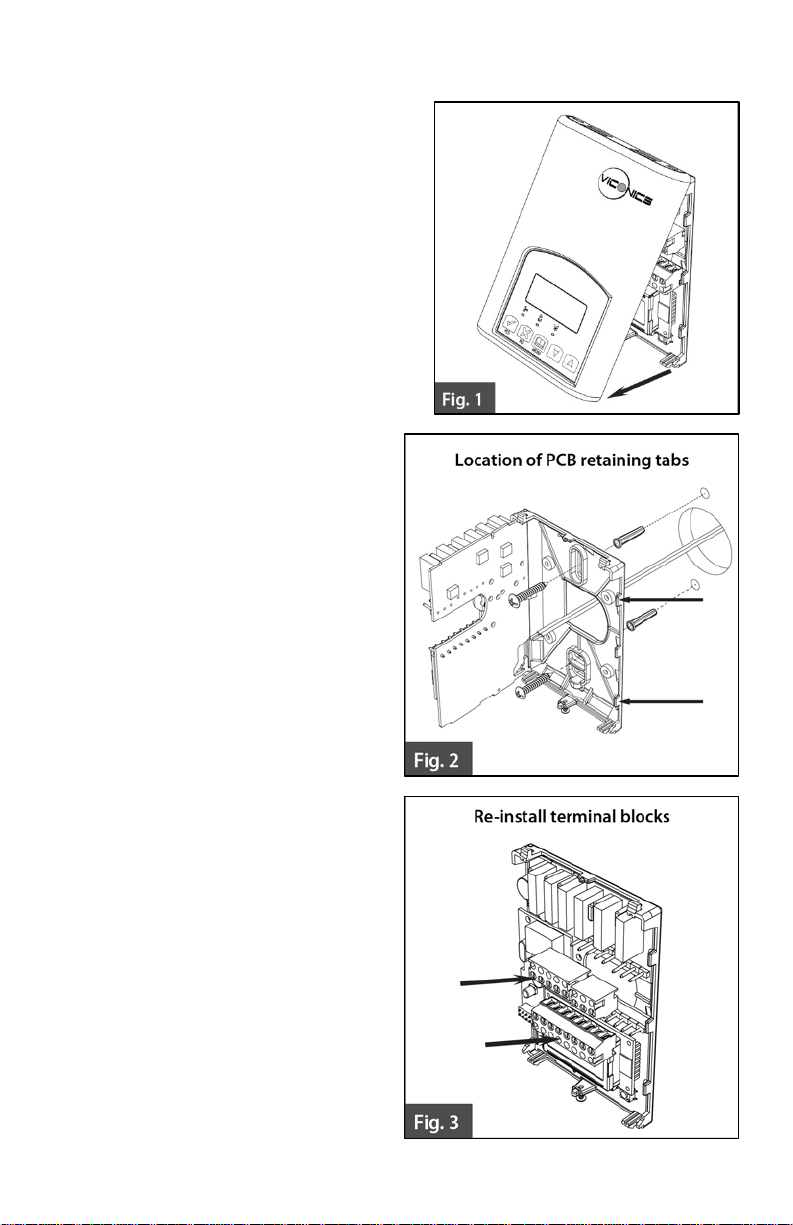
INSTALLATION
Remove the security screw on the bottom of
Terminal Equipment C ontroller cover.
Open unit by pulling on the bottom
side of Terminal Equipment
Controller (fig. 1).
Remove wiring terminal s from sticker .
Please read the FCC ID and IC label
installed in the cover upon removal of
cover for the wireless products.
Location
1. Should not be instal led on an outside
wall.
2. Must be installed away from any
direct heat source.
3. Should not be instal led near an
air discharge grill.
4. Should not be affected by direct
sun radiation.
5. Nothing should restrict vertical
air circulat ion to the Terminal
Equipment Controller.
Installation
1. Swing open the Terminal
Equipment Controller PCB to
the left by pressing the PCB
locking tabs (f ig. 2).
2. Pull out cables 6” out from the
wall.
3. Wall surface must be flat and
clean.
4. Insert cable in t he central hole
of the base.
5. Align the base and mark the
location of the tw o m ounting
holes on the wall. I nstall base in
the proper orientat ion. Arrow on
base should be facing up.
6. Install anchor s in the wall.
7. Insert screws in mounting holes
on each side of the bas e (f ig. 2) .
8. Gently swing back the circuit
board on the base and pus h on
it until the tabs lock it.
9. Strip each wire 1/4 inch from
end.
2 | VZ7260W Series- Installation Guide
Page 3
10. Insert each wire according to wiring diagr am .
11. Gently push excess w iring back into hole (fig. 3).
12. Re-Install wiri ng terminals in their c orrect locations (fig. 3).
13. Re-install the cover (top side first) and gent ly push extra wire length back into
the hole in the wall.
14. Install security screw.
When replacing an existing Terminal Equipment Controller, label the
wires before rem oval of the Terminal Equipment Controller.
Electronic controls are static sensitive devices. Dischar ge yourself
properly before manipulating and installing the Terminal Equi pment
Controller.
A short circuit or improper wiring may permanently damage the Terminal
Equipment Controller or the equipment.
All VT7000 series Terminal Equipment Controllers are desi gned for use
as operating controls only and are not saf ety devices. These inst ruments
have undergone rigorous tests and verifi cation prior to shipping to ensure
proper and reliabl e operation in the field. Whenever a control f ailure
could lead to personal injury and or loss of property, it becomes the
responsibili ty of the user or installer or electrical system designer to
incorporate safety devices (such as relays, flow s witch, thermal
protections, etc…) and or an alarm s ystem to protect the entir e system
against such catastrophic failures. Tampering with the devices or
unintended application of the devices w ill result in a void of warrant y.
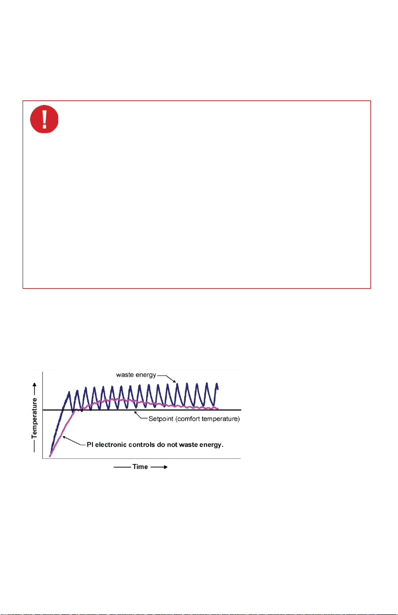
THEORY OF OPERATION
The VZ7260 series uses a Viconics proprietary adaptive logic algorithm to control the
space temperatur e. This algorithm c ontrols the heati ng and or air condit ioning system to
minimize oversho ot while still providing comf ort. It provides excepti onal accuracy due to
its unique PI time propor tioning control algorithm , which virtually eliminates t emperature
offset associated with traditional, differential-based On-Off thermostats.
Fig.2 - On-Off mechanical control vs. PI electronic control.
Features and benefits overview
• Available with analog or f loating outputs (model dependent).
• Adjustable Proportional Band.
• Password protected configuration menu.
• Removable terminal blocks.
• Hinged PC board design.
• EEPROM memory.
3 | VZ7260W Series- Installation Guide
Page 4

• PIR and Stand-by setpoints s upported.
• Local keypad lockable.
• PI time proportioning algorithm.
• Auxiliary output.
• Auto central system RTU changeover.
• Unique local configuration setup utility.
• C02 sensor input for monitor ing and control.
• Configurable zone sequences of operation.
• Pre-engineered design, sof tware and documentation.
• Self-discovering and self-binding database.
• Increased energy savings.
• Improves indoor air quality.
• Compatible with most actuator types (model dependent).
• No loss of program.
• Access to mounting holes.
• Facilitates wiring.
Easy configuration and self-binding operation
• Easy configurati on w ithout using any special software or additional tools.
• Can be used as stand-alone or with supervisi on controller for monitoring purposed.
• Truly scalable i n terms of supported number of zones and RTU units.
4 | VZ7260W Series- Installation Guide
Page 5
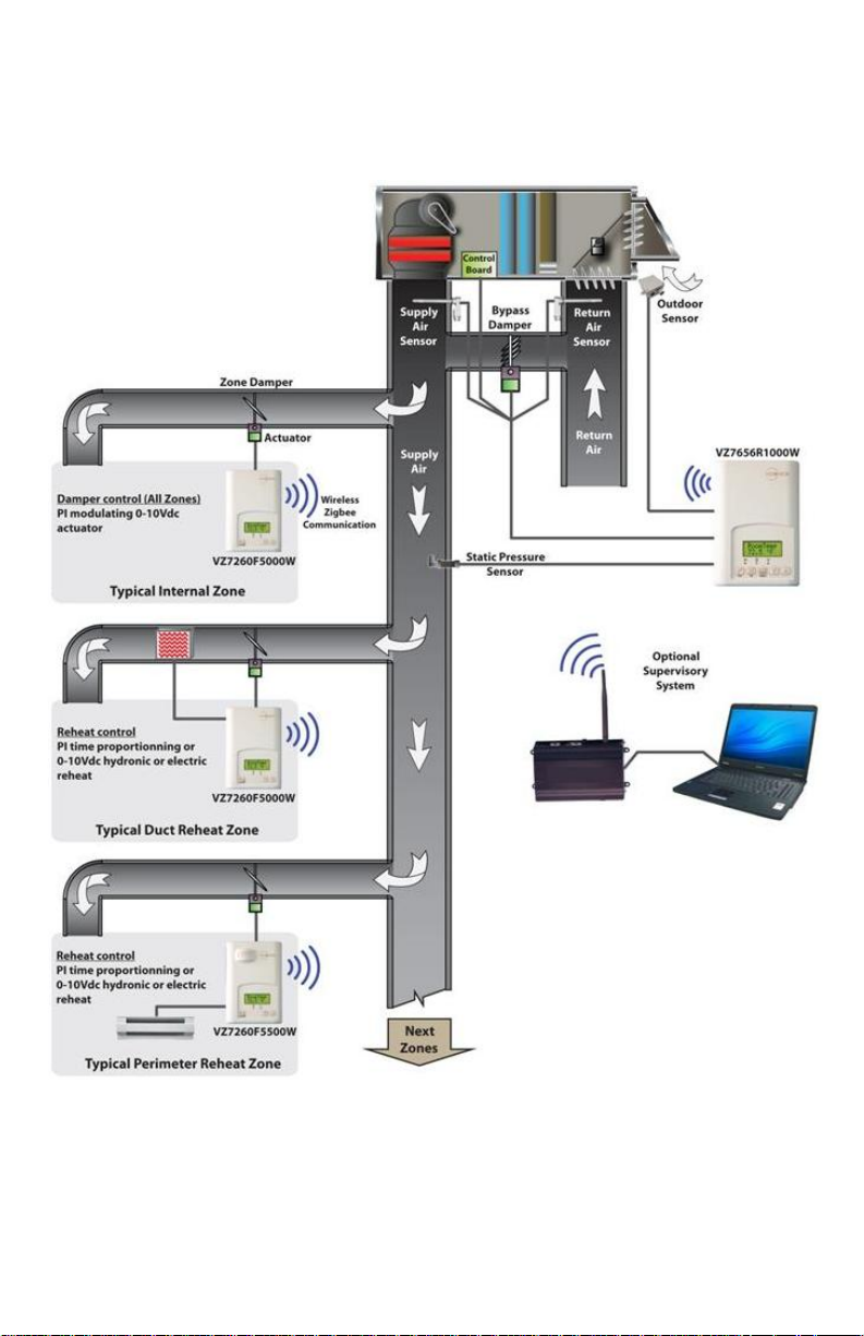
WIRELESS SYSTEM OVERVIEW
Viconics VZ7260X5x00W Zone controllers are used in conjunction with the
VZ7656X1000W Roof Top Controller controllers. Combined, the y are designed for typical
single or multis tage RTU, HP’s and their associated local zones.
Typical Wireless Zoning System Installation
5 | VZ7260W Series- Installation Guide
Page 6

TERMINAL, IDENTIFICATION AND FUNCTION
Terminal
VZ7260F
Terminal
VZ7260C
Wiring
Terminal Use
4 - 24 V ~ Hot
5 - 0 V ~ Com
6- On-Off Rht
7- On-Off Rht
8- Primary Rh t
9 – Primary
Rht
10 – VAV
Damper
11 – VAV
Damper
12 – BI1
13 – AI4
14 - Scom
15 - RS
16 – UI3 / SS
Identification
24V ~Hot 24V ~Hot
0V~Com 0V~Com
BO5 BO5
BO5 BO5
Not used
AO2 BO4
AO1 BO1
Not used BO2
BI1 BI1
AI4
Scom Scom
RS RS
UI3 UI3
Identification
BO3
AI4
Description
Power supply of controller, hot
side (De livered from t he RTU).
Power supply of controller,
common si de. Also used as
reference for the analog
outputs when used.
Local isolated triac reheat
output when used.
Local isolated triac reheat
output when used.
24 VAC triac reheat output
(open).
For VZ7260F: Local analog 0 -
10 VDC reheat output when
used.
For VZ7260C: 24VAC triac
reheat output (close).
For VZ7260F: Local VAV
analog 0 - 10 VDC.
For VZ7260C: 24VAC triac
VAV output (open).
For VZ7260C: 24VAC triac
VAV output (closed).
Configurable extra digital
input. See parameter section
for more in fo rmation.
0-10VDC analog input for
remote CO2 or other sensor
(airflow, etc...)
Reference input for BI 1, BI 2,
UI3 and RS.
Remote room sensor input
when used. Input auto-detects
a remote sensor and will
automatically by-pass the
internal sensor when used.
Non-configurable extra analog
input for monitoring local
discharge or supply
temperatures over the
network.
6 | VZ7260W Series- Installation Guide
Page 7
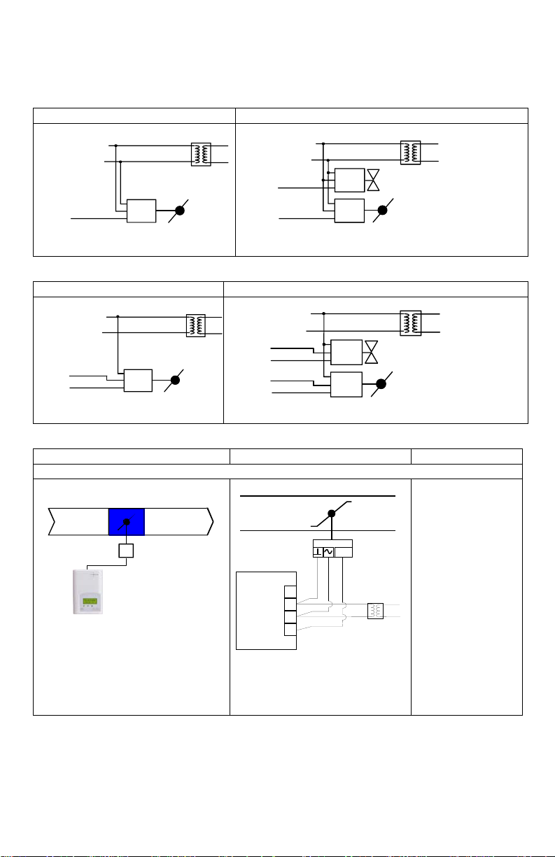
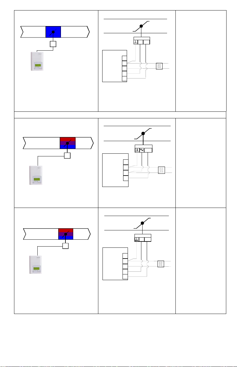
TYPICAL APPLICATIONS
VAV Damper Wiring
VAV Damper and Analog Reheat Wiring
VAV Damper Wiring
VAV Damper and Floating Reheat Wiring
Schematic
Wiring
Settings
Pressure dependent VAV cooling only system
Mandatory
VAV Damper
Motor
Com
24 VAC
0-10 VDC
24 V~ Hot
24 V~ Com
AO 1
24 V~ Hot
24 V~ Com
AO 2
AO 1
Com 24 VAC
0-10 VDC
Reheat Valve or SCR
VAV Damper Motor
Com
24 VAC
0-10 VDC
VAV Damper
Motor
Com
Open
Close
24 V~ Hot
24 V~ Com
BO 2
BO 1
24 V~ Hot
24 V~ Com
BO 4
BO 2
Com
Open
Close
Reheat Valve
VAV Damper Motor
Com
Open
Close
BO 3
BO 1
Analog VAV Actuator
Room Temperature Control
Minimum
& Maximum
Position
Adjusted at Controller
0 to 10
VDC
UI3
0 V~ Com
24 V~ Hot
AO1
Main outputs wiring
7 | VZ7260W Series- Installation Guide
RehtCon= 0 None
Page 8
Mandatory
RehtConf = 0 None
Pressure dependent VAV cooling or heating system with central changeover
Mandatory
Mandatory
Tri-State Floating
Actuator
Room Temperature Control
Minimum
& Maximum
Position
Adjusted at Controller
Floating VAV Actuator
Room Temperature Control
Minimum
& Maximum
Position
Adjusted at Controller
Close
UI3
0 V~ Com
24 V~ Hot
BO1
BO2
Open
0 to 10 Vdc
Analog Actuator
Room Temperature Control
Minimum
& Maximum
Position
Adjusted at Controller
0 to 10 VDC
UI3
0 V~ Com
24 V~ Hot
AO1
Close
UI3
0 V~ Com
24 V~ Hot
BO1
BO2
Open
RehtConf = 0 None
RehtConf = 0 None
8 | VZ7260W Series- Installation Guide
Page 9
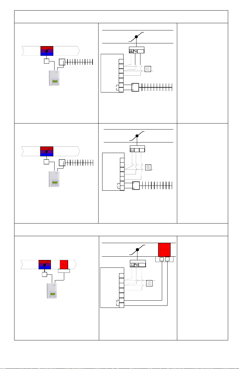
Pressure dependent VAV cooling or heating system with local On-Off perimeter
reheat and central changeover
Mandatory
RehtConf = 3 =
Mandatory
Pressure dependent VAV cooling or heating system with local On-Off duct
reheat and central changeover
Mandatory
Tri-State Floating VAV Actuator
Heating and/or Cooling
& On/Off Baseboard
Room Temperature Control
Minimum
& Maximum
Position
Adjusted at Controller
UI3
0 V~ Com
24 V~ Hot
BO1
BO5-Aux
BO5-Aux
BO2
R
Close
Open
Analog
VAV Actuator
Heating and/or Cooling
& On/Off Baseboard
Room Temperature Control
Minimum
& Maximum
Position
Adjusted at Controller
0 to 10
VDC
UI3
0 V~ Com
24 V~ Hot
AO1
BO5-Aux
BO5-Aux
AO2
R
Analog
VAV Actuator
Heating and/or Cooling
& On/Off Duct Heater
Room Temperature Control
Min, Max and HeatFlow
Positions Adjusted at Controller
1
C
0 to 10
VDC
UI3
0 V~ Com
24 V~ Hot
AO1
BO5-Aux
BO5-Aux
AO2
On-Off Perimeter
Reheat Only
Set BO5 Time to
0= 15 minutes if
using regular 24
VAC relays
Set BO5 Time to
1= 10 seconds if
using 24 VAC
Solid State Relays
(SSRs) for
proportional cont rol
RehtConf = 3 =
On-Off Perimeter
Reheat Only
Set BO5 Time to
0= 15 minutes if
using regular 24
VAC relays
Set BO5 Time to
1= 10 seconds if
using 24 VAC
Solid State Relays
(SSRs) for
proportional cont rol
RehtConf = 2 =
On-Off Duct
Reheat Only
Set BO5 Time to
0= 15 minutes if
using regular 24
VAC relays
Set BO5 Time to
1= 10 seconds if
using 24 VAC
Solid State Relays
(SSRs) for
proportional cont rol
9 | VZ7260W Series- Installation Guide
Page 10
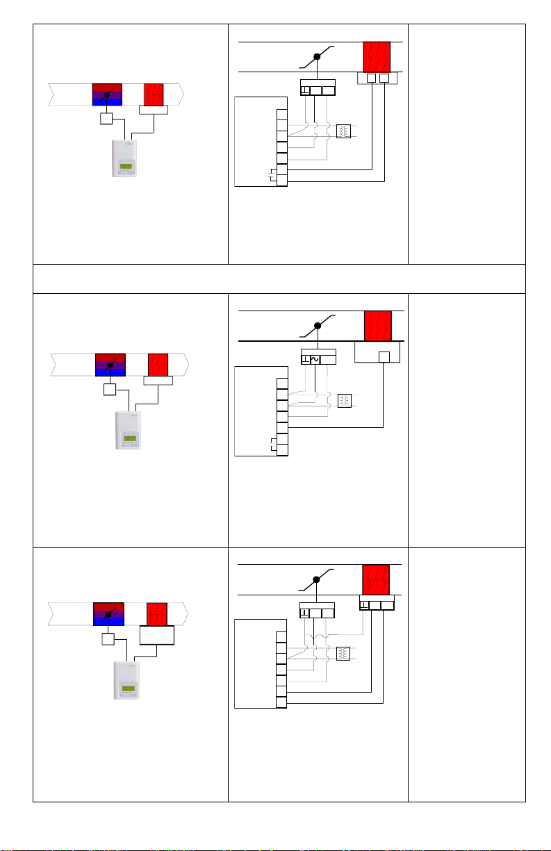
Mandatory
RehtConf = 2 =
Pressure dependent VAV cooling or heating system with local Analog duct
reheat and central changeover
Mandatory
Mandatory
Tri-State Floating VAV
Heating and/or Cooling
& Hot Water Reheat Valve
Room Temperature Control
Min, Max and HeatFlow
Positions Adjusted at Controller
Hot Water
Valve
Tri-State Floating VAV
Heating and/or Cooling
& On/Off Duct Heater
Room Temperature Control
Min, Max and HeatFlow
Positions Adjusted at Controller
UI3
0 V~ Com
24 V~ Hot
BO1
BO5-Aux
BO5-Aux
BO2
Close
Open
1
C
Analog
VAV Actuator
Heating and/or Cooling
& Analog Duct Heater
Room Temperature Control
Min, Max and HeatFlow
Positions Adjusted at Controller
SCR
SCR O-10VDC
Input
0 to 10
VDC
UI3
0 V~ Com
24 V~ Hot
AO1
BO5-Aux
BO5-Aux
AO2
UI3 0 V~ Com
24 V~ Hot
BO1
BO2
Close
Open
Close
Open
BO3
BO4
On-Off Duct
Reheat Only
Set BO5 Time to
0= 15 minutes if
using regular 24
VAC relays
Set BO5 Time to
1= 10 seconds if
using 24 VAC
Solid State Relays
(SSRs) for
proportional cont rol
RehtConf = 1 =
Analog Duct
Reheat Only
Set AO2RA/DA to
DA if SCR input
signal is Direct
Acting 0 to 10 VDC
Set AO2RA/DA to
RA if SCR input
signal is Reverse
Acting 10 to 0 VDC
RehtConf = 1 =
Analog Duct
Reheat Only
10 | VZ7260W Series- Installation Guide
Page 11
Remote sensor accessories
Model no.
Description
S3010W1000
Wall mounted temperature sensor
S2000D1000
Duct mounted temperature sensor
Fig.10 – Remote Duct Mounted Temperature Sensor
Remote mount temperature sensors use 10K NTC thermistor.
Temperature vs. Resistance Chart for 10 Kohm NTC Thermistor
(R
ºC ºF Kohm ºC ºF Kohm ºC ºF Kohm ºC ºF Kohm ºC ºF Kohm
-40 -40 324.3197 -20 -4 94.5149 0 32 32.1910 20 68 12.4601 40 104 5.3467
-39 -38 303.6427 -19 -2 89.2521 1 34 30.6120 21 70 11.9177 41 106 5.1373
-38 -36 284.4189 -18 0 84.3147 2 36 29.1197 22 72 11.4018 42 108 4.9373
-37 -35 266.5373 -17 1 79.6808 3 37 27.7088 23 73 10.9112 43 109 4.7460
-36 -33 249.8958 -16 3 75.3299 4 39 26.3744 24 75 10.4443 44 111 4.5631
-35 -31 234.4009 -15 5 71.2430 5 41 25.1119 25 77 10.0000 45 113 4.3881
-34 -29 219.9666 -14 7 67.4028 6 43 23.9172 26 79 9.5754 46 115 4.2208
-33 -27 206.5140 -13 9 63.7928 7 45 22.7861 27 81 9.1711 47 117 4.0607
-32 -26 193.9703 -12 10 60.3980 8 46 21.7151 28 82 8.7860 48 118 3.9074
-31 -24 182.2686 -11 12 57.2044 9 48 20.7004 29 84 8.4190 49 120 3.7607
-30 -22 171.3474 -10 14 54.1988 10 50 19.7390 30 86 8.0694 50 122 3.6202
-29 -20 161.1499 -9 16 51.3692 11 52 18.8277 31 88 7.7360 51 124 3.4857
-28 -18 151.6239 -8 18 48.7042 12 54 17.9636 32 90 7.4182 52 126 3.3568
-27 -17 142.7211 -7 19 46.1933 13 55 17.1440 33 91 7.1150 53 127 3.2333
-26 -15 134.3971 -6 21 43.8268 14 57 16.3665 34 93 6.8259 54 129 3.1150
-25 -13 126.6109 -5 23 41.5956 15 59 15.6286 35 95 6.5499 55 131 3.0016
-24 -11 119.3244 -4 25 39.4921 16 61 14.9280 36 97 6.2866 56 133 2.8928
-23 -9 112.5028 -3 27 37.5056 17 63 14.2629 37 99 6.0351 57 135 2.7886
-22 -8 106.1135 -2 28 35.6316 18 64 13.6310 38 100 5.7950 58 136 2.6886
-21 -6 100.1268 -1 30 33.8622 19 66 13.0307 39 102 5.5657 59 138 2.5926
= 10KΩ±3% - B
25°C
= 3975K±1.5%)
25/85°C
S2000D1000; remote duct mounted temperature sensor c/w junction box.
This sensor can be us ed for:
• Remote return air temperature
sensing with the sensor
mounted on the return air duct.
• Outside air temperature sensing
with the sensor installed in the
fresh air plenum.
• Supply air temperature sensing.
11 | VZ7260W Series- Installation Guide
Page 12
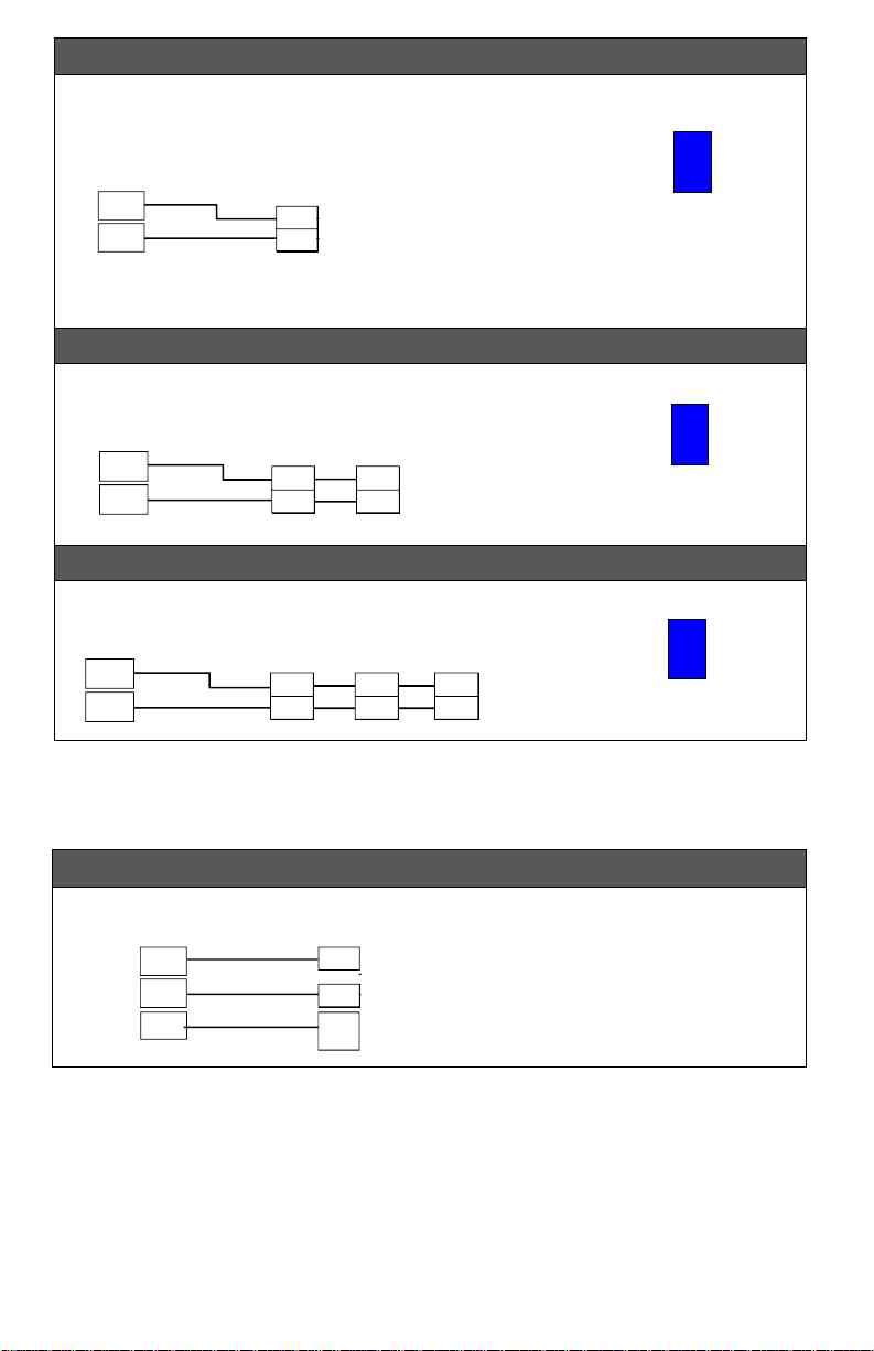
Wiring example of single remote room sensor:
1
2
ON
Dip switch
setting for:
1 sensor
S2-1 = ON
S2
1
2
ON
Dip switch
setting for:
2 sensors
S2-1 = OFF
S2
1
2
ON
Dip switch
setting for:
3 sensors
S2-1 = OFF
S3010W1000
Remote wiring 1 sensor
S2=On,
S3=On
VZ7260 Series
Controller
RS
Scom
Scom
RS
Scom
RS
2 x S3010W1000
Remote wiring 2 sensors
S2=On,
S3=Off
Scom
RS
Scom
RS
VZ7260 Series
Controller
RS
Scom
Scom
RS
Scom
RS
3x S3010W1000
Remote wiring 3 sensors
S2=Off,
S3=Off
Scom
RS
Scom
RS
Scom
RS
Scom
RS
VZ7260
Series
Controller
RS
Scom
Scom
RS
Scom
RS
Co2 Sensor
VZ7260 Series
Controller
24VAC
Com
Com
RS 24VAC
AI4
0-10
VDC
Wiring examples of 2 remote room sensors for averaging applicat ions:
Wiring examples of 3 remote room sensors for averaging applicat ions:
-2 = ON
-2 = ON
CO2 sensor wiring
Wiring example of C O 2 sensor:
12 | VZ7260W Series- Installation Guide
Page 13

CONFIGURING AND STATUS DISPLAY INSTRUCTIONS
Stand-By
Unoccup
Status disp lay
The Terminal Eq uipme nt Cont rol ler features a t wo-l ine, ei ght-character di splay. There i s a
low backlight level that is always act ive and can only be seen at night.
When left unattended, the Terminal Equipment Controller has an auto scrolling display
that shows the current status of the system.
Each item is sc rolled sequentially with the bac k light in low level mode. Press ing any key
will cause the back light to come on to high level.
Manual scrolling of each menu item is achieved by pressing the Yes (scroll) key
repetitively. The last item viewed will be shown on the display for 30 seconds before
returning to automat ic scrolling. Temperature is automatically updated when scr olling is
held.
Sequence of auto-scroll status display:
ROOM
TEMPERATURE
RoomTemp
x.x °C or°F
OCCUPANCY
STATUS
Occupied
OUTDOOR
TEMPERATURE
Outdoor
x.x °C or°F
Override
Outdoor air temperature
Outdoor air temperature display is only enabled when outdoor air temperature sensor is
connected.
• A maximum range status display of 50 °C ( 122 °F ) indicates a shorted sensor.
Associated functions, such as mode lock outs and economizer func tion are
automatically di sabled.
• A minimum range status -40 °C ( -40 °F ) is not displayed and indicates a opened
sensor or a sensor not connected. Associ ated functions, such as m ode lockouts and
economizer func tion are automatically disabled.
Occupancy Status
• Oc cupied, Stand-By, Unoccupied and Override status are displayed on the scrolling
display.
• Two s tatus LED’s on the controller cover are used t o indicate a call for heat or a call
for cooling
When heating & reheat is ON, the HEAT LED will illuminate
When cooling is O N, the COOL LED will illumi nate
13 | VZ7260W Series- Installation Guide
Page 14

USER INTERFACE
An Override can be made during an Unoccupied per iod. If the Override
“ToccTime.”
Adjust the setpoints down;
Local Zone Mode as Dictated by Attached Master RTU Controller
RTU in cooling mode with Local Reheat enabled
current displayed one and the other.
Cool XX.X °F or °C and Heat XX.X °F or °C
simultaneously
User configuration menu
• Unoccupied mode Override
An Override can be made during an unoccupied
period. If the Over ride option is enabled in the
lockout configuration pressing the Over ride button
will resume occupied setpoints for a time specified
by the parameter; “ToccTime.”
• Keypad interface
Override
Down
option is enabled i n the lockout configurat ion pressing the overri de key will
resume occupied setpoints for a time specified by the parameter;
In cooling mode only the cooling setpoint displayed.
In heating mode onl y the heating setpoint displayed.
In auto mode; (See below).
Adjust the setpoints up;
Up
In cooling mode onl y the cooling setpoint displayed.
In heating mode onl y the heating setpoint displayed.
In auto mode; (See below).
1. Any setpoint change can be perm a n ent or temporary based on configura ti o n param e te r (Setpoint Type).
2. Any setpoint written through the network will be permanent and cancel any active temporary setpoints.
3. Lockouts to access certain functions are made with configuration parameter (lockout).
4. If in Unoccupied period, pressing the Down button will display the following message on the display: “Press
Override First”.
Occupied setpoint adjustments
• Setpoint presented to user is the setpoint from t he
last action tak en by the controller or the one
RTU in
cooling
mode
RTU In
heating
mode
currently in use.
• Both heating and cooling setpoints are changed
simultaneously while respecting the minimum
configured deadband.
• If the other setpoint is t he one desired, then the
OVERRIDE button is used to toggle between the
Cool XX.X
°F or °C
Heat XX.X
°F or °C
Both heating & cooling setpoints are changed
Unoccupied and Stand-By setpoints adjustments
Setting the Unoccupied and Stand-By setpoints is done through the net w ork or through
configuration s etup only.
When in Unoccupied period, pressing the up or down button will display the following
message on the display: “Press Override Fi rst”.
14 | VZ7260W Series- Installation Guide
Page 15

Local keypad interface
An Override can be made during an unoccupied period. If the Override
ToccTime
In cooling mode only the cooling setpoint is displayed,
In auto mode, (See below )
In cooling mode only t he cooling setpoint i s displayed,
In auto mode, (See below)
option is enabled i n the lockout configurat ion pressing the overri de key
will resume occupied setpoints for a time specified by parameter
In heating mode only the heating setpoint is displayed
In heating mode only the heating setpoint is displayed
When left unattended for 45 seconds, the display will resume automatic status
display scroll ing.
To turn on the back light, press any key on the fr ont panel. The back lit display will
turn off automati cally after 45 seconds.
INSTALLER CONFIGURATION PARAMETER MENU
Configuration can be done through the network or locally at the Termi nal Equipment
Controller.
To enter configuration, press and hold the mi ddle button (°C/°F or O verride) for
8 seconds.
• If a password lockout is active, “Password” is prompted. Enter pass w ord value
using the “up” and “down” arrows and press the middle button again to gain
access to all configuration properties of the Terminal Equipment Controller.
Entering a wrong password will prevent local access to the configur ation menu.
Press the same middle button repetit ively to scroll between all the available
parameters.
Use the up and down key to change the parameter to the desired value.
To acknowledge and save the new value, press the middle button again.
The next parameter w ill now be displayed.
15 | VZ7260W Series- Installation Guide
Page 16

Configuration Parameters
Range is: 0 to 1000
Zone MAC
RTC MAC address must be unique for the entir e
127.
PAN ID
This parameter (P ersonal Area Network I dentification) is
Default Value
Significance and Adjustments
PswrdSet
Configuration parameters
menu access password
Default value = 0
No password prompted
Zone Controller Controller
network address
Default Value: 255
Personal Area Networ k
Identification
Default value = 0
Range is: 0 to 500
This parameter s ets a password access to prevent
unauthorized access to the configurati on m enu
parameters. A default value of “0” will not prompt a
password or lock the access to the configurat ion
menu.
network.
1 to 255 (Increment s: 1 or 10)
For BACnet™ models valid range to use is from 1 to
used to link specific controllers to a single specific
Viconics wireless gateway ( VWG / Jace-Driver ) or a
specific VZ76 RTU controller. For every controller
reporting to a VW G / Jace-Driver or VZ76 controller, be
sure you set the SAME PAN ID value.
The default value of 0 is NOT a valid PAN ID. The valid
range of available PAN ID is from 1 to 500
16 | VZ7260W Series- Installation Guide
Page 17

When PAN ID is used with a range of 251 to 500, for (SA) Stand-Alone System s
In this applic ation, the VZ76 controller(s) are the coordinators to their own system. I.E.
they are the network masters for each VZ72 controller reporting to them.
• Wireless controller factory default Channel & PAN ID = Controller( s) offline
• VZ76 RTU controller is the network coordinator.
• Range of PAN ID on all controllers to use 251 to 500. This r ange is reserved for
stand-alone syst em operation.
Examples:
Notes:
Each system with a VZ76 RTU master will use a uni que P AN ID and / or Channel settings.
17 | VZ7260W Series- Installation Guide
Page 18

When PAN ID is used with a range of 1 to 250, for (NS) Networked System s
In this applic ation, any controller( s) are simply router to t he system. The VWG / Jace-
Driver is the coordinators to the system. I.E. the VWG / Jace-Driver is the network
masters for ANY controller(s) reporting to them.
• Wireless controller factory default Channel & PAN ID = Controller( s) offline
• VWG Jace -Driver is the network coordinator
• Any controllers ( VZ72’s, VZ76xx RTU’s or any VT7xxx wireless controllers ) act
as routers.
• Range of PAN ID on all controllers to use 1 to 250. Reserved for networked
system operation.
Examples:
Notes:
• Each controller(s) to use same PAN ID and Channel as VWG Jace-Driver
coordinator.
• VWG / Jace-Driver supports network integr ation for required GUI / System /
Status objects.
18 | VZ7260W Series- Installation Guide
Page 19

Channel
Conditional parameter to Wireless models
ZoneBaud
Conditional parameter to BACnet MS-TP models
Channel selection
Default value = 10
(VZ7260CX5x00W) o nly
This parameter wi ll only appear when a wireless network
adapter is present. If the thermostat is installed with a
BACnet adapter, this parameter will not be used or
displayed
This parameter (C hannel) is used to link specific
thermostats to specific Viconics wir eless gateway(s)
( VWG / Jace-Driver) or main VZ76 RTU t hermostat. For
any system, be sur e you set the SAME channel value
both at the network coordinator and all the VZ 72
thermostat(s).
Viconics recommends using only the f ollowing
channels: 15, 25 & 26
The default value of 10 is NOT a valid channel. The valid
range of available c hannel is from 11 to 26
Range is: 10 to 26
Zone Thermostat
Communication Baud Rate
Default Value: 4 = Auto
(VZ7260CX5x00B) o nly
This parameter wi ll set the network’s baud r ate.
0 = 9600 KBps
1 = 19200 KBps
2 = 38400 KBps
3 = 76800 KBps
4 = Auto Bauding ( Baud Rat e will match detected Baud
Rate
19 | VZ7260W Series- Installation Guide
Page 20

Get From
Controller Get From another
Entering a new MAC address enabled an automat ic
RTC MAC
Master VZ76 RTU sys tem controller to which current
Removes the scrolling display and only presents the
Off = Scroll not act ive
°F for Fahrenheit scale
device configurat ion utility
Default value = 255
Range is: 1 to 255
routine that automat ically fetches al l the required
configuration pr operty of the current devi ce from another
one already configured to the same required property
values. If another value than the default value of 255 is
entered, user will then be prompted to exit the
Configuration Menu.
Ex.: If you are currently configuring MAC12 and the
settings exactly match the settings of ZN MAC5, then
enter 5 as the current parameter value.
If the process is successful and all required configuration
properties have been copied, the value will revert back to
255.
If the process is NOT successful and all required
configuration pr operties have NOT been copied ( either
the reference device is NOT the same model number or
is offline or does not exists ) the value will revert back to
254 to indicate the failure of the process.
Leaving the Get From parameter to 255 means that
every configurati on parameters has to be set manually.
RTC Controller network
address
Default: 4
MenuScro
Menu scroll
Default: On = Scr oll active
C or F
Sets the display scale of the
controller
Default: °F
VZ72 Zone controller is attached
1 to 127 (Increment s: 1 or 10)
room temperature t o the user.
With this option enabled, no status is given for
occupancy and outdo or temperature.
On = Scroll active
°C for Celsius sc ale
20 | VZ7260W Series- Installation Guide
Page 21

Lockout Keypad lockout
0
1
2
3
BI1
(None): No functi on w ill be associated wit h the input. Point
AI4
(None): No function will be associated wi th the input. Point
levels
Default value = 0 No lock
0 = No lock
1 = Low level
2 = Medium level
3 = High level
USER KEY FUNCTIONS
LEVEL
Binary input no.1 configuration
Default: None
Occupied temperatu re
setpoints
Local override only
can still be monit ored through the BACnet™ network.
(Motion NO): Used in Occupied Mode only to toggle from
the Occupied setpoints to the Stand-By setpoints when no
motion is detected for 60 minutes at the zone.
When motion is detected at the zone, the Occupied setpoint
resumes.
Contact opened = No motion detected.
Contact closed = M otion detected.
(Motion NC): Used in Occupied Mode only to toggle fr om
the Occupied setpoints to the Stand-By setpoints when no
motion is detected for 60 minutes at the zone.
When motion is detected at the zone, the Occupied setpoint
resumes.
Contact opened = Moti on detected.
Contact closed = N o m otion detected.
Global override
access
Analog input no.4 configuration
Default: None
can still be monit ored through the BACnet net w ork.
CO2: Used when a 0-10VDC CO2 sensor is connected to
AI4 input. The value of the input signal is displayed in AI4
Dis parameter.
21 | VZ7260W Series- Installation Guide
Page 22

RehtConf
Number of Reheat Stages and
0 = None
1 = Modulating Duct Reheat Only
2 = On-Off Duct Reheat Only
Off reheat output for a local
RTU in heating mode with reheat uses Control Curve 6
3 = On-Off Perimeter Reheat Only
Off reheat output for a local
RTU in heating mode uses Control Curve 6
4 = Modulating Duct Reheat & On-Off Perimeter Reheat
The first reheat stage will use the modulating reheat output for a
RTU in heating mode uses Control Curve 10
their applications
Default: 1 = Modulating Duct
Reheat Only
Zone will operate in VAV heating or cooling only based on the
Master RTU mode without any reheat.
RTU in cooling mode uses Control Curve 1
Zone will operate in VAV heating or cooling based on the
Master RTU mode and uses the Modulating reheat output for a
local Modulating duct reheat device like a proportional hot water
valve or an SCR. The local reheat can be enabled or disabled
based on the outdoor air temperature and AO2 OALK.
RTU in cooling mode uses Control Curve 3
Zone will operate in VAV heating or cooling based on the
Master RTU mode and uses the OnOn-Off duct reheat device like a 2 position hot water valve or a
single electric duct heater. The local reheat can be enabled or
disabled based on the outdoor air temperature and BO5 OALK.
RTU in cooling mode with On-Off Reheat (BO5 Time=0=15
minutes) uses Control Curve 5b
RTU in cooling mode with On-Off Pulsed Reheat (BO5
Time=1=10 seconds) uses Control Curve 5a
Zone will operate in VAV heating or cooling based on the
Master RTU mode and uses the OnOn-Off perimeter reheat device like a 2 position hot water valve
or a electric baseboard unit. The local reheat can be enabled or
disabled based on the outdoor air temperature and BO5 OALK.
RTU in cooling mode uses Control Curve 7
Zone will operate in VAV heating or cooling based on the
Master RTU mode and uses 2 stages of local reheat.
local modulating duct reheat device like a proportional hot water
valve or an SCR. The local reheat stage can be enabled or
disabled based on the outdoor air temperature and AO2 OALK.
The second reheat stage will use the On-Off reheat output for a
local On-Off perimeter reheat device like a 2 position hot water
valve or a electric baseboard unit. The local reheat stage can
be enabled or disabled based on the outdoor air temperature
and BO5 OALK
RTU in cooling mode uses Control Curve 9
22 | VZ7260W Series- Installation Guide
Page 23

5 = Duct heater & On-Off/Pulsed perimeter r eheat (All
electric)
OALK
Zone will operate in VAV heating or cooling based on the
Master RTU mode and use 2 stages of local reheat .
The first reheat s tage will use the modulating BO5 reheat
output (10s or 15m c ycles) for a local modulat ing electric
duct reheat device with a 24 Vac fired SSR. The local reheat
stage can be enabled or disabled based on the outdoor air
temperature and BO5 OALK
The second reheat s tage will use the reheat out put BO3
(15m cycles) and/or BO4 (10s cycles) for a local OnOff/Pulsed perimeter reheat device like a 2 position electri c
baseboard unit. The local reheat stage can be enabled or
disabled based on the outdoor air temperature and FO2
23 | VZ7260W Series- Installation Guide
Page 24

AO2RA/DA
AO2 OAL K
Outdoor air temperature value from the RTU controller under
VZ7260F5x00B models only
FO2 OALK
Outdoor air temperature value from the RTU controller under
BO5 OAL K
Outdoor air temperature value from the RTU controller under
(Increments : 5° or 50°)
RA/DA
Reverse acting or D irect acting
actuator signal for Reheat 1
Analog output signals
Default: DA signal
Changes the action of the reheat 1 analog output .
Valid only if analo g reheat sequences are enabled
DA = Direct acting
0 to 100 % = 0 to 10 VDC
RA = Reverse acting
0 to 100 % - 10 to 0 VDC
VZ7260F5x00B models only
Zone’s analog reheat (AO2)
outside air temperature lockout
Default: 55°F (13 °C )
FL TM Dp
Floating damper actuator
timing – Output BO1-BO2
Default: 1.5 min utes
FL TM Rh
Floating damper actuator
timing – Output BO3-BO4
Default: 1.5 min utes
Zone’s BO3-BO4 reheat
floating output outside air
temperature lockout
Default: 55°F (13 °C )
which the analog reheat stage will be allow ed to be used.
Function will onl y be enabled if a valid outside air
temperature value is received at the zone.
-40 to 122 °F (-40.0 to 50.0 °C )
(Increments : 5° or 50°)
Maximum stroke time of floating damper actuator
Output BO1-BO2.
0.5 to 9.0 in 0.5 minutes increment
VZ7260C5x00B models only
Maximum stroke time of floating damper actuator
Output BO3-BO4.
0.5 to 9.0 in 0.5 minutes increment
VZ7260C5x00B models only
which the BO3-BO4 rehe at output stage will be allowed to
be used
Function will onl y be enabled if a valid outside air
temperature value is received at the zone.
-40 to 122 °F (-40.0 to 50.0 °C ) (Increments: 5° or 50°)
VZ7260C5x00B models only
Zone’s On-Off reheat (BO5)
outside air temperature lockout
Default: 32°F (0°C)
which the On-Off reheat stage will be allowed to be used.
Function will onl y be enabled if a valid outside air
temperature value is received at the zone.
-40 to 122 °F (- 40.0 to 50. 0 °C )
24 | VZ7260W Series- Installation Guide
Page 25

BO5 Time
Default: 0 = 15 minute
BO5 cont
Contact Closed
Time delay between t he m oment when the PIR cover
Time delay between t he m oment where the controller
Range is: 0.0 to 24.0 hours in 0.5hr incr em ents.
Default: 80 °F (27°)
Sets the time base for the ONOff reheat output i f used
Valid only if reheat sequences are enabled wi th BO5
0= 15 minutes
1= 10 seconds for Sol id state relays
BO5 contact func tion
Default value = 0 = NO
St-By TM
Stand-by Timer value
Default 0.5 hours
Unocc TM
Unoccupied Timer val ue
Default 0.0 hours
Unocc HT
Unoccupied heating setpoint
Default: 62 °F (17°C)
Enables the use of normally opened or normally closed 2
position reheat valves.
0 = NO, Energized = Contact Closed / De-energized =
Contact Opened
1 = NC, Energized = Contact Opened / De-energized =
detected the last movement in the area and the time when
the controller’s stand-by mode and setpoi nts become active.
Range is: 0.5 to 24.0 hours in 0.5hr incr em ents.
toggles to stand-by m ode and the time which t he controller
unoccupied mode and setpoints become active.
The factory value or 0.0 hours: Setting this parameter to its
default value of 0.0 hours disables the unoccupied timer.
This prevents the controller to drif t from stand-by mode to
unoccupied mode when PIR functions are used.
Unoccupied heating setpoint adjustment.
Heating setpoint r ange is:
40 to 90 °F (4.5 to 32.0 °C)
(Increments :0.5° or 5°)
Unocc CL
Unoccupied cooling setpoint
limit
Unoccupied cooling setpoint adjustment.
Cooling setpoint r ange is:
54 to 100 °F (12.0 to 37. 5 °C ) (Increments: . 5° or 5°)
25 | VZ7260W Series- Installation Guide
Page 26

St-By HT
St-By CL
saved to permanent memory.
Cal RS
Deadband
(1.0 to 2.5 °C, 0.5 °C increments)
Stand-by heating s etpoint
Default: 65 °F (18°C)
Stand-by cooling s etpoint limit
Default: 75 °F (24°C)
Stand-by heating s etpoint adjustment. This setpoint will be
used if there is a motion detector connect ed and configured
on BI1 or a PIR sensor cover used.
Heating setpoint r ange is:
40 to 90 °F (4.5 to 32.0 °C)
Stand-by cooling s etpoint adjustment. This setpoint will be
used if there is a motion detector connect ed and configured
on BI1 or a PIR sensor cover used.
Cooling setpoint r ange is:
54 to 100 °F (12.0 to 37. 5 °C )
Set Type
Temporary user setpoints
enable
Default: permnent
TOccTime
Temporary occupancy time
Default value = 2 hours
Room air temperatur e sensor
calibration
Default: 0.0 °F or °C
Minimum deadband
Default: 2.0 °F (1.0 °C)
Enables temporar y setpoints feature t o any local change of
occupied setpoints.
temporar: (t em porary) Any new setpoints entered by the
user will revert back to their default value after internal timer
ToccTime expires.
To change setpoints permanently, revert to No this variable
or write new setpoint values through the net w ork. Any
setpoints writ ten through the network w ill be permanent ones
and saved to permanent m emory.
permnent: (permanent) Any changes of occ upied setpoints
entered by the user through the keypad are perm anent and
Temporary occupancy time with occupied m ode setpoints
when override function is enabled.
When the controller is in unoccupi ed m ode, function is
enabled with the local override keypad button.
Range is: 0,1, 2, 3, 4 & up to 12 hours
(Increments : 1 hr or 10 hr)
Offset that can be added or subtracted to actual displayed
and used room temperature
± 5.0 °F, 1.0 °F increments
(± 2.5 °C, 0.5 °C increments)
Minimum deadband value between the heating and cooling
setpoints. If m odified, it will be first applied only when a
setpoint is modified.
2, 3, 4 or 5 °F, 1.0 °F increments
26 | VZ7260W Series- Installation Guide
Page 27

Pband
Value
F scale
C scale
3
3 F
1.7 C 4 4 F
2.2 C 5 5 F
2.8 C 6 6 F
3.3 C 7 7 F
3.9 C 8 8 F
4.4 C 9 9 F
5.0 C
10
10 F
5.6 C
Heat max
Default: 90 °F (32 °C)
Cool min
DisMinPo
Proportionnal band setting
Default is : 3
Adjust the proportional band used by the controller PI
control loop.
Warning. Note that t he default value of 3.0 °F (1. 2 °C )
gives satisfactory operation in most normal installation
cases. The use of a s uperior proportional ba nd different
than the factory one i s normally warranted in applications
where the controller location is probl em atic and leads to
unwanted cycling of the unit. A typical example is a wall
mounted unit where the controller is installed between the
return and supply air feeds and is directly influenced by
the supply air st ream of the unit.
Maximum local heati ng
setpoint limi t
Minimum local cooling
setpoint limi t
Default: 54 °F (12 °C)
Enable / Disable damper
minimum position
Default : On
27 | VZ7260W Series- Installation Guide
Maximum local occupied heating user setpoints
adjustments.
Heating setpoint r ange is:
40 to 90 °F (4.5 to 32.0 °C) (Increments: 0.5° or 5°)
Minimum local occupied cooling user s etpoints
adjustments.
Cooling setpoint r ange is:
54 to 100 °F (12.0 to 37. 5 °C ) (Increments: 0.5° or 5°)
Enables or disabled the damper minimum position
(parameter Min PO) if the controller cooling or heating
demand is not the s am e as the zone sequence. Example:
if controller c all s for heating and the zone sequence is
Cool (sent by the VZ7 6xx master controller).
On = Enable Minimum Position
Off = Disable Minimum P osition
Page 28

Min Pos
Zone damper minimum
Max Pos
Sets the maximum position of the damper for both heating
MaxHTPos
Opens the damper up to t his maximum position when the
0 to 100% (Increments: 1% or 10%)
PIHT Wei
Weight of the zone in the calculation of the PI Heating
PICL Wei
Calculation of t he R TU controller.
Not a configurati on parameter. Only dis plays the
hours. These
position
Default : 10%
Sets the minimum position of the damper.
0 to 100% (Increments: 1% or 10%)
Zone damper maximum
position
Default : 100%
Zone damper Maximum
heating positi on
Default : 30%
PI heating weight zone output
used for RTU controller
demand calculations
Default value: 100%
and cooling mode of the RT U .
0 to 100% (Increments: 1% or 10%)
primary air is col d and used only when the RTU is in
cooling mode and there is a local call for reheat using the
reheat output(s).
This will maximizes the efficiency and del ivery of a duct
mounted reheat device by augmenting the airflow on a
single duct VAV.
Demand calculat ion of the RTU controller.
If a zone has a special application (servers room,
mechanical room, etc) and have impact on ot her rooms’
comfort, this parameter can be set to 0%.
Please refer to the Zoning System Application Guide for
more information that impacts systems operation.
Set all heating weig ht to 0% if the RTU is cooling only.
Valid range: 0%, 25%, 50%, 75% and 100%
PI cooling weight zone output
used for RTU controller
demand calculations
Default value: 100%
If a zone has a special application (servers room,
mechanical room, etc) and have impact on ot her rooms’
comfort, this par ameter can be set to 0%.
Please refer to the Zoning System Application Guide for
more information that impacts systems operation.
HT Perfo
Controller’s heating
performance
Valid range: 0%, 25%, 50%, 75% and 100%
controller’ s performance in heating mod e.
This value is only val id if there’s no change in system
mode, setpoints or occupancy for at least 1.5
changes cause the value to reset to an invali d value
Default value: None
28 | VZ7260W Series- Installation Guide
(above 20°F)
Page 29

CL Perfo
Not a configurati on parameter. Only dis plays the
Room CO2
object)
AI4 Value
object)
YES (Only in
Occupied mode)
Controller’s cooling
performance
Default value: None
controller’ s performance in cooling mod e.
This value is only val id if there’s no change c hange in
system mode, setpoints or occupancy for at least 1.5
hours. These chang es cause the value to reset to an
invalid value (abo ve 20°F)
UI3 Dis
UI3 display value
CO2
Room CO2 value
Used as diagnostic / service help to troubleshoot and
diagnose sensor operation
Supply or Disc harge temperature
Used as diagnostic / service help to troubleshoot and
diagnose sensor operation. This value is displayed only if
AI4 parameter is set to CO2.
0 to 2000 ppm
AI4 INPUT FOR CO2 SENSOR
The VZ7260X5x00B s eries features a 0-10VDC CO2 s ensor input which value can be used
by the VZ7656E1000B controller for Indoor Air Quality (AIQ) control.
Here’s the table showing the CO2 value treatm ent based on the AI4 paramet er setting:
AI4
parameter
setting
CO2 display
at the
controller
Value Written to
VZ7656E1000B
Value available
in ppm (BACnet
available in
VDC (BACnet
None NO NO NO YES
CO2 YES
29 | VZ7260W Series- Installation Guide
YES YES
Page 30

REFERENCED OPERATIONAL CONTROL CURVES
Temperature increase
Device opened
10 Vdc or Max Pos
AO1
RTC in Heating mode
RehtConf = 0 (No reheat at the zone
CC2
Device closed
Cooling
Setpoint
DEAD BAND
Heating
Setpoint
AO2 = 0 Vdc & BO5 = Off
Min Pos
if DisMinPo = Enabled
or
0 Vdc
if DisMinPo = Disabled
Temperature increase
Deviceopened
10 Vdc or Max Pos
Deviceclosed
Min Pos
if DisMinPo = Enabled
AO1
Cooling
Setpoint
RTC in Cooling mode
RehtConf = 0 (No reheat at the zone)
CC1
DEAD BAND
Heating
Setpoint
AO2 = 0 Vdc & BO5 = Off
or
0 Vdc
if DisMinPo = Disabled
Temperature increase
Deviceopened
100% or Max Pos
Deviceclosed
Min Pos
if DisMinPo = Enabled
BO1-BO2
Cooling
Setpoint
RTC in Cooling mode
RehtConf = 0 (No reheat at the zone)
CC1
DEAD BAND
Heating
Setpoint
BO3-BO4 = 0% & BO5 = Off
or
0%
if DisMinPo = Disabled
Temperature increase
Device opened
100% or Max Pos
BO1-BO2
RTC in Heating mode
RehtConf = 0 (No reheat at the zone)
CC2
Device closed
Cooling
Setpoint
DEAD BAND
Heating
Setpoint
BO3-BO4 = 0% & BO5 = Off
Min Pos
if DisMinPo = Enabled
or
0%
if DisMinPo = Disabled
RehtConf = 0 = None
VZ7260F Series: Analog Outputs
VZ7260C Series: Floating Out puts
30 | VZ7260W Series- Installation Guide
Page 31

RehtConf = 1 = Analog Duct Reheat Only
Temperature increase
Cooling
Setpoint
RTC in cooling mode
RehtConf = 1 (Analog Duct Reht Only)
BO5 = Off
(1) If AO2 stage is locked, AO1 = Min Pos
(2) If AO2 stage is locked, AO1 = 0Vdc
DEAD BAND
Heating
Setpoint
Device closed
0%
Device opened
100%
CC3
Device closed
Min Pos
AO1
Device opened
MaxHeat Pos (1)
AO2
Deviceopened
10 Vdc or Max Pos
0Vdc
if DisMinPo = Disabled (2)
Temperature increase
AO1
Device
opened 100%
Device
closed 0%
AO2
CC4
Cooling
Setpoint
DEAD BAND
Heating
Setpoint
RTC in Heating mode
RehtConf = 1 (Analog Duct Reht Only)
BO5 = Off
Device opened
10 Vdc or Max Pos
Device closed
Min Pos
if DisMinPo = Enabled
or
0 Vdc
if DisMinPo = Disabled
Temperature increase
Cooling
Setpoint
RTC in cooling mode
RehtConf = 1 (Analog Duct Reht Only)
BO5 = Off
(1) If BO3-BO4 stage is locked, BO1-BO2 = Min Pos
(2) If BO3-BO4 stage is locked, BO1-BO2 = 0%
DEAD BAND
Heating
Setpoint
Device closed
0%
Device opened
100%
CC3
Device closed
Min Pos
BO1-BO2
Device opened
MaxHeat Pos (1)
BO3-BO4
Deviceopened
100% or Max Pos
0%
if DisMinPo = Disabled (2)
Temperature increase
BO1-BO2
Device
opened 100%
Device
closed 0%
BO3-BO4
CC4
Cooling
Setpoint
DEAD BAND
Heating
Setpoint
RTC in Heating mode
RehtConf = 1 (Floating Duct Reht Only)
BO5 = Off
Device
opened
100% or Max Pos
Device closed
Min Pos
if DisMinPo = Enabled
or
0%
if DisMinPo = Disabled
VZ7260F Series: Analog Outputs
VZ7260C Series: Floating Out puts
31 | VZ7260W Series- Installation Guide
Page 32

RehtConf = 2 = On-Off Duct Reheat O nly
RTC in Cooling mode
RehtConf = 2 ( On/Off Duct Reht Only)
AO2 = 0%
On/Off Rht Time Base = 10 sec
(1) If BO5 stage is locked, AO1 = Min Pos
When BO5 = 0%, AO1 = Min Pos
When BO5 = 100%, AO1 = Max Pos
Otherwise, AO1 output is proportional to BO5 output
Temperature increase
Cooling
Setpoint
DEAD BAND
Heating
Setpoint
Device closed
0%
Device opened
100%
CC5a
Device closed
Min Pos
AO1
Device opened
MaxHeat Pos (1)
BO5
Device opened
10 Vdc or Max Pos
0Vdc
if DisMinPo = Disabled (2)
(2) If BO5 stage is locked, AO1 = 0Vdc
When BO5 = 0%, AO1 = 0 Vdc
When BO5 = 100%, AO1 = Max Pos
Otherwise, AO1 output is proportional to BO5 output
RTC in Cooling mode
RehtConf = 2 ( On/Off Duct Reht Only)
AO2 = 0%
On/Off Rht Time Base = 15 min
(1) If BO5 stage is locked, AO1 = Min Pos
When BO5 = Off, AO1 = Min Pos
When BO5 = On, AO1 = Max Pos
Temperature increase
Cooling
Setpoint
DEAD BAND
Heating
Setpoint
Device Off
Device On
CC5b
Device closed
Min Pos
AO1
Device opened
MaxHeat Pos (1)
BO5
Device opened
10 Vdc or Max Pos
BO5 Output Off
BO5 Output On
Device closed
Min Pos
if DisMinPo = Enabled
or
0 Vdc
if DisMinPo = Disabled (2)
(2) If BO5 stage is locked, AO1 = 0Vdc
When BO5 = Off, AO1 = 0Vdc
When BO5 = On, AO1 = Max Pos
Temperature increase
AO1
Device
On
Device
Off
BO5
CC6
Cooling
Setpoint
DEAD BAND
Heating
Setpoint
RTC in Heating mode
RehtConf = 2 (On/Off Duct Reht Only)
AO2 = Off
Device opened
10 Vdc or Max Pos
Device closed
Min Pos
if DisMinPo = Enabled
or
0 Vdc
if DisMinPo = Disabled
VZ7260F Series: Analog Outputs
10
32 | VZ7260W Series- Installation Guide
Page 33

VZ7260C Series: Floating Out puts
RTC in Cooling mode
RehtConf = 2 ( On/Off Duct Reht Only)
BO3-BO4 = 0%
On/Off Rht Time Base = 10 sec
(1) If BO5 stage is locked, BO1-BO2 = Min Pos
When BO5 = 0%, BO1-BO2 = Min Pos
When BO5 = 100%, BO1-BO2 = Max Pos
Otherwise, BO1-BO2 output is proportional to BO5 output
Temperature increase
Cooling
Setpoint
DEAD BAND
Heating
Setpoint
Device closed
0%
Device opened
100%
CC5a
Device closed
Min Pos
BO1-BO2
Device opened
MaxHeat Pos (1)
BO5
Device opened
100% or Max Pos
0%
if DisMinPo = Disabled (2)
(2) If BO5 stage is locked, BO1-BO2 = 0%
When BO5 = 0%, BO1-BO2 = 0%
When BO5 = 100%, BO1-BO2 = Max Pos
Otherwise, BO1-BO2 output is proportional to BO5 output
RTC in Cooling mode
RehtConf = 2 ( On/Off Duct Reht Only)
BO3-BO4 = 0%
On/Off Rht Time Base = 15 min
(1) If BO5 stage is locked, BO1-BO2 = Min Pos
When BO5 = Off, BO1-BO2 = Min Pos
When BO5 = On, BO1-BO2 = Max Pos
Temperature increase
Cooling
Setpoint
DEAD BAND
Heating
Setpoint
Device Off
Device On
CC5b
Device closed
Min Pos
BO1-BO2
Device opened
MaxHeat Pos (1)
BO5
Device opened
100% or Max Pos
BO5 Output Off
BO5 Output On
Device closed
Min Pos
if DisMinPo = Enabled
or
0%
if DisMinPo = Disabled (2)
(2) If BO5 stage is locked, BO1-BO2 = 0%
When BO5 = Off, BO1-BO2 = 0%
When BO5 = On, BO1-BO2 = Max Pos
Temperature increase
BO1-BO2
Device
On
Device
Off
BO5
CC6
Cooling
Setpoint
DEAD BAND
Heating
Setpoint
RTC in Heating mode
RehtConf = 2 (On/Off Duct Reht Only)
BO3-BO4 = Off
Device opened
100% or Max Pos
Device closed
Min Pos
if DisMinPo = Enabled
or
0%
if DisMinPo = Disabled
33 | VZ7260W Series- Installation Guide
Page 34

RehtConf = 3 = On-Off Perimeter Reheat Only
Temperature increase
AO1
Device
On
Device
Off
BO5
CC6
Cooling
Setpoint
DEAD BAND
Heating
Setpoint
RTC in Heating mode
RehtConf = 2 (On/Off Duct Reht Only)
AO2 = Off
Device
opened
10 Vdc or Max Pos
Device closed
Min Pos
if DisMinPo = Enabled
or
0 Vdc
if DisMinPo = Disabled
Temperature increase
Device closed
Min Pos
AO1
Cooling
Setpoint
RTC in cooling mode
RehtConf = 3 ( On/Off Peri Rht Only)
AO2 = 0%
CC7
DEAD BAND
Heating
Setpoint
Device Off
Device On
BO5
AO1
Device opened
10 Vdc or Max Pos
AO1 = 0Vdc
if DisMinPo = Disabled
Temperature increase
BO1-BO2
Device
On
Device
Off
BO5
CC6
Cooling
Setpoint
DEAD BAND
Heating
Setpoint
RTC in Heating mode
RehtConf = 2 (On/Off Duct Reht Only)
BO3-BO4 = Off
Device opened
100% or Max Pos
Device closed
Min Pos
if DisMinPo = Enabled
or
0%
if DisMinPo = Disabled
Temperature increase
Device closed
Min Pos
BO1-BO2
Cooling
Setpoint
RTC in cooling mode
RehtConf = 3 ( On/Off Peri Rht Only)
BO3-BO4 = 0%
CC7
DEAD BAND
Heating
Setpoint
Device Off
Device On
BO5
BO1
-
BO2
Device opened
100% or Max Pos
BO1-BO2 = 0%
if DisMinPo = Disabled
VZ7260F Series: Analog Outputs
VZ7260C Series: Fl oating Outputs
34 | VZ7260W Series- Installation Guide
Page 35

RehtConf = 4 = Analog Duct Reheat & On-Off Perimeter Reheat
Temperature increase
Deviceclosed
Min Pos
Cooling
Setpoint
RTC in cooling mode
RehtConf = 4 (Terminal reheat on AO2 &
Perimeter Heating on BO5)
(1) If AO2 stage is locked, AO1 = Min Pos
(2) If AO2 stage is locked, AO1 = 0Vdc
CC9
DEAD BAND
Heating
Setpoint
Device opened
Max Heat Pos (1)
AO2
Device closed
0%
Device
On
Device
Off
BO5
Device opened
100%
AO1
Device opened
10 Vdc or Max Pos
0Vdc
if DisMinPo = Disabled (2)
Temperature increase
AO1
Device
Opened 100%
Device
Closed 0%
AO2
CC10
Cooling
Setpoint
DEAD BAND
Heating
Setpoint
RTC in Heating mode
RehtConf = 4 (Terminal reheat on AO2 &
Perimeter Heating on BO5)
Device
opened
10 Vdc or Max Pos
Device
On
BO5
Device
Off
Device closed
Min Pos
if DisMinPo = Enabled
or
0 Vdc
if DisMinPo = Disabled
Temperature increase
Deviceclosed
Min Pos
Cooling
Setpoint
RTC in cooling mode
RehtConf = 4 (Terminal reheat on BO3-BO4 &
Perimeter Heating on BO5)
(1) If BO3-BO4 stage is locked, BO1-BO2 = Min Pos
(2) If BO3-BO4 stage is locked, BO1-BO2 = 0%
CC9
DEAD BAND
Heating
Setpoint
Device opened
Max Heat Pos (1)
BO3-BO4
Device closed
0%
Device
On
Device
Off
BO5
Device opened
100%
BO1-BO2
Device opened
100% or Max Pos
0%
if DisMinPo = Disabled (2)
Temperature increase
BO1-BO2
Device
Opened 100%
Device
Closed 0%
BO3-BO4
CC10
Cooling
Setpoint
DEAD BAND
Heating
Setpoint
RTC in Heating mode
RehtConf = 4 (Terminal reheat on BO3-BO4 & Perimeter Heating on BO5)
Device opened
100% or Max Pos
Device
On
BO5
Device
Off
Device closed
Min Pos
if DisMinPo = Enabled
or
0%
if DisMinPo = Disabled
VZ7260F Series: Analog Outputs
VZ7260C Series: Floating Out puts
35 | VZ7260W Series- Installation Guide
Page 36

RehtConf = 5 = Pulsed Duct heater & On-Off/Pulsed perimeter reheat (All electric)
Temperature increase
Deviceclosed
Min Pos
Cooling
Setpoint
RTC in cooling mode
1) If BO5 OALK is active & DisMinPo Disabled, BO1-BO2 =Min Pos
2) If BO5 OALK is active & DisMinPo Disabled, BO1-BO2 =0%
CC11a
DEAD BAND
Heating
Setpoint
Device opened
Max Heat Pos (1)
BO5
Device
0%
Device
On
Device
Off
BO3
Device
100%
BO1-BO2
Device opened
100% or Max Pos
0%
if DisMinPo = Disabled
(2)
BO4
RehtConf = 5 Duct reheat on BO5 (BO5 Time = 10s) &
Perimeter Heating on BO3 (15m) and/or
BO4 (10s)
Temperature increase
Deviceclosed
Min Pos
Cooling
Setpoint
RTC in cooling mode
CC11b
DEAD BAND
Heating
Setpoint
Device
On
Device
Off
BO3
BO1-BO2
Device opened
100% or Max Pos
BO4
RehtConf = 5 Duct reheat on BO5 (BO5 Time = 15m) &
Perimeter Heating on BO3 (15m) and/or
BO4 (10s)
1) If BO5 OALK is active & DisMinPo Disabled, BO1-BO2 =Min Pos
2) If BO5 OALK is active & DisMinPo Disabled, BO1-BO2 =0%
Device opened
MaxHeat Pos (1)
BO5 Output Off
BO5 Output On
Device closed
Min Pos
if DisMinPo = Enabled or
0% if DisMinPo = Disabled (2)
Temperature increase
BO1-BO2
CC12
Cooling
Setpoint
DEAD BAND
Heating
Setpoint
RTC in Heating mode
Device opened
100% or Max Pos
Device
On
Device
Off
Device closed
Min Pos
if DisMinPo = Enabled
or
0%
if DisMinPo = Disabled
BO5
BO3
Device
0%
Device
100%
BO4
RehtConf = 5 Duct reheat on BO5 &
Perimeter Heating on BO3 (15m) and/or
BO4 (10s)
VZ7260C Series: Floating Out puts
36 | VZ7260W Series- Installation Guide
Page 37

SPECIFICATIONS
Terminal Equipment Controller power
Class (US)
requirements:
Operating conditions:
Storage conditions:
Sensor:
Resolution:
Temperature control accuracy:
Contact output rating:
Occ, Stand-By and Unocc cooling setpoint range:
Occ, Stand-By and Unocc heating setpoint range:
Room and outdoor air temperature display range:
Proportional band for room temperature control:
Binary inputs:
AI4 Analog input:
Wire gauge:
Approximate shipping weight:
Agency Approvals all models:
Agency Approvals all models:
Agency Approvals Wireless models:
19-30 VAC 50 or 60 Hz; 2 VA Class 2
0 °C to 50 °C ( 32 °F to 122 °F )
0% to 95% R.H. non-condensing
-30 °C to 50 °C ( -22 °F to 122 °F )
0% to 95% R.H. non-condensing
Local 10 K NTC thermistor
± 0.1 °C ( ± 0.2 °F )
± 0.5 ° C ( ± 0.9 °F ) @ 21 °C ( 70 °F )
typical calibrated
Relay outputs: 30 VAC, 1 Amp.
Maximum, 3 Amp . In -rush.
0 to 10 VDC into 2 KΩ resistance min.
12.0 to 37.5 °C ( 54 to 100 °F )
4.5 °C to 32 °C ( 40 °F to 90 °F )
-40 °C to 50 °C ( -40 °F to 122 °F )
Cooling & Heating: 1.8°C (3. 2°F)
Dry contact across terminal BI1 & UI3
to Scom
0 to 10 VDC into 10KΩ resistance min.
18 gauge maximum, 22 gauge
0.75 lb ( 0.34 kg )
UL: UL 873 (US) and CSA C22.2 No.
24 (Canada), File E27734 with CCN
XAPX (US) and XAPX7 (Canada)
Industry Canada: ICES-003 (Canada)
FCC: Compliant to CFR 47, Part 15,
Subpart B, Class A (US)
CE : EMC Directive 2004/108/EC
(Europe Union)
C-Tick: AS/NZS CISPR 22 Compliant
(Australia / New Zealand) Supplier
Code Number N10696
FCC: Compliant to: Part 15, Subpart B,
THIS DEVICE COMPLIES WITH PART 15 OF THE FCC RULES. OPERATION IS SUBJECT
TO THE FOLLOWING TWO CONDITIONS: (1) THIS DEVICE MAY NOT CAUSE HARMFUL
INTERFERENCE AND (2) THIS DEVICE MUST ACCEPT ANY INTERFERENCE RECEIVED,
INCLUDING INTERFERENCE THAT MAY CAUSE UNDESI RED OPERA TIO N
Please check wi th your local government for instruction on disposal of this product
37 | VZ7260W Series- Installation Guide
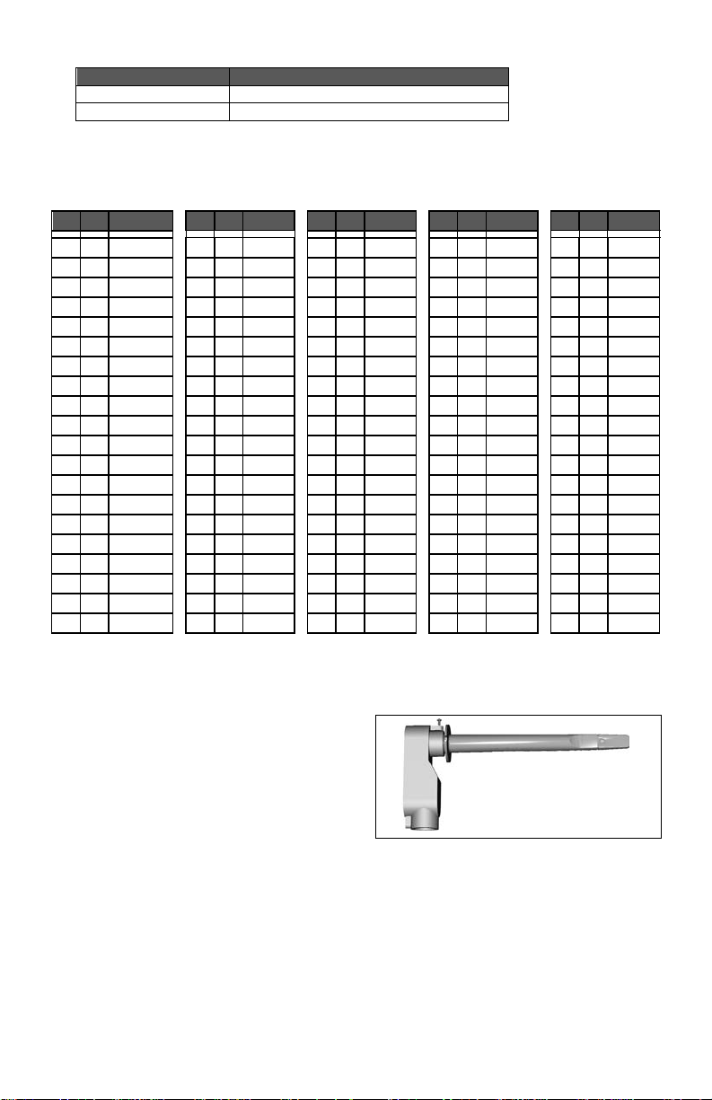
Page 38

DRAWING & DIMENSIONS
9245 Langelier Blvd. I St-Leonard I Quebec I Canada I H1P 3K9
Tel.: (514) 321.5660 I Fax: (514) 321.4150 Toll free: 1 800.563.5660
38 | VZ7260W Series- Installation Guide
Viconics Tech n ologies Inc.
sales@viconics.com I www.viconics.com
 Loading...