

Page 1
1
Zoning Product Series
VZ7260 & VZ7656 Series
For Commercial Zoning Systems
BACnet Integration Manual
ITG-VZ7xxx-BAC-E04.doc
(028-6011_R4 Issue Date: May 31st, 2012)
Page 2
2
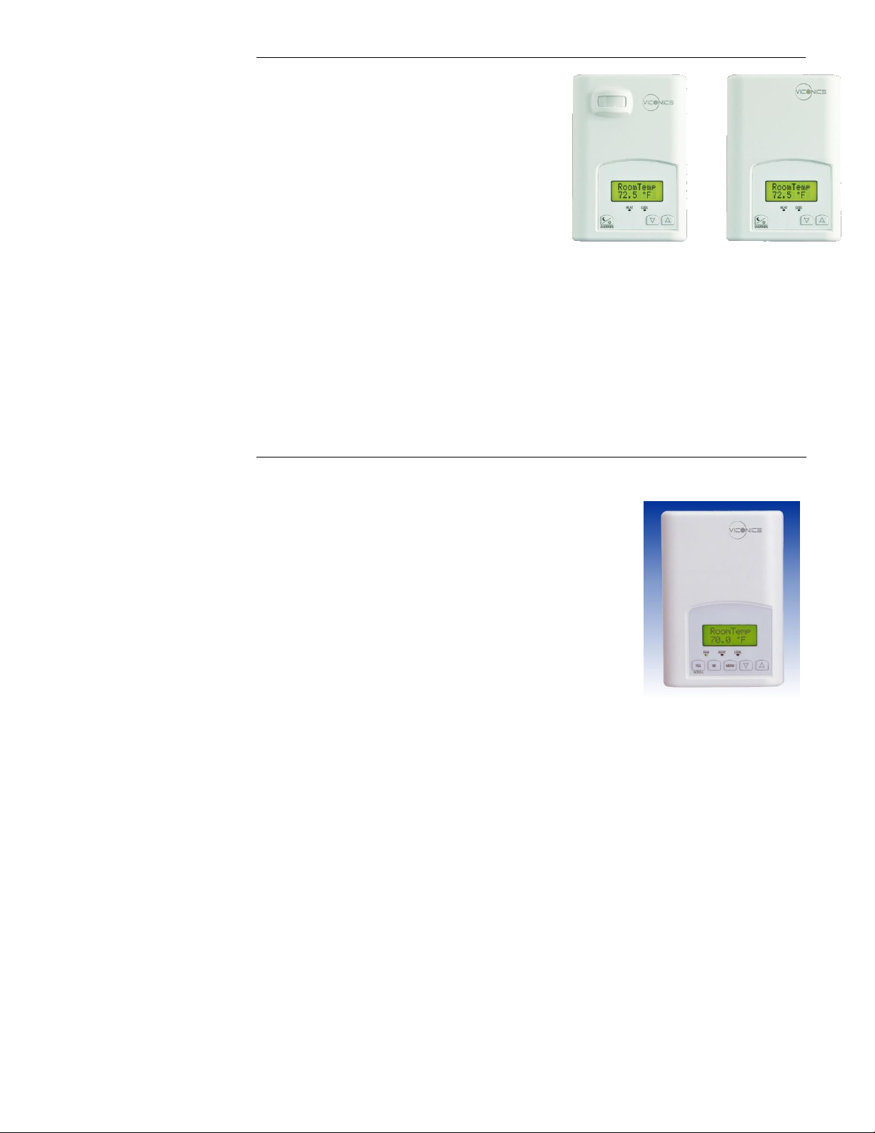
Fig.2 -VZ7656BController
VZ7260 Product Overview
The Viconics VZ7260 PI controller family is specifically designed for local
pressure dependent VAV zone control within Viconics Zoning System
product family.
The product features a backlit LCD display with dedicated function menu
buttons for simple user operation. Accurate temperature control is achieved
due to the product’s PI proportional control algorithm, which virtually
eliminates temperature offset associated with traditional, differential-based
controllers.
The controllers are used in conjunction with the Viconics VZ76561000B
Roof Top Controller for total system operation of each zones and the RTU.
A local BACnet RS485 MS-TP communication bus between all devices insures proper communication and data
exchange of all required information between the Zone controllers and RTU controller. They can be seamlessly
integrated into any 3rd party BACnet supervision system.
The Zone controllers are also compatible with the new Viconics PIR cover accessories. Controllers equipped with a
PIR cover provide advanced active occupancy logic, which will automatically switch occupancy levels from
occupied to stand-by as required by local activity being present or not. This advanced occupancy functionality
provides advantageous energy savings during occupied hours without sacrificing occupant comfort. All Zone
controllers can be ordered with or without a factory installed PIR cover (see ordering notes below).
VZ7656 Product Overview
The Viconics VZ7656 controller is specifically designed for RTU control of the Viconics
Zoning System product family.
The RTU controller is designed for single stage or multi-stage control of heating and
cooling equipment such as rooftop and self-contained units used in zoning systems.
The product features a backlit LCD display with dedicated function menu buttons for
simple user operation. Accurate temperature control is achieved due to the product’s PI
proportional control algorithm, which virtually eliminates temperature offset associated
with traditional, differential-based controllers.
The controller also contains extra digital inputs, which can be set by the user to monitor
filter status or used as a general purpose service indicator. All models contain a SPST
auxiliary switch, which can be used to control lighting or disable the RTU economizer
function during unoccupied periods. It also features a discharge air sensor input.
Proportional static pressure logic (input and output) has been integrated onto the
controller to provide a complete single packaged unit for most small to medium size jobs.
The controllers are used in conjunction with the Viconics VZ7260 Zone controllers for total system operation of
each zones and the RTU.
A local BACnet RS485 MS-TP communication bus between all devices insures proper communication and data
exchange of all required information between the Zone controllers and the RTU controllers. They can be
seamlessly integrated into any 3rd party BACnet supervision system.
Page 3
3
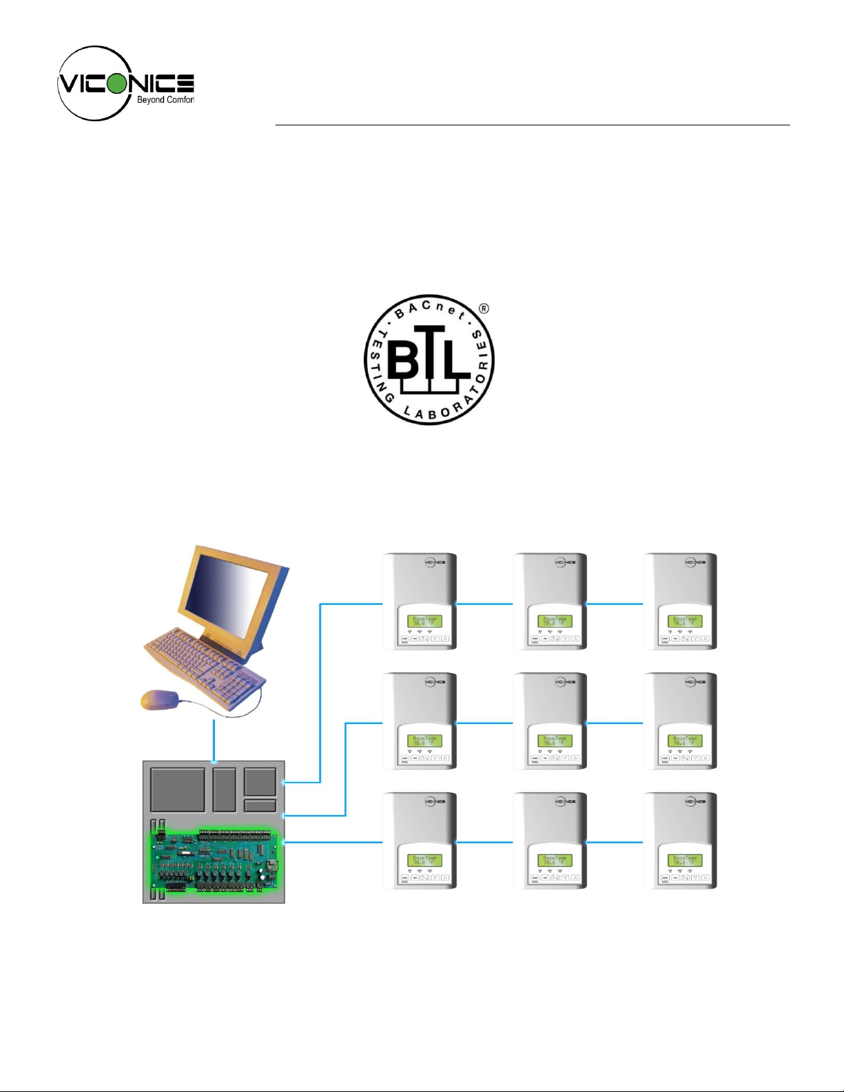
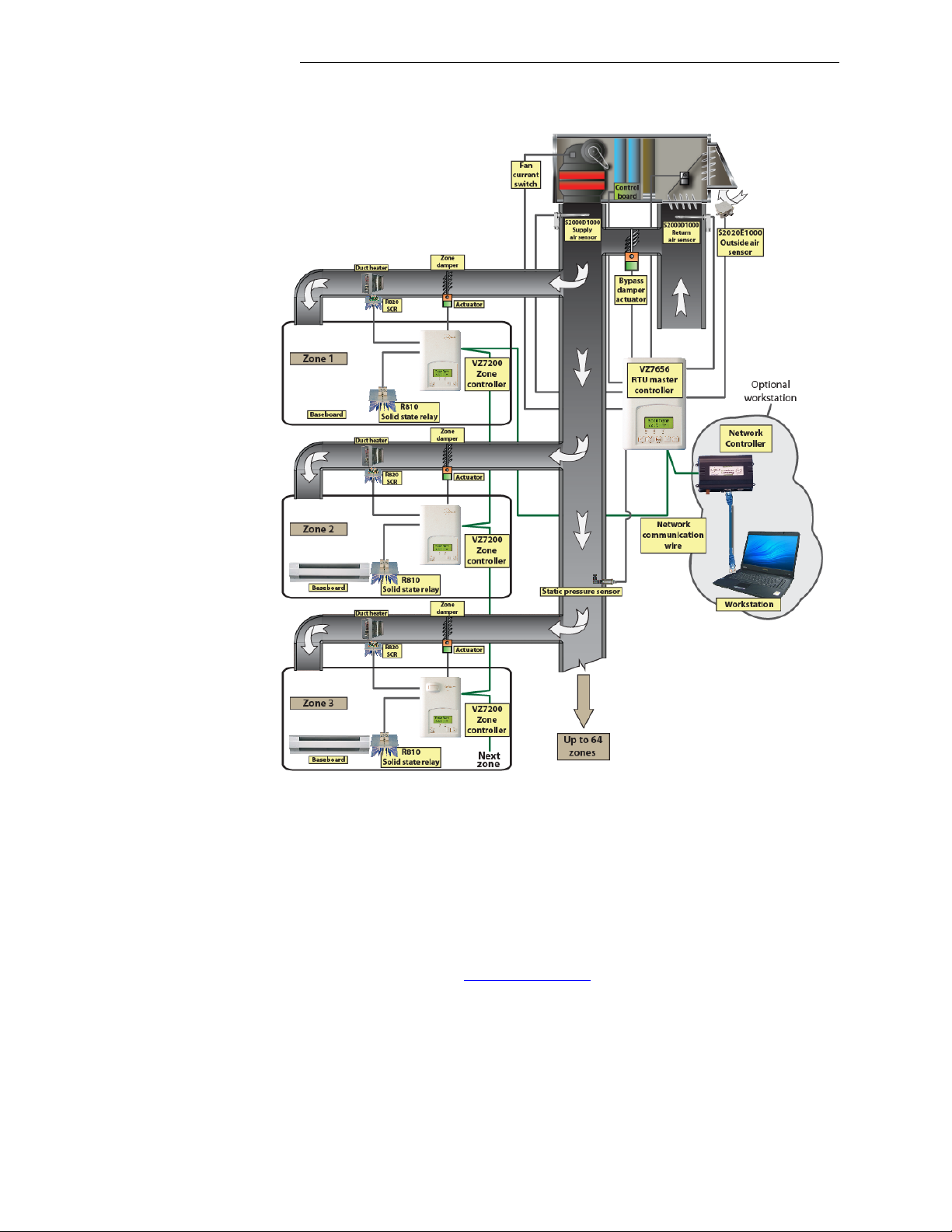
BACnet System Overview
Viconics VZ7260 zone controllers are used in conjunction with the VZ7656 roof top controllers. Combined, they
are designed for operate typical single or multistage RTUs and their associated local zones.
Typical BACnet zoning system installation
Please refer to the following Viconics documents for detailed information and design guidelines for the BACnet
zoning system version:
As an example, a typical job layout system may feature three RTU controllers with thirty one total zones. This
would bring to total number of nodes (individual Com addresses) to thirty four. RTU one would have ten zones
under its command, RTU two would have ten zones under its command and RTU three would have eleven
zones under its command.
The additional following documents are available at: www.viconics.com
For detailed information on the Viconics Zoning System, please refer to the Zoning System Product
Guide. Installation and commissioning information is available in document: Zoning-System-Guide-Exx
For detailed information on the Viconics VZ72 Zone controller, please refer and read the VZ72 Product
Guide. Installation and commissioning information is available on document: LIT-VZ7260-Exx
For detailed information on the Viconics VZ7656 RTU controller, please refer and read the VZ76 Product
Guide. Installation and commissioning information is available on document: LIT-VZ7656-Exx
PIR cover installation information is available in document: PIR Cover Installation-Exx
Page 4

4
Subject
VZ7260 series Protocol Implementation Conformance Statements (PICS)
Standard Object Types Supported
List of Proprietary Properties
List of Property Value Range
List of Property Enumeration Set for BI's and BV's
List of Property Enumeration Set for MV's
Integration
VZ7656 series Protocol Implementation Conformance Statements (PICS)
Standard Object Types Supported
List of Proprietary Properties
List of Property Value Range
List of Property Enumeration Set for BI's and BV's
List of Property Enumeration Set for MV's
Integration
Wiring Guide
Overview
Network Configuration
Maximum Number of Devices
Maximum Cable Length
EI-485 Repeaters
End Of Line Resistors
Network Adapter
Default Device Name and Device ID
Tips and Things You Need To Know
Troubleshooting Section
Document Control
Contents
Page 5

5
BACnet Interoperability Building Block
Data Sharing COV-B (DS-COV-B)
Data Sharing-ReadProperty-B (DS-RP-B)
Data Sharing-ReadPropertyMultiple-B (DS-RPM-B)
Data Sharing-WriteProperty-B (DS-WP-B)
Device Management-Dynamic Device Binding-B (DM-DDB-B)
Device Management-Dynamic Object Binding-B (DM-DOB-B)
Device Management-DeviceCommunicationControl-B (DM-DCC-B)
BACnet Interoperability Building Block
Data Sharing COV-A (DS-COV-A)
Data Sharing-ReadProperty-A (DS-RP-A)
Data Sharing-WriteProperty-A (DS-WP-A)
VZ7260 Series Protocol Implementation Conformance Statement (PICS)
Vendor Name: Viconics
Vendor ID: 140
Product Name: VZ7260 Zoning System Zone Controller
Product Model Number: VZ7260F5x00B
Product Description:
The Viconics VZ7260 PI controller family is specifically designed for local pressure dependent VAV zone control
within Viconics Zoning System product family.
The controllers are used in conjunction with the Viconics VZ76561000B Roof Top Controller for total system
operation of each zones and the RTU.
VZ7260 Supported BACnet Services
The BACnet communicating controller meets all requirements for designation as an Application Specific Controller
(B-ASC). The BACnet controller series supports the following BACnet Interoperability Building Blocks (BIBBs).
The following BACnet Interoperability Building Blocks supported are used ONLY with the VZ76561000B Roof Top
Controller for system operation. The following BiBBS are NOT listed under the “protocol service supported” device
attribute. As such, the VZ7260 application cannot use these services to communicate with “other” third party
devices (see Annex K in BACnet 2004):
Note: The controller does not support segmented requests or responses.
Page 6
6
Object Name
VZ7260F5x00B
VZ7260C5x00B
Object Property
Object Type
Instance #
GUI Damper Position
X
R AI
1
Cfg Zone MAC
X
X
R
AV 1 Cfg RTC MAC
X
X
R/W
AV
2
Cfg AO2 OA Lock Spt
X
R/W
AV
3
Cfg BO5 OA Lock Spt
X
X
R/W
AV
4
Cfg Damper Min Pos
X
X
R/W
AV
5
Cfg Damper Max Pos
X
X
R/W
AV
6
Cfg Damper Max Heat Pos
X
X
R/W
AV 7 Cfg Heating Stpt Limit
X
X
R/W
AV
8
Cfg Cooling Spt Limit
X
X
R/W
AV
9
Cfg Deadband
X
X
R/W
AV
10
GUI Occupied Heat Spt
X
X
R/W
AV
11
GUI Occupied Cool Spt
X
X
R/W
AV
12
GUI Unoccupied Heat Spt
X
X
R/W
AV
13
GUI Unoccupied Cool Spt
X
X
R/W
AV
14
GUI Stand-By Heat Spt
X
X
R/W
AV
15
GUI Stand-By Cool Spt
X
X
R/W
AV
16
GUI AO2 Status
X
R AV
17
GUI UI3 Status
X
X
R
AV
18
GUI PI Heat Weighted Demand
X
X
R
AV
19
GUI PI Cool Weighted Demand
X
X
R
AV
20
GUI Room Temperature
X
X
R
AV
21
GUI Outdoor Temperature
X
X
R/W
AV
22
Cfg Device Instance
X
X
R
AV
23
GUI PI Heat Demand
X
X
R
AV
24
GUI PI Cool Demand
X
X
R
AV
25
Cfg Password
X
X
R/W
AV
26
Cfg Stand-by Time
X
X
R/W
AV
27
Cfg Unoccupied Time
X
X
R/W
AV
28
GUI Heating Performance
X
X
R
AV
29
GUI Cooling Performance
X
X
R
AV
30
Cfg BO3-BO4 OA Lock Spt
X
R/W
AV
31
GUI Room CO2 Level
X
X
R/W
AV
32
GUI Transferred CO2 Value
X
X
R/W
AV
33
GUI AI4 Value
X
X
R
AV
34
GUI BI1 Status
X
X
R
BI
1
Device Object List for VZ7260 Models
Page 7
7
Object Name
VZ7260F5x00B
VZ7260C5x00B
Object Property
Object Type
Instance #
GUI BI1 Status
X
X
R
BI
1
Cfg Temperature Scale
X
X
R/W
BV
1
Cfg Menu Scroll
X
X
R/W
BV
2
Cfg AO2 DA/RA
X
R/W
BV 4 Cfg BO5 Time Base
X
X
R/W
BV
5
Cfg BO5 Conf
X
X
R/W
BV
6
GUI BO5 Status
X
X
R
BV
7
Sta AO2 Lock Status
X
R BV
8
Sta BO5 Lock Status
X
X
R
BV
9
GUI Room Temp Override
X
X
R/W
BV
10
Sta RTC Smart Recovery
X
X
R
BV
11
Cfg Setpoint Type
X
X
R/W
BV
12
Cfg Disable Min Pos
X
X
R/W
BV
13
Sta BO3-BO4 Lock Status
X R
BV
14
Cfg Zone Baud
X
X
R
MV
1
Cfg Reheat Config
X
X
R/W
MV 2 Cfg BI1 Configuration
X
X
R/W
MV
3
Cfg PI Heat Weight
X
X
R/W
MV
4
Cfg PI Cool Weight
X
X
R/W
MV
5
Cfg Temporary Occupancy Time
X
X
R
MV
6
Cfg Network Handle
X
X
R/W
MV
7
GUI Zone Keypad Lockout
X
X
R/W
MV 8 GUI Occupancy
X
X
R/W
MV
9
Sta RTC Zone Sequencing
X
X
R
MV
10
GUI Effective Occupancy
X
X
R
MV
11
Cfg BO1-BO2 Floating Time
X
R/W
MV
12
Cfg BO3-BO4 Floating Time
X
R/W
MV
13
Cfg AI4 Configuration
X
X
R/W
MV
14
Cfg Proportional Band
X
X
R/W
MV
15
Page 8
8
Object Name
VZ7656R1000B
VZ7656H1000B
VZ7656F1000B
VZ7656E1000B
Object Property
Object Type
Instance #
GUI Discharge Air Temp
X X X
X
R
AI 1 GUI Analog Heat Output
X R AI 5 GUI By-Pass Damper / VFD
X X X
X
R
AI 4 GUI Return Air Temp
X X X
X
R
AI 2 GUI Static Pressure
X X X
X
R
AI 3 Cfg RTC MAC
X X X
X
R
AV 1 Cfg Device Instance
X X X
X
R
AV
21
GUI Highest PI Cool Demand
X X X
X
R
AV
18
GUI Highest PI Heat Demand
X X X
X
R
AV
17
GUI CO2 Level
X
R
AV
40
GUI Current Zone PI Cool
Demand
X X X
X
R
AV
12
GUI Current Zone PI Heat
Demand
X X X
X
R
AV
11
GUI Economizer Output
X
R
AV
42
GUI Fresh Air Level
X
R
AV
39
GUI Highest CO2 Zone
X R
AV
41
GUI Highest PI Cool Zone
X X X
X
R
AV
16
GUI Highest PI Heat Zone
X X X
X
R
AV
15
GUI Supply PI Heat Demand
X R AV
28
GUI Transferred PI Cool
Demand
X X X
X
R
AV
14
GUI Transferred PI Heat
Demand
X X X
X
R
AV
13
Cfg Changeover Setpoint
X
R/W
AV
30
Cfg Cooling Lockout Temp
X X X
X
R/W
AV 3 Cfg Deadband
X X X
X
R/W
AV
22
Cfg Discharge High Limit Spt
X X X
X
R/W
AV
5
Cfg Discharge Low Limit Spt
X X X
X
R/W
AV
6
Cfg Economizer Max Position
X
R/W
AV
33
Cfg Economizer Min Position
X
R/W
AV
32
Cfg Fresh Air Max Range
X
R/W
AV
34
Device Object List for VZ7656 Models
Page 9
9
Object Name
VZ7656R1000B
VZ7656H1000B
VZ7656F1000B
VZ7656E1000B
Object Property
Object Type
Instance #
Cfg Heating Lockout Temp
X X X
X
R/W
AV 2 Cfg High Balance Point
X R/W
AV
24
Cfg Low Balance Point
X R/W
AV
25
Cfg Maximum CO2 Level
X
R/W
AV
38
Cfg Maximum Fresh Air
X
R/W
AV
36
Cfg Minimum CO2 Level
X
R/W
AV
37
Cfg Minimum Fresh Air
X
R/W
AV
35
Cfg Minimum Supply Heat
Setpoint
X
R/W
AV
26
Cfg Mixed Air Setpoint
X
R/W
AV
31
Cfg Password
X X X
X
R/W
AV
23
Cfg Power-up Delay
X X X
X
R/W
AV
20
Cfg Return Air Occ CL Spt
X X X
X
R/W
AV 7 Cfg Return Air Occ HT Spt
X X X
X
R/W
AV
9
Cfg Return Air Unocc CL
Spt
X X X
X
R/W
AV
8
Cfg Return Air Unocc HT
Spt
X X X
X
R/W
AV
10
Cfg Static Pressure Spt
X X X
X
R/W
AV
4
Cfg Supply Heat Lockout
Temperature
X
R/W
AV
27
GUI Outdoor Temperature
X X X
X
R/W
AV
19
GUI AUX Status
X X X
R BI 7 GUI BI Status
X X X
R BI 6 GUI G Fan
X X X
X
R
BI 1 GUI W1 Heat
X
X X
R
BI 4 GUI W2 Heat
X
X R
BI 5 GUI Y1 Compressor
X R
BI
16
GUI Y1 Cool
X X
X
R
BI 2 GUI Y2 Compressor
X R
BI
15
GUI Y2 Cool
X X
X
R
BI 3 Sta Clock Alarm
X X X
X
R
BI
12
Sta Cooling Lockout Status
X X X
X
R
BI 9 Sta Discharge Temp Alarm
X X X
X
R
BI
13
Sta Filter Alarm
X X X
X
R
BI
11
Sta Fresh Air Alarm
X R
BI
17
Page 10
10
Object Name
VZ7656R1000B
VZ7656H1000B
VZ7656F1000B
VZ7656E1000B
Object Property
Object Type
Instance #
Sta Heating Lockout Status
X X X
X
R
BI 8 Sta High CO2 Alarm
X R
BI
18
Sta Reversing Valve Status
X R
BI
14
Sta Service Alarm
X X X
X
R
BI
10
GUI Smart Recovery
X X X
X
R
BV 7 Sta Comm Lost Status
X X X
X
R
BV 3 Sta Supply Heat Lockout Status
X R BV
12
Cfg Aux Contact
X X X
R/W
BV 4 Cfg Compressor Interlock
X R/W
BV
11
Cfg Emergency Heat Mode
X R/W
BV 9 Cfg Fan Purge Delay
X X X
X
R/W
BV 5 Cfg Progressive Recovery
X X X
X
R/W
BV 2 Cfg Reversing Valve
X R/W
BV
10
Cfg Static Pressure Ctrl Type
X X X
X
R/W
BV 8 Cfg Units
X X X
X
R/W
BV 1 GUI Outdoor Temp Override
X X X
X
R/W
BV 6 Cfg RTC Baud
X X X
X
R
MV
1
GUI Zone Sequence
X X X
X
R
MV
4
Cfg BI1 Configuration
X X X
R/W
MV
11
Cfg CO2 Control Type
X R/W
MV
18
Cfg Control Type
X X X
X
R/W
MV
2
Cfg Cooling CPH
X X X
X
R/W
MV
9
Cfg Cooling Stages
X X
X
R/W
MV
7
Cfg Event Display
X X X
X
R/W
MV
13
Cfg Heat Pump Stages
X R/W
MV
16
Cfg Heating CPH
X
X X
R/W
MV
8
Cfg Heating Stages
X
X R/W
MV
6
Cfg Local Keypad Lockout
X X X
X
R/W
MV
3
Cfg Minimum On/Off Time
X X X
X
R/W
MV
10
Cfg Static Pressure Transducer
Range
X X X
X
R/W
MV
5
Cfg Temporary Occupied Time
X X X
X
R/W
MV
12
GUI System Mode
X X
X
R/W
MV
15
GUI System Mode HP
X R/W
MV
17
GUI Occupancy
X X X
X
R/W
MV
14
GUI Schedule
X X X
X
R
SCH
1
Page 11

11
Object Name
Type and
Instance
Object Property
Controller Parameter
VZ7260F5x00B
Device
Object_Identifier
Property 75 (R,W)
Unique ID number of a device on a network
Object_Name
Property 77 (R,W)
Unique name of a Device on a network
Model Name
Property 70 (R)
Controller Model number
Firmware Revision
Property 44 (R)
Current BACnet firmware revision used by the
controller
Protocol Version
Property 98 (R)
Current BACnet firmware protocol version
Default is Version 1
Protocol Revision
Property 139 (R)
Current BACnet firmware protocol revision
Default is Version 2
Max ADPU Length
Property 62 (R)
Maximum ADPU Length accepted
Default is 244
ADPU Timeout
Property 10 (R)
ADPU timeout value
Default is60 000 ms
Max_Master (R,W)
Maximum master devices allowed to be part of the
network. 0 to 127, default is 127
VZ7260 Device Object Table
Page 12

12
Object Type
Supported
Dynamically
Creatable
Dynamically
Removable
Optional
Properties
Supported
Writable Properties
Analog Input
Reliability
Out_of_Service
Analog Value
Reliability
Present_Valuea
Out_of_Service
Binary Input
Reliability
Active_Text
Inactive_Text
Out_of_Service
Binary Value
Reliability
Active_Text
Inactive_Text
Present_Valueb
Out_of_Service
Device
Max_Master
Max_Info_frames
Object_Identifier
Object_name
Max_Master
Multi-state Value
Reliability
States_Text
Present_Valuec
Out_of_Service
VZ7260 Standard Object Types Supported
a: Present_Value property is writable for every AV objects except :
Cfg Zone MAC (AV 1)
Cfg RTC MAC (AV 2)
GUI AO2 Status (AV 17)
GUI UI3 Status (AV 18)
GUI PI Heat Weighted Demand (AV 19)
GUI PI Cool Weighted Demand (AV 20)
GUI Room Temperature (AV 21) ( Present Value can be only be written if BV 10 GUI Room Temp
Override is set to true )
GUI Outdoor Temperature (AV 22)
Cfg Device Instance (AV 23) – This object is not writable even when OUT OF SERVICE is TRUE.
Changing the device ID will affect communication to the device even is OUT OF SERVICE is TRUE, so
it’s not recommended.
b: Present_Value property is writable for every BV objects except :
GUI BO5 Status (BV 7)
Sta AO2 Lock Status (BV 8)
Sta BO5 Lock Status (BV 9)
Sta RTC Prog Recovery (BV 11)
c: Present_Value property is writable for every MV objects except :
Cfg Zone Baud (MV 1)
GUI Occupancy (MV 9) ( Present Value can be only be written permanently if MV 7 Cfg Network
Handle is set to index 2 or 3. Index 1 resets present value as per application )
GUI Effective Occupancy (MV 11)
Page 13

13
Object name
Object Type
and instance
Under range
value
Over range
value
Default
value
GUI Damper Position
AI 1
0%
100%
N/A
Cfg Zone MAC
AV 1 1 255
255
Cfg RTC MAC
AV 2 1 127
4
Cfg AO2 OA Lock Setpoint
AV 3
-40°F (-40°C)
122°F (50°C)
55°F (13°C)
Cfg BO5 OA Lock Setpoint
AV 4
-40°F (-40°C)
122°F (50°C)
32°F (0°C)
Cfg Damper Min Pos
AV 5
0%
100%
10%
Cfg Damper Max Pos
AV 6
0%
100%
100%
Cfg Damper Max Heat Pos
AV 7
0%
100%
30%
Cfg Heating Spt Limit
AV 8
40°F (4.5°C)
90°F (32°C)
90°F (32°C)
Cfg Cooling Spt Limit
AV 9
54°F (12°C)
100°F (37.5)
54°F (12°C)
Cfg Deadband
AV 10
2°F (1°C)
5°F (2.5°C)
2°F (1°C)
GUI Occupied Heat Spt
AV 11
40°F (4.5°C)
90°F (32°C)
72°F (22°C)
GUI Occupied Cool Spt
AV 12
54°F (12°C)
100°F (37.5°C)
74°F (24°C)
GUI Unoccupied Heat Spt
AV 13
40°F (4.5°C)
90°F (32°C)
72°F (22°C)
GUI Unoccupied Cool Spt
AV 14
54°F (12°C)
100°F (37.5°C)
74°F (24°C)
GUI Stand-by Heat Spt
AV 15
40°F (4.5°C)
90°F (32°C)
62°F
(16.5°C)
GUI Stand-by Cool Spt
AV 16
54°F (12°C)
100°F (37.5°C)
80°F
(26.5°C)
GUI AO2 Status
AV 17
0%
100%
N/A
GUI UI3 Status
AV 18
-40°F (-40°C)
122°F (50°C)
N/A
GUI PI Heat Weighted
Demand
AV 19
0%
100%
N/A
GUI PI Cool Weighted
Demand
AV 20
0%
100%
N/A
GUI Room Temperature
AV 21
-40°F (-40°C)
122°F (50°C)
N/A
GUI Outdoor Temperature
AV 22
-40°F (-40°C)
122°F (50°C)
N/A
Cfg Device Instance
AV 23
72000
72255
N/A
GUI PI Heat Demand
AV 24
0%
100%
N/A
GUI PI Cool Demand
AV 25
0%
100%
N/A
Cfg Password
AV 26
0
1000
N/A
Cfg Stand-by Time
AV 27
0.5 hours
24 hours
0.5 hours
Cfg Unoccupied Time
AV 28
0 hours
24 hours
0 hours
GUI Heating Performance
AV 29
32°F (0°C)
100°F (37.5°C)
N/A
GUI Cooling Performance
AV 30
32°F (0°C)
100°F (37.5°C)
N/A
Cfg BO3-BO4 OA Lock Spt
AV 31
-40°F (-40°C)
122°F (50°C)
N/A
GUI Room CO2 Level
AV 32
0 PPM
2000 PPM
N/A
GUI Transferred CO2 Value
AV 33
0 PPM
2000 PPM
N/A
GUI AI4 Value
AV 34
0 VDC
10 VDC
N/A
VZ7260 List of Property Value Range Restrictions for AI and AV objects
Page 14

14
Object Name
Object Type and
instance
Inactive_Text
Active_Text
Default
value
GUI BI 1 Status
BI 1
Not Activated
Activated
Not Activated
GUI BI 2 Status
BI 2
Not Activated
Activated
Not Activated
Cfg Temperature Scale
BV 1
°C
°F
°F
Cfg Menu Scroll
BV 2
No Scroll
Scroll Active
Scroll Active
Cfg Motion Detector
Function
BV 3
Not Activated
Activated
Not Activated
Cfg AO2 RA/DA
BV 4
Direct Acting
Reverse
Acting
Direct Acting
Cfg BO5 Time Base
BV 5
15 Minutes
10 Seconds
15 Minutes
Cfg BO5 Configuration
BV 6
N.O.
N.C.
N.O.
GUI BO5 Status
BV 7
Off
On
Off
Sta AO2 Lock Status
BV 8
Not Activated
Activated
Not Activated
Sta BO5 Lock Status
BV 9
Not Activated
Activated
Not Activated
GUI Room Temp Override
BV 10
Normal
Override
Normal
Sta RTC Prog Recovery
BV 11
Off
On
Off
Cfg Setpoint Type
BV 12
Permanent
Temporary
Permanent
Cfg Disable Min Pos
BV 13
Enabled
Disabled
Disabled
Sta BO3-BO4 Lock Status
BV 14
Inactive
Active
Inactive
VZ7260 List of Property Enumeration Sets for BI and BV objects
Page 15

15
Object Name
Object
Type and
instance
BACnet Index
Text
Default value
Cfg Zone Baud
MV 1
1
9600 ( Bps )
Auto
2
19200 ( Bps )
3
38400 ( Bps )
4
76800 ( Bps )
5
Auto
Cfg Reheat
Configuration
MV 2
1
None
None
2
Analog Duct Heater
Only
3
On/Off Duct Heater
Only
4
On/Off Perimeter
Heater Only
5
Analog Duct Heater
with On/Off Perimeter
Heater
Cfg BI1
Configuration
MV 3
1
None
None
2
Motion NO
3
Motion NC
Cfg PI Heat Weight
MV 4
1
0 %
100 %
2
25 %
3
50 %
4
75 %
5
100 %
Cfg PI Cool Weight
MV 5
1
0 %
100 %
2
25 %
3
50 %
4
75 %
5
100 %
Cfg Temporary
Occupancy Time
MV 6
1
0 hour
2 hours
2
1 hour
3
2 hours
4
3 hours
5
4 hours
6
5 hours
7
6 hours
8
7 hours
9
8 hours
10
9 hours
11
10 hours
12
11 hours
13
12 hours
VZ7260 List of Property Enumeration Sets for MV Objects
Page 16

16
Object Name
Object
Type and
instance
BACnet Index
Text
Default value
Network Handle
MV 7
1
Default Zone Handle
Default Zone
Handle
2
Default Minus
Occupancy
3
Full Release
Network Handle
Occupancy
PI Heat
Weighted
PI Cool
Weighted
Prog Rec
Enabled
RTC
Sequence
1 = Default Zone
Handling
From the
VZ76
To the VZ76
To the VZ76
From the
VZ76
From the
VZ76
2 = Zone Handling
minus occupancy
To the VZ76
To the VZ76
From the
VZ76
From the
VZ76
3 = Full Release
The VZ7260 controller will operate without any dependencies from the VZ7656
RTU controller. It can be fully integrated with any supervision device for control
and operation
Object Name
Object
Type and
instance
BACnet Index
Text
Default value
Cfg Zone Keypad
Lockout
MV 8
1
Level 0
Level 0
2
Level 1
3
Level 2
4
Level 3
GUI Occupancy
Command
MV 9
1
Local Occupancy
Local Occupancy
2
Occupied
3
Unoccupied
Cfg RTC Zone
Sequencing
MV 10
1
Cool
Cool
2
Heat
GUI Effective
Occupancy
MV 11
1
Occupied
Depends on local
occupancy
2
Unoccupied
3
Temporary Occupied
4
Stand-by
Cfg BO1-BO2
Floating Time
MV 12
1
0.5 minutes
1. 5 minutes
2
1 minute
3
1.5 minutes
4
2 minutes
5
2.5 minutes
6
3 minutes
7
3.5 minutes
8
4 minutes
9
4.5 minutes
10
5 minutes
11
5.5 minutes
12
6 minutes
13
6.5 minutes
14
7 minutes
15
7.5 minutes
16
8 minutes
17
8.5 minutes
18
9 minutes
This property is used to release the functions of the VZ7260 Zone controller from its attached master RTC VZ7656. It is used
when remote scheduling of the zones are required externally to the master VZ7656 RTU controller or when integration is
required without a VZ7656 RTU controller.
Page 17

17
Object Name
Object
Type and
instance
BACnet Index
Text
Default value
Cfg BO3-BO4
Floating Time
MV 13
1
0.5 minutes
1.5 minutes
2
1 minute
3
1.5 minutes
4
2 minutes
5
2.5 minutes
6
3 minutes
7
3.5 minutes
8
4 minutes
9
4.5 minutes
10
5 minutes
11
5.5 minutes
12
6 minutes
13
6.5 minutes
14
7 minutes
15
7.5 minutes
16
8 minutes
17
8.5 minutes
18
9 minutes
Cfg A14
Configuration
MV 14
1
None
None
2
CO2
Cfg Proportional
Band
MV 15
1
3°F(1.7°C)
3°F(1.7°C)
2
4°F(2.2°C)
3
5°F(2.8°C)
4
6°F(3.3°C)
5
7°F(3.9°C)
6
8°F(4.4°C)
7
9°F(5.0°C)
8
10°F(5.6°C)
Page 18

18
VZ7260 Integration
Please note that no special programming or network bindings are required for the Zoning system to operate. As
such the VZ7260 Zone controllers and their associated VZ7656 RTU controller can operate in stand-alone mode
with all required data transfer binding already handled by the controllers themselves. If BACnet supervision is
added, it is only for GUI, trends, logs or remote views of the devices. The zoning system operation is already taken
care of by the controllers themselves.
The example showed below is valid on MV 7 (Network Handle) index being: 1 – Default Zone Handle. As such
outdoor temperature, Zone mode and Zone Occupancy are NOT dependent on the BAS font end and are objects
dependent on the attached VZ76561000B RTU controller
All object names staring with a “GUI” prompt are normally used for graphic GUI views.
All object names staring with a “Sta” prompt are Status normally used for graphic GUI views.
All object name staring with a “Cfg” prompt are associated to configuration properties of the controller and
typically do not need to be associated to any GUI views
If your BAS allows you to remove objects from your database, Viconics recommends removing all configuration
objects once your setup is complete. This will prevent unnecessary polling of non-used objects and will help speed
up your network.
The following figure shows the typical objects from the controller which can be monitored and commanded from a
BAS front-end.
The following objects could be typically used in a GUI:
Room Temperature (AV 21);
Occupied, Stand-by and Unoccupied Heat Setpoints (AV 11, AV 13 and AV 15);
Occupied, Stand-by and Unoccupied Cool Setpoints (AV 12, AV 14 and AV 16);
Outdoor Temperature (AV 22); Value from VZ7656
UI3 Status / Supply Temperature (AV 18) (If available);
Occupancy Command (MV 9); Value from VZ7656
RTC Zone Sequencing (MV 10);
Damper Position (AI 1);
AO2 Status (AV 17);
PI Heat Demand & Weighted PI Heat Demand (AV 19 & AV 24)
PI Cool Demand & Weighted PI Cool Demand (AV 20 & AV 25)
Page 19

19
BACnet Interoperability Building Block
Data Sharing COV-B (DS-COV-B)
Data Sharing-ReadProperty-B (DS-RP-B)
Data Sharing-ReadPropertyMultiple-B (DS-RPM-B)
Data Sharing-WriteProperty-B (DS-WP-B)
Device Management-Dynamic Device Binding-B (DM-DDB-B)
Device Management-Dynamic Object Binding-B (DM-DOB-B)
Device Management-DeviceCommunicationControl-B (DM-DCC-B)
Device Management-TimeSynchronisation-B (DM-TS-B)
Scheduling-Readonly-B (SCHED-R-B)
VZ7656 Series Protocol Implementation Conformance Statement (PICS)
Vendor Name: Viconics
Vendor ID: 140
Product Name: VZ7656 Zoning System RTU Controller
Product Model Number: VZ76561000B
Product Description:
The Viconics VZ76561000B controller is specifically designed for RTU control of the Viconics Zoning System
product family.
The RTU controller is designed for single stage or multi-stage control of heating and cooling equipment such as
rooftop and self-contained units used in zoning systems.
The controllers are used in conjunction with the Viconics VZ7260F5x00B Zone controllers for total system
operation of each zones and the RTU.
VZ7656 Supported BACnet Services
The BACnet communicating controller meets all requirements for designation as an Application Specific Controller
(B-ASC). The BACnet controller series supports the following BACnet Interoperability Building Blocks (BIBBs).
Note: The controller does not support segmented requests or responses.
Page 20

20
Object Name
Type and
Instance
Object Property
Controller Parameter
VZ7656
Device
Object_Identifier
Property 75 (R,W)
Unique ID number of a device on a network
Object_Name
Property 77 (R,W)
Unique name of a Device on a network
Model Name
Property 70 (R)
Controller Model number
Firmware Revision
Property 44 (R)
Current BACnet firmware revision used by the
controller
Protocol Version
Property 98 (R)
Current BACnet firmware protocol version
Default is Version 1
Protocol Revision
Property 139 (R)
Current BACnet firmware protocol revision
Default is Version 2
Max ADPU Length
Property 62 (R)
Maximum ADPU Length accepted
Default is 244
ADPU Timeout
Property 10 (R)
ADPU timeout value
Default is60 000 ms
Max_Master (R,W)
Maximum master devices allowed to be part of the
network. 0 to 127, default is 127
VZ7656 Device Object Table
Page 21

21
Object Type
Supported
Dynamically
Creatable
Dynamically
Removable
Optional
Properties
Supported
Writable Properties
Analog Input
Reliability
Out_of_Service
Analog Value
Reliability
Present_Valuea
Out_of_Service
Binary Input
Reliability
Active_Text
Inactive_Text
Out_of_Service
Binary Value
Reliability
Active_Text
Inactive_Text
Present_Valueb
Out_of_Service
Device
Max_Master
Max_Info_frames
Object_Identifier
Object_name
Max_Master
Multi-state Value
Reliability
States_Text
Present_Valuec
Out_of_Service
Schedule
Weekly_schedule
Read Only
VZ7656 Standard Object Types Supported
a: Present_Value property is writable for every AV objects except :
Cfg RTC MAC (AV 1)
GUI Current Zone PI Heat Demand (AV 11)
GUI Current Zone PI Cool Demand (AV 12)
GUI Transferred PI Heat Demand (AV 13)
GUI Transferred PI Cool Demand (AV 14)
GUI Highest PI Heat Zone (AV 15)
GUI Highest PI Cool Zone (AV 16)
GUI Highest PI Heat Demand (AV 17)
GUI Highest PI Cool Demand (AV 18)
Cfg Device Instance (AV 21)
b: Present_Value and Out_of_Service properties are writable for every BV objects except :
Sta Comm Lost Status (BV 3)
Sta Smart Recovery (BV 7)
c: Present_Value and Out_of_Service properties are writable for every MV objects except :
Cfg RTC Baud (MV 1)
GUI Zone Sequence (MV 4)
Page 22

22
Object name
Object Type
and instance
Under range
value
Over range
value
Default value
GUI Discharge Air Temp
AI 1
-40°F (-40°C)
150°F (65°C)
N/A
GUI Return Air Temp
AI 2
-40°F (-40°C)
122°F (50°C)
N/A
GUI Static Pressure Input
AI 3
0” WC
(0 Pa)
5” WC
(1250 Pa)
N/A
GUI By-Pass Damper
AI 4
0%
100%
N/A
Cfg RTC MAC
AV 1
1
255
4
Cfg Heating Lockout
Temperature
AV 2
-15°F (-26°C)
120°F (49°C)
120°F (49°C)
Cfg Cooling Lockout
Temperature
AV 3
-40°F (-40°C)
95°F (35°C)
-40°F (-40°C)
Cfg Static Pressure Spt
AV 4
0” WC
(0 Pa)
2” WC
(500 Pa)
0.8” WC
(200 Pa)
Cfg Discharge High Limit Spt
AV 5
70°F (21°C)
150°F (65°C)
120°F (49°C)
Cfg Discharge Low Limit Spt
AV 6
35°F (2°C)
65°F (19°C)
45°F (7°C)
Cfg Return Air Occ Cool Spt
AV 7
54°F (12°C)
100°F (37.5°C)
74°F (24°C)
Cfg Return Air Unocc Cool Spt
AV 8
54°F (12°C)
100°F (37.5°C)
74°F (24°C)
Cfg Return Air Occ Heat Spt
AV 9
40°F (4.5°C)
90°F (32°C)
72°F (22°C)
Cfg Return Air Unocc Heat Spt
AV 10
40°F (4.5°C)
90°F (32°C)
72°F (22°C)
GUI Current Zone
PI Heat Demand
AV 11
0%
100%
N/A
GUI Current Zone
PI Cool Demand
AV 12
0%
100%
N/A
GUI Transferred PI Heat Demand
AV 13
0%
100%
N/A
GUI Transferred PI Cool Demand
AV 14
0%
100%
N/A
GUI Highest PI Heat Zone
(Com Address)
AV 15
0
255
N/A
GUI Highest PI Cool Zone
(Com Address)
AV 16
0
255
N/A
GUI Highest PI Heat Demand
AV 17
0%
100%
N/A
GUI Highest PI Cool Demand
AV 18
0%
100%
N/A
GUI Outdoor Temperature
AV 19
-40°F (-40°C)
122°F (50°C)
N/A
Cfg Power Delay
AV 20
10 Seconds
120 Seconds
30 Seconds
Cfg Device Instance
AV 21
76000
76255
N/A
Cfg Deadband
AV 22
2°F (1°C)
4°F (2°C)
2°F (1°C)
Cfg Password
AV 23
0
1000
N/A
Cfg High Balance Point
AV 24
34°F(1°C)
90°F(32°C)
90°F(32°C)
Cfg Low Balance Point
AV 25
-40°F(1°C)
-40°F(32°C)
-40°F(-40°C)
Cfg Minimum Supply Heat
Setpoint
AV 26
50°F(1°C)
72°F(32°C)
64°F(18°C)
VZ7656 List of Property Value Range Restrictions for AI and AV objects
Page 23

23
Cfg Supply Heat Lockout
AV 27
-15°F(-26°C)
120°F(49°C)
32°F(0°C)
GUI Supply PI Heat Demand
AV 28
0%
100%
N/A
Cfg Changeover Setpoint
AV 30
14°F(-26°C)
70°F(-26°C)
55°F(13°C)
Cfg Mixed Air Setpoint
AV 31
50°F(10°C)
90°F(32°C)
55°F(13°C)
Cfg Economizer Min Position
AV 32
0%
100%
0%
Cfg Economizer Max Position
AV 33
0%
100%
100%
Cfg Fresh Air Max Range
AV 34
0 CFM (0 l/s)
20000 CFM
(9440 l/s)
0 CFM (0 l/s)
Cfg Minimum Fresh Air
AV 35
0 CFM (0 l/s)
20000 CFM
(9440 l/s)
0 CFM (0 l/s)
Cfg Maximum Fresh Air
AV 36
0 CFM (0 l/s)
20000 CFM
(9440 l/s)
0 CFM (0 l/s)
Cfg Minimum CO2 Level
AV 37
0 PPM
2000 PPM
800 PPM
Cfg Maximum CO2 Level
AV 38
0 PPM
2000 PPM
1200 PPM
GUI Fresh Air Level
AV 39
0 CFM (0 l/s)
20000 CFM
(9440 l/s)
N/A
GUI CO2 Level
AV 40
0 PPM
2000 PPM
N/A
GUI Highest CO2 Zone
AV 41
1
127
N/A
GUI Economizer Output
AV 42
0%
100%
N/A
Note:
The GUI Current Zone PI Heat & Cool Demand objects represent the actual calculated average demand values from either the
highest, the demands of the actual highest 3 zones or the demands of the actual highest 5 zones as per selected by MV2
Control Type object.
Page 24

24
Object Name
Object Type and
instance
Inactive_Text
Active_Text
Default
value
GUI G Fan
BI 1
Off
On
N/A
GUI Y1 Cool
BI 2
Off
On
N/A
GUI Y2 Cool
BI 3
Off
On
N/A
GUI W1 Heat
BI 4
Off
On
N/A
GUI W2 Heat
BI 5
Off
On
N/A
GUI BI 1 Status
BI 6
Not Activated
Activated
Not Activated
GUI Aux Status
BI 7
Off
On
N/A
Sta Heating Stages Lockout
Status
BI 8
Not Activated
Activated
Not Activated
Sta Cooling Stages Lockout
Status
BI 9
Not Activated
Activated
Not Activated
Sta Service Alarm
BI 10
Off
On
Off
Sta Filter Alarm
BI 11
Off
On
Off
Sta Clock Alarm
BI 12
Off
On
Off
Sta Discharge Temp Alarm
BI 13
Off
On
Off
Sta Reversing Valve Status
BI 14
Off
On
Off
GUI Y2 Compressor
BI 15
Off
On
Off
GUI Y1 Compressor
BI 16
Off
On
Off
Sta Fresh Air Alarm
BI 17
Off
On
Off
Sta High CO2 Alarm
BI 18
Off
On
Off
Cfg Units
BV 1
°C / SI Units
°F / Imperial
Units
°F / Imperial
Units
Cfg Progressive Recovery
BV 2
Off
Active
Off
Sta Com Lost Status
BV 3
Down
Up
N/A
Cfg Aux Contact
BV 4
N.O.
N.C.
N.O.
VZ7656 List of Property Enumeration Sets for BI and BV objects
Page 25

25
Cfg Fan Purge Delay
BV 5
Off
On
Off
GUI Outdoor Temp
Override
BV 6
Normal
Override
Normal
Cfg Smart Recovery
BV 7
Off
Active
Off
Cfg Static Pressure Ctrl
Type
BV 8
By-Pass
Damper
VFD
VFD
Cfg Emergency Heat Mode
BV 9
Off
On
On
Cfg Reversing Valve
BV 10
Normally Cool
Normally
Heat
Normally
Heat
Cfg Compressor Interlock
BV 11
Off
On
On
Sta Supply Heat Lockout
Status
BV 12
Inactive
Active
Active
Page 26

26
Object Name
Object
Type and
instance
BACnet Index
Text
Default value
Cfg RTC Baud
MV 1
1
9600 ( Bps )
Auto
2
19200 ( Bps )
3
38400 ( Bps )
4
76800 ( Bps )
5
Auto
Cfg Control Type
MV 2
1
Highest
AV_H3 /Average
of Highest 3
Zones
2
AV_H3 /Average of
Highest 3 Zones
3
AV_H5 /Average of
Highest 5 Zones
Cfg Local Keypad
Lockout
MV 3
1
Level 0 / No Lockout
Level 0 / No
Lockout
2
Level 1
3
Level 2
GUI Zone
Sequence
MV 4
1
Off / Never used
Cool
2
Cool
3
Heat
Cfg Static Pressure
Transducer Range
MV 5
1
0 to 1.5“ of WC
0 to 1.5“ of WC
2
0 to 2.0“ of WC
3
0 to 3.0“ of WC
4
0 to 4.0“ of WC
5
0 to 5.0“ of WC
Cfg Heating Stages
MV 6
1
1 Stage
2 Stages
2
2 Stages
Cfg Cooling Stages
MV 7
1
1 Stage
2 Stages
2
2 Stages
Cfg Heating CPH
MV 8
1
3 CPH
4 CPH
2
4 CPH
3
5 CPH
4
6 CPH
5
7 CPH
6
8 CPH
Cfg Cooling CPH
MV 9
1
3 CPH
4 CPH
2
4 CPH
Cfg Min. On/Off
Time
(Anticycle)
MV 10
1
0 minute
2 minutes
2
1 minute
3
2 minutes
4
3 minutes
5
4 minutes
6
5 minutes
VZ7656 List of Property Enumeration Sets for MV Objects
Page 27

27
Object Name
Object
Type and
instance
BACnet Index
Text
Default value
Cfg BI1
Configuration
MV 11
1
None
None
2
RemNSB
3
RemOVR
4
Filter
5
Service
Cfg Temporary
Occupancy Time
MV 12
1
0 hour
2 hours
2
1 hour
3
2 hours
4
3 hours
5
4 hours
6
5 hours
7
6 hours
8
7 hours
9
8 hours
10
9 hours
11
10 hours
12
11 hours
13
12 hours
Cfg Event Display
MV 13
1
2 Events
2 Event
2
4 Events
GUI Occupancy
MV 14
1
Local Occupancy
Local Occupancy
2
Occupied
3
Unoccupied
GUI System Mode
MV 15
1
Off
Auto
2
Auto
Cfg Heat Pump
Stages
MV 16
1
1 Stage
2 Stages
2
2 Stages
GUI System Mode
HP
MV 17
1
Off
Auto
2
Auto
3
Cool
4
Heat
5
Emergency Heat
Cfg CO2 Control
Type
MV 18
1
Highest
AV_H3
2
AV_H3
3
AV_H5
Page 28

28
(BI 38)
(BI 25)
(BI 26)
(BI 27)
(BI 28)
(BI 29)
(MV 12)
(MV 14)
(BI 24)
(BI 31)
( B I 3 2 )
(BI 36)
(BI 39)
(AI 16)
(AV 42)
(AV 43)
(AV 44)
(AV 45)
Return Air Temperture (AI 2)
VZ7656 Integration
Please note that no special programming or network bindings are required for the Zoning system to operate. As
such the VZ7260 Zone controllers & their associated VZ7656 RTU controller can operate in stand-alone mode with
all required data transfer binding already handled by the controllers themselves. If BACnet supervision is added, it
is only for GUI, trends, logs or remote views of the devices. The zoning system operation is already taken care of
by the controllers.
All object names staring with a “GUI” prompt are normally used for graphic GUI views.
All object names staring with a “Sta” prompt are Status normally used for graphic GUI views.
All object name staring with a “Cfg” prompt are associated to configuration properties of the controller and
typically do not need to be associated to any GUI views
If your BAS allows you to remove objects from your database, Viconics recommends removing all configuration
objects once your setup is complete. This will prevent unnecessary polling of non used objects and will help speed
up your network.
The following figure shows the typical objects from the controller can be monitored and commanded from a BAS
front-end.
The following objects could be typically used in a GUI:
Return Air Temperature (AI 2); Outdoor Temperature (AV 19); Discharge Air Temperature (AI 1)
Return Air Occupied and Unoccupied Heat Setpoints (AV 9 and AV 10);
Return Air Occupied and Unoccupied Cool Setpoints (AV 7 and AV 8);
Static Pressure & Static Pressure Setpoint (A1 3 and AV 4)
Occupancy (MV 14); System Mode (MV 15); Zone Sequence (MV 4);
G Fan (BI 1); Y1 Cool (BI 2); Y2 Cool (BI 3); W1 Heat (BI 4); W2 Heat (BI 5);
Aux Status (BI 7); BI 1 Status (BI 6);
Filter Alarm (BI 11) (if available); Service Alarm (BI 10) (if available);
Discharge Air Temperature Alarm (BI 13)
Current Zone PI Heat Demand (AV 11);
Current Zone PI Cool Demand (AV 12);
Page 29

29
Parameter
Details
Media
Twisted pair 22AWG-24 AWG, shielded recommended
Characteristic Impedance
100-130 ohms
Distributed capacitance
Less than 100 pF per meter (30 pF per foot)
Maximum length per segment
1200 meters (4000 feet) Note: AWG 18 cable
Polarity
Polarity sensitive
Multi-drop
Daisy-chain (no T connections)
Terminations
1. Viconics’ devices are installed at both ends of the
MSTP network:
120 Ohms resistor should be installed at each end.
2. A Viconics device is installed at one end of the MSTP
network and a 3rd party device is installed at the other
end:
Install an End-Of-Line resistor value that matches the 3 rd
party device instruction regarding the End-Of-Line resistors
3. 3rd party devices are installed at both ends of the MSTP
network:
Follow the 3rd party device instructions regarding the EndOf-Line resistors.
Network Bias Resistors
510 ohms per wire (max. of two sets per segment)
Maximum number of nodes per
segment
64 (Viconics devices only)
Maximum number of nodes per
network
128
Baud rate
9600, 19200, 38400, 76800 (Auto detect)
Wiring Guide Overview
Viconics uses EIA-485 as the physical layer between their devices and supervisory controllers.
For clarity we will use the term “Device” to represent any product with an active EIA-485 network connection,
including Viconics and non-Viconics controllers.
Summary Specifications:
Table 1: Summary of Specifications for a Viconics’ EIA-485 Network
Page 30

30
Cable Type
Viconics recommends the use of balanced 22-24 AWG twisted pair with characteristic impedance of 100-130
ohms, capacitance of 30 pF per ft or lower. A braided shield is recommended.
Impedance
A value based on the inherent conductance, resistance, capacitance and inductance that represent the impedance
of an infinitely long cable. The nominal impedance of the cable should be between 100Ωand 120Ω. However
using120Ω will result in a lighter load on the network.
Capacitance (pF per ft)
The amount of equivalent capacitive load of the cable, typically listed in a per foot basis. One of the factors limiting
total cable length is the capacitive load. Systems with long lengths benefit from using low capacitance cable (i.e.
17pF per ft or lower).
Network Configuration
EIA-485 networks use a daisy chain configuration. A daisy chain means that there is only one main cable and
every network device is connected directly along its path.
(Figure 3) illustrates two improper network configurations and the proper daisy chain configuration.
Other methods of wiring an EIA-485 network may give unreliable and unpredictable results. There are no
troubleshooting methods for these types of networks. Therefore, a great deal of site experimentation may have to
be done, making this a difficult task with no guarantee of success. Viconics will only support daisy chain
configurations.
Figure 3: Three different network configurations: star, bus, and daisy chain. Only the daisy
chain configuration is correct for an EIA-485 network.
Page 31

31
Maximum Number of Devices
A maximum of 64 nodes is allowed on a single daisy chain segment. A node is defined as any device (Panel,
Zone, Repeater, etc) connected to the RS485 network. Terminators do not count as a node.
To determine the number of nodes on a network, add the following:
One node for each device, including main panels
One node for each repeater on the chain
For the example in (Figure 4), we have one node for the main Panel, plus 4 for the controllers, for a total of 5
nodes.
Figure 4: Five nodes network example.
If you have more than 64 devices, then repeaters are required to extend the network.
Maximum Cable Length
The maximum length of a chain is related to its transmission speed. The longer the chain the slower the speed
of transmission will be. Using proper cable, the maximum length of an EIA-485 daisy chain is 4000-ft (1200
m). This will only work reliably for data rates up to 100,000 bps. Viconics’ maximum data rate is 76,800 bps.
If you require a maximum network length of more than 4000 feet, then repeaters are required to extend the
network.
EIA-485 Repeaters
If you have more than 64 devices, or require a maximum network length of more than 4000 feet, then
repeaters are required to extend the network. The best configuration is to daisy chain the repeaters to the
main panel. From each of these repeaters, a separate daisy chain will branch off. (Figure 5) demonstrates a
valid use of repeaters in an EIA-485 network.
Page 32

32
Figure 5: Correct usage – repeaters are daisy chained to the supervisory controller
and separate daisy chains branch from each repeater.
Do not install repeaters in series, as this may result in network reliability problems. (Figure 6) demonstrates an
incorrect use of a repeater in an EIA-485 network.
Figure 6: Incorrect usage – the second repeater in series may result in an
unreliable system
Page 33

33
End of Line (EOL) Resistors
MS/TP network must be properly terminated. For daisy chain configurations, you must install an EOL resistor at
each end of the daisy chain. Depending on your MSTP network configuration, the resistance value of the EOL
resistor may change:
Viconics’ devices are installed at both ends of the MSTP network:
120 Ohms resistor should be installed at each end.
A Viconics device is installed at one end of the MSTP network and a 3rd party device is installed at the
other end:
Install an End-Of-Line resistor value that matches the 3rd party devices instructions regarding its EOL
resistor value.
3rd party devices are installed at both ends of the MSTP network:
Follow the 3rd party devices instructions regarding its EOL resistor value.
Network Adapter
The polarity of the connection to the cable is important. From one module to the other it is important that the same
coloured wire be connected to “plus” or “+” and the other coloured wire be connected to the “minus” or ”-“. (Figures
7) shows the proper MS/TP connections and the location of the Status LED. This Status LED may help to
troubleshoot network problems.
Figure 7: Correct MS/TP connections and location of a Status LED on a BACnet module
IMPORTANT NOTE: The Ref terminal should NEVER be used to wire shields. The 2 shields from each feed of the
network connection to a controller should be wired together in the back of the controller and properly protected to
prevent any accidental connection to the ground.
The joined shield connection should then be grounded at a single point on the whole segment. More than one
ground connection to a shielded wire may induce ground loop noises and affect communication.
Page 34

34
Condition of the Status LED
Possible Cause
Solution
2 short blink (no wires
connected to the module)
Controller is searching for an MSTP BACnet network. Either at
selected Baud rate or is currently
Auto-Bauding
Connect Controller to
Network
2 short blink (wires
connected to the module)
Module is not at the same baud
rate as the network or set at a
different Baud rate than Main
network
If Auto-Bauding, power off
and on the controller.
If wrong Baud rate is
selected, match network
Baud rate for each device.
2 short blinks and a longer
blink (wires connected to
the module)
The module has detected the
presence of a network and is in the
Token Pass of the ring
N/A
Table 2 shows the different possibilities with the Status LED behaviour of the BACnet module.
Table 2: Status LED condition and possible solutions
Default Device Name and default Device ID
Default Device Name is set to: Model number – MAC:
Where MAC is the current MAC address of the device.
Where Model number is Viconics part number.
The device name will be upgraded as soon as there is a change to the device MAC address.
Default Device ID is set to: 76000 + MAC
Where MAC is the current MAC address of the device.
The device ID will also be upgraded as soon as there is a change to the device’s MAC.
For an RTU controller example, when a VZ76561000B controller with a MAC address of 63 is connected to a
network, its default Device Name will be VZ76561000B-63 and its default Device ID will be 76063.
For a zone controller example, when a VZ7260F5x00B controller with a MAC address of 12 is connected to a
network, its default Device Name will be VZ7260F5x00B-12 and its default Device ID will be 72012.
Device Name and Device ID properties are writable in Viconics’ device object. Both properties can be renamed
from any BACnet network management tool as long as the tool itself can write to these properties.
Page 35

35
Error / Trouble
Condition
Possible Cause
Solution
Controller does not
come online
Two or more controllers have the same
MAC address.
Modify each duplicate address to a
unique number.
The MS/TP network has too many
devices.
Do not exceed the maximum number of
devices and maximum length allowed
by the EIA-485 specifications.
Too many devices were installed
without any repeaters.
Repeaters need to be installed as
specified in this document.
The MS/TP cable runs are broken
Locate the break and correct wiring
MS/TP connections at the module
were reversed
Respect polarity of the wires on a
MS/TP network.
The controller does not have power
Apply power to the controller
Things You Need To Know
After the initial configuration of your device and if your BAS allows you to remove objects, we suggest
that you remove all the configuration objects to prevent unnecessary polling of non used objects and to
help speed up the network.
In its default mode of operation (Auto-Bauding), the device will automatically match its baud rate to the
baud rate of the network. Automatic baud rate detection will occur when the MS/TP communication
port is initialized (on power up). If the network speed is changed, the device will keep listening at the
previously detected speed for 2.5 minutes before resuming auto-bauding. Re-powering the devices will
force right away auto-bauding.
If the device should go off-line, the following binded controller parameters will be released:
Room Temperature
Outdoor Temperature
Occupancy
The BACnet Data Link layer has two key parameters: the device object name and the device object ID.
The device object name must be unique from any other BACnet device object name on the BACnet
network (i.e. not just the MS/TP sub-network). The device object ID must be unique from any other
BACnet device object ID on the entire BACnet network (i.e. not just the MS/TP sub-network).
For the VZ76561000B. Time synchronization can be made through a network even if the controller
does not support the full date. The local date & time reported are not dynamic & will represent the last
time stamp received during the last synchronization.
Device Name and Device ID properties are writable in Viconics’ device object. Both properties can be
renamed from any BACnet network management tool as long as the tool gives write access to these
properties.
Troubleshooting Section
 Loading...