

Page 1

Viconics Zoning System Application Guide
VZ7260X5x00W and VZ7656X1000W Controllers
VWZS_Rel2_Application_Guide-E02
(R1 Issue Date: January 10th, 2012)
1
Page 2

Table of Contents:
Please refer to the installation manuals of the zoning system controllers for all required information
related to wiring, installation, commissioning and integration:
• For detailed information on the Viconics VZ72xx Zone controller, please refer and read the VZ72xx Product
Guide. Installation and commissioning information is available on document: LIT-VZ7260X-Exx
• For detailed information on the Viconics VZ76xx RTU controller, please refer and read the VZ76xx Product
Guide. Installation and commissioning information is available on document: LIT-VZ7656X-Exx
1. System Overview and Architecture
A. Initial design criteria considerations
B. Scalability and limitations
C. Using local zone reheat or not using local reheat
D. Atypical zone areas
E. By-pass damper design rules
F. Indoor Air Quality Control Standards
2. Zone controllers VZ7260X5x00W operation
A. Demand based heating and cooling systems
B. Overrides and user zone interface lockouts
C. Zone setpoint limits
D. Heating and cooling weight zone selection
E. Minimum, maximum and maxheatflow adjustments
F. Terminal reheat lockout
G. Passive infra red motion detector cover (PIR)
H. AI4 CO2 / Other Sensor Input Operation
I. Disable Minimum Position parameter
J. Heating and Cooling Performances
3. RTU controllers VZ7656X1000W operation
A. Operation data exchanged
B. Occupancy and overrides
C. RTU interface lockouts
D. RTU heating and cooling supply air temperature lockouts
E. RTU heating and cooling outdoor air temperature lockouts
F. Critical mid-season changeover
G. By-pass damper control and operation
H. Minimum Supply Heat Temperature Control and Lockout
I. Indoor Air Quality Control & Operation
4. Wireless Communication system overview
A. (SA) Stand-Alone System implementation
B. (NS) Networked System implementation
C. Basic Initial Design And Deployment Consideration
D. Communication status LED and troubleshooting
5. System commissioning
A. Proper commissioning ZN controllers
B. Proper commissioning RTU controllers
C. Operational system checklist
6. Notes, tips and things you need to know
A. Single 24 VAC zone transformer vs. multi 24 VAC zone transformers
B. Critical point checks
C. Balancing and capacity
2
Page 3

1) System Overview and Architecture
The Viconics Zoning System product is comprised of 2 controller types.
• The VZ7260X5x00W zoning controller
• The VZ7656X1000W RTU / HP controller
When combined, they deliver a simple and efficient demand based system implementation which controls
pressure dependent VAV zones with roof top units (RTU). The system is designed to work with small to
medium sized RTU staged heating and cooling equipment (2 to 20 tons).
The system can be used either in a stand-alone system mode or seamlessly integrated into Niagara AX®
Workbench environment with the usage of a Viconics JACE communication and its associated driver.
The Viconics VZ7260X5x00W Wireless zone controller family is specifically designed for local pressure
dependent VAV zone control within the Viconics zoning system product family. The primary damper output
uses a common 0 to 10 VDC VAV actuator for control.
The product features a backlit LCD display with dedicated function menu buttons for simple user operation.
Accurate temperature control is achieved due to the product’s PI proportional control algorithm, which
virtually eliminates temperature offset associated with traditional, differential-based controllers.
The Zone controllers are also compatible with the new Viconics PIR cover accessories. Controller is
equipped with a PIR cover which provides advanced active occupancy logic. The system will automatically
switch occupancy levels from occupied to stand-by and unoccupied as required when activity is detected or
not detected by the unit. This advanced occupancy functionality provides valuable energy savings during
occupied hours without sacrificing occupant comfort. All zone controllers can be ordered with or without a
factory installed PIR cover.
The following hardware is required for operation of the zone controllers but not included:
• 24 VAC power supply. Dedicated to a single zone or many zones
• An analog 0 to 10 VDC pressure dependent actuator
• Terminal reheat if required by the design
• Proper wiring of all components as per the installation manual
• Proper network wires pulled through all devices communication connections
The Viconics VZ7656X1000W Wireless controller is specifically designed for equipment control based on
the zone demands.
The product also features a backlit LCD display with dedicated function menu buttons for simple operation.
Accurate temperature control is achieved through to the product’s PI proportional control algorithm, which
virtually eliminates temperature offset associated with traditional, differential-based controllers.
These controllers also contains extra digital inputs, which can be set by the user to monitor filter status or
can be used as a general purpose service indicator. All models contain a SPST auxiliary switch, which can
be used to control lighting or disable the RTU economizer function during unoccupied periods. It also
features a discharge air sensor input. Proportional static pressure logic (input and output) has been
integrated onto the controller to provide a complete single packaged unit for most small to medium size
jobs.
The following hardware is required for operation of the RTU controllers, but not included:
• 24 VAC power supply. Typically taken directly from the RTU power supply (C & RC)
• An outdoor air sensor (Viconics S2020E1000)
• A supply air duct sensor (Viconics S2000D1000)
• A return air duct sensor (Viconics S2000D1000)
• A 0 to 5 VDC static pressure sensor and transducer
• An analog 0 to 10 VDC by-pass damper actuator (spring-return or not)
• Proper wiring of all components as per the installation manual
• Proper network wires pulled through all devices communication connections
3
Page 4
V
V
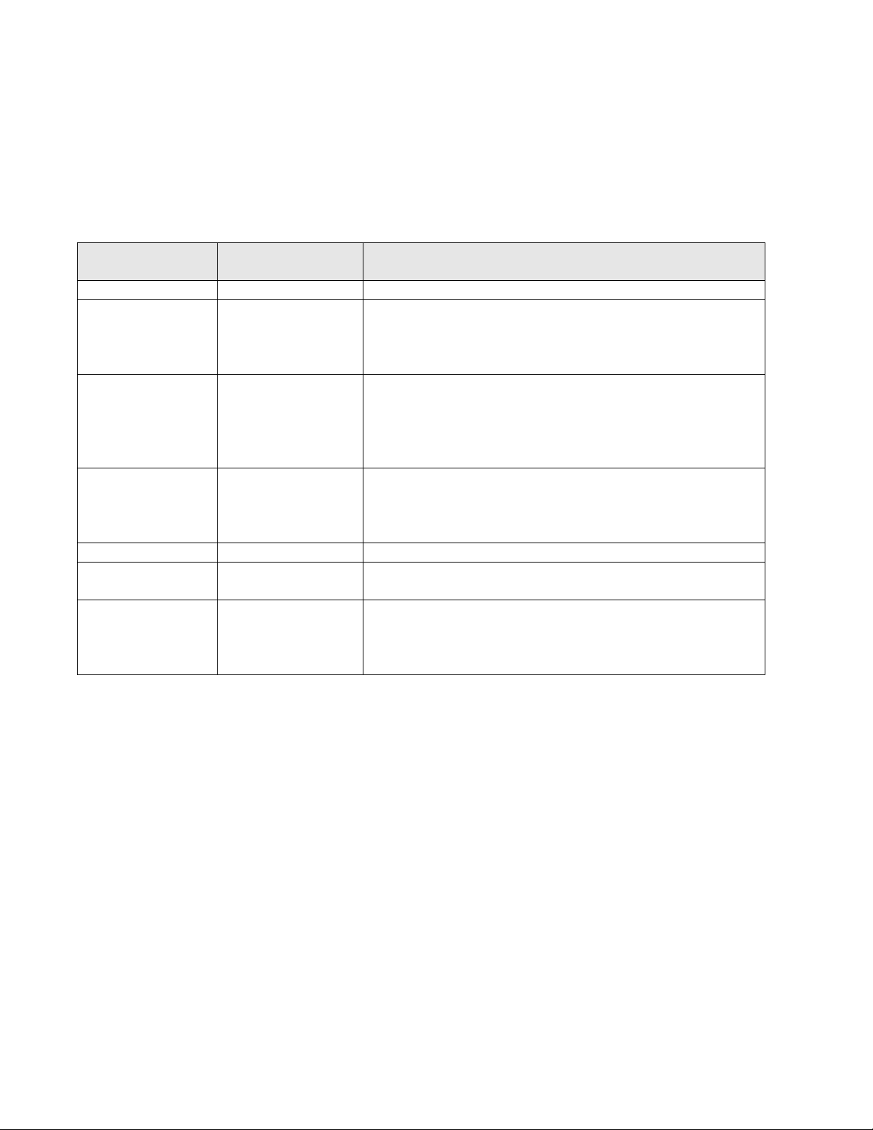
Zone Controllers Available Models & Features:
iconics Part
Number
Control
Outputs
PIR Cover
VZ7260F5000W VZ7260F5500W VZ7260C5000W VZ7260C5500W
2 x Analog 0 to 10 VDC
1 x Auxiliary reheat
contact
PIR cover ready. PIR cover factory installed PIR cover ready PIR cover factory installed
2 x Analog 0 to 10 VDC
1 x Auxiliary reheat
contact
2 x Tri-state floating
1 x Auxiliary reheat
contact
2 x Tri-state floating
1 x Auxiliary reheat contact
Master Controllers Available Models & Features:
iconics Part
Number
Controlled
Equipment
Main Control
Outputs
Unique
Features
VZ7656R1000W VZ7656H1000W VZ7656F1000W VZ7656E1000W
Rooftop Unit Heat Pump Unit Rooftop Unit Rooftop Unit
2H / 2C 3H / 2C 0-10VDC Analog Heat / 2C 2H / 2C
- Reversing
Valve Output
-
- 0-10VDC Analog Heat
Output
- Minimum Supply Air
Temperature Control
- 0-10VDC Fresh Air Damper Output
- 0-5VDC Airflow Sensor Input
- CO2 Level Control Sequence
- Free Cooling Economizer Sequence
4
Page 5
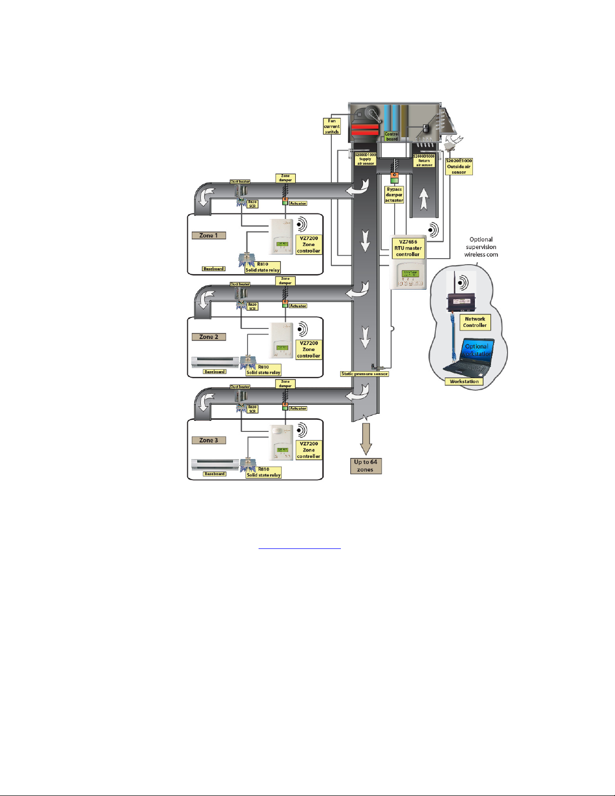
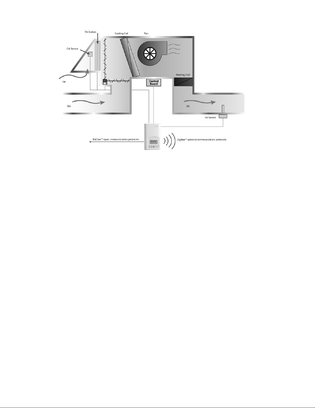
Wireless System Overview
Viconics VZ72605x00W zone controllers are used in conjunction with the VZ7656X1000W roof top
controller controllers. When combined, they operate typical single or multistage RTUs and their
associated local zones. The system operates the same as in the BACnet MS-TP wired version, but
operate using ZigBee/IEEE 802.15.4 physical layer for the communication bus.
Typical Wireless zoning system installation
Please refer to the following Viconics documents for detailed information and design guidelines for the wireless zoning system version:
The following documents are available at: www.viconics.com
• For detailed information on the Viconics VZ72xx zone controller, please refer and read the VZ72xx Product Guide. Installation and
commissioning information is available on document: LIT-VZ7260_W-Exx
• For detailed information on the Viconics VZ76xx RTU controller, please refer and read the VZ76xx Product Guide. Installation and
commissioning information is available on document: LIT-VZ7656_W-Exx
• PIR cover installation information is available on document: PIR Cover Installation-Exx
• Information on Wireless integration is available in the following documents: MAN_Wireless Stat Driver Guide-Exx & ITG-VWG-
50-BAC-Exx.
The system can be used in fully stand-alone mode or in communication mode with the Viconics VWG /
Jace-Driver set to expose the controller(s) objects externally.
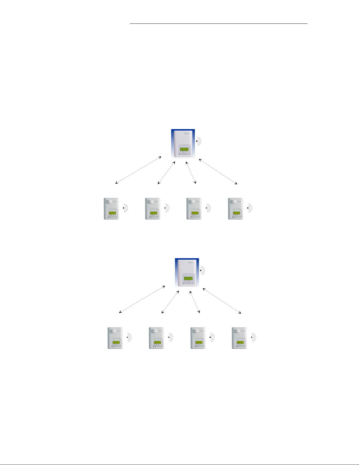
(SA) Stand-Alone applications: Where zoning system(s) are self sufficient for communication and no
external communication is required. In this configuration, the VZ76xx RTU controller acts as the network
coordinator. (More than one can be installed in a typical building application).
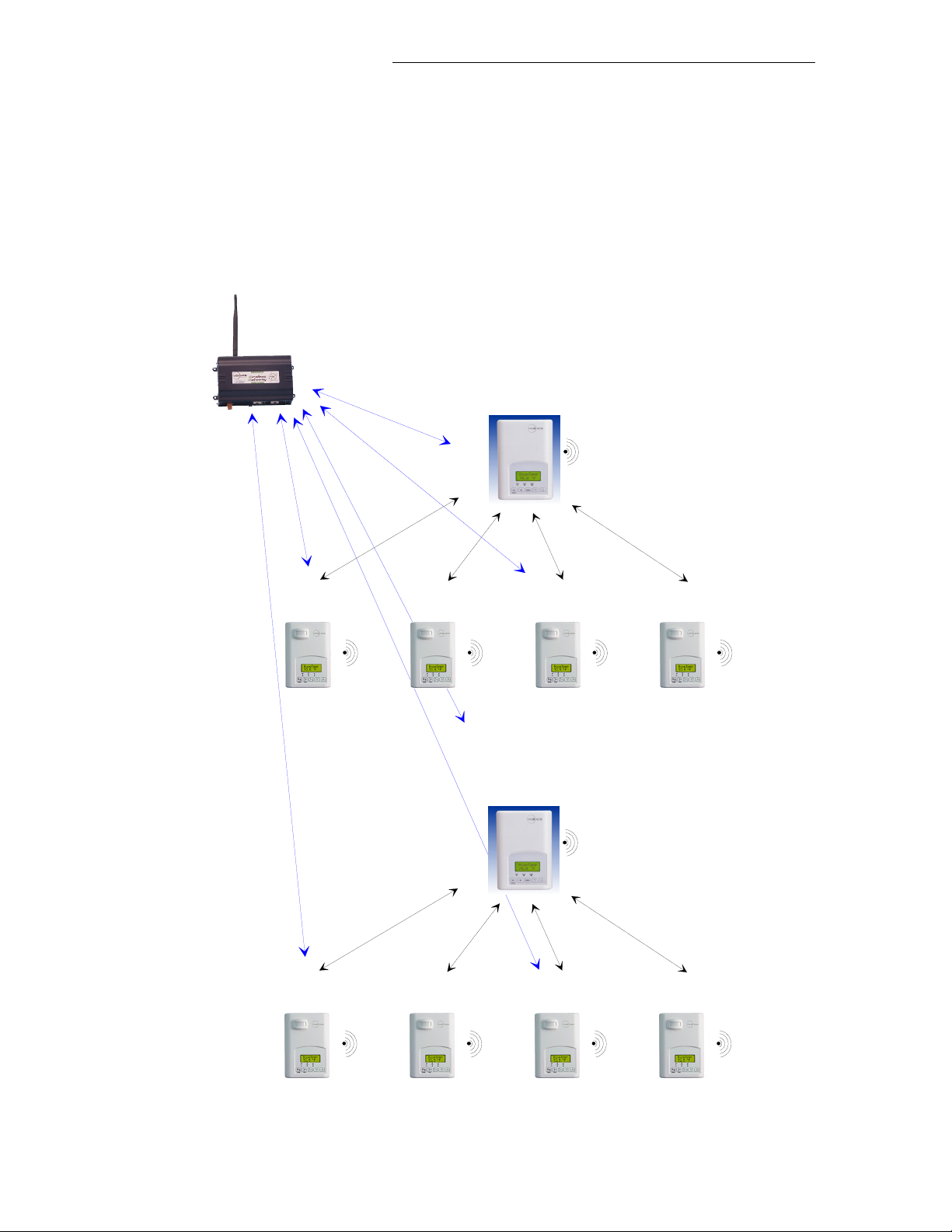
(NS) Networked Systems: Where zoning system(s) are required to communication with the Viconics
VWG and Jace-Driver set. In this configuration, the Viconics VWG and Jace-driver acts as the network
coordinator. (More than one can be installed in a typical building application).
5
Page 6
1A) Initial Design Criteria Considerations
The scope of this document is not intended to be a resource or white paper on VAV zoning system design.
There are many good resources available on the subject of VAV zoning systems and their associated
advantages and disadvantages. Please consult these resources for further information on this subject.
It is the responsibility of the designer and installer to ensure the following considerations are met:
• Size the installed equipment for properly calculated heating and or cooling peak loads. There are no
advantages to over sizing the system’s capacity to more than what is required as this simply leads to
short cycling of the equipment during small load periods.
• Properly size and layout all ductworks including the by-pass damper according to local codes and
standards in effect.
• Properly size the capacity of the zones according to the actual requirements of the room. Using
square footage calculations only can create situations where the installed total deliverable load may
be insufficient for the actual intended use of an area. Conference rooms, computer rooms, cafeterias
or other rooms where large gatherings occur would be a prime example of this scenario.
It is not the mandate of the zoning control system to correct for wrong initial mechanical layout and or load
calculations of the mechanical equipment. The control system will attempt to deliver the loads required by
master demanding zones by distributing the total available capacity of the installed equipment to the
required demanding areas. If the equipment is undersized for the required peak loads, the control system
will distribute the available capacity according to the priorities requested hence making most of the areas
comfortable.
Proper planning and design will always result in a job site being up and running faster with less service
calls during the initial occupancy period.
1B) Scalability and Limitations
The system is fully scalable in terms of number of Zone controllers and RTU controllers used on the same network layer (BACnet MS-TP or Wireless models).
Wireless controller systems overview:
(SA) Stand-Alone systems. There are no supervisory devices installed in this configuration.
In this application, the VZ76xx controller(s) are the network coordinators to their own system. I.E. they are
the network masters for each VZ72xx controller reporting to them. Each VZ76xx RTU controller and it’s
associated VZ72xx zone controllers use the same PAN ID and channel. The range of PAN ID on all
controllers to use is 251 to 500. This range is reserved for stand-alone (SA) system operation.
Smallest System Supported Largest System Supported
Single network of 127 nodes maximum
Number of Zones Number of RTUs Number of Zones Number of RTUs
1 ZN reporting to 1 RTU Minimum 63 ZN reporting to 1 RTU Minimum
There are no supervisory devices installed in this configuration. The system fully operates in stand-alone
mode.
6
Page 7
(NS) Networked Systems operation. There is a high-level supervisory device installed and used in this configuration.
In this application, a Viconics VWG and Jace-driver are the network coordinators for all controllers associated to the system and reporting their data point values.
Each VZ76xx RTU controller and its associated VZ72xx zone controllers will use the same PAN ID and
channel as the Viconics VWG and Jace-driver. The range of PAN ID on all controllers to use is 1 to 250.
This range is reserved for the networked system (NS) operation.
Smallest System Supported Largest System Supported
Single Network trunk of 128 nodes maximum
63 ZN reporting to 63 RTU Maximum
Number of Zones Number of RTUs Number of Zones Number of RTUs
1 ZN reporting to 1 RTU Minimum 126 ZN reporting to 1 RTU Minimum
In this configuration, there is a supervision device installed. The system will still fully operate in stand-alone
®
mode, but allows for a remote access to controller objects. It is seamlessly integrated into Niagara AX
Workbench environment with the use of the Viconics JACE communication device and its associated
driver.
Some added functions include:
- Detailed system graphics referred to as GUI’s which stands for Graphic User Interfaces
- Capacity to run remote trends, logs and diagnostics
- Capacity to use remote alarms for system events such as failures or maintenance
- Advanced and centralized energy management functions
- Remote scheduling
- Global outdoor temperature for all controllers
-
1C) Local Zone with Terminal Reheat or without Terminal Reheat
Including or excluding use of terminal reheat is dictated by design criteria’s of the installer. The use of
terminal reheat in a VAV system will always result in a more comfortable set-up for the occupants of the
space. However this may not be practical from a cost standpoint or regional requirements. System designs
will vary from Northern to Southern and Eastern to Western geographical locations because of the specific
regions peak load requirements.
In colder climates, VAV system heating operation without the use of terminal reheat typically always results
in colder outside walls. Although the zone dry-bulb temperature may be well maintained, it may be possible
for occupants not to be comfortable simply because of the low outside wall temperate.
Also, in the perimeter zones, the delivery process of the heating capacity from the ceiling is not as efficient
as when delivering the heating load directly where the losses occur such as in the case of a perimeter
electric baseboard or perimeter hydronic baseboard.
In regions where the heating load is small and required for only a small portion of the year, a properly sized
up zone VAV can deliverer the required heating demand and insure comfort without the use or terminal
reheat. However it is important to design the zone ductwork and area diffusers to be the most efficient with
air delivery close to the outside walls.
In certain problematic cases where air delivery may be an issue, the use of fan powered VAV units may
reduce the occupant discomfort by providing constant airflow to the zone and maximizing the air delivery
process.
7
Page 8
1D) Special Considerations
A typical office installation may require that a single unit service areas being used for different applications.
These areas will commonly be a combination of external and internal zones.
It is always good to verify the intended use of all areas knowing their true peak loads before committing to
its final design and sizing.
It may be necessary to oversize or undersize the design to meet their daily demands. The following are
examples of when over sizing of a zone damper may be needed:
• Areas with oversized windows that are exposed to the sun longer
• Conference rooms
• Cafeterias
• Areas with vending machines
• Areas with extra lighting
• Areas with computers, photocopier, etc…..
Areas such as computer rooms, kitchens and certain types of conference rooms may warrant a totally
separate system of their own and should not be part of the zones attached to an RTU. Certain critical areas
may call for cooling all year long and based on system settings could only guarantee occupant comfort a
portion of the year.
Knowing the critical areas of a building in advance and designing for them specifically will always result in a
more comfortable occupant. And it can be as simple as adding terminal reheat, radiant floor heating, a fan
powered VAV or even a separate small water source heat pump to critical area.
1E) By-Pass Damper Design Rules
A bypass damper is an airflow regulating device connected between the supply and return ducts. The
bypass damper will automatically open and bypass supply air normally delivered to the zone directly from
the supply to the return on a pressure rise when the VAV zone dampers are closing.
The by-pass damper should be sized to allow at least 70 to 80% of the nominal airflow of the RTU. A
simple way to determine if it is sized properly, assume all VAV zones are closed to their minimum position.
The by-pass should be large enough to re-circulate all the air from the RTU minus the amount set by the
minimum positions at the zones. A properly sized damper will result in an efficient and quiet operation.
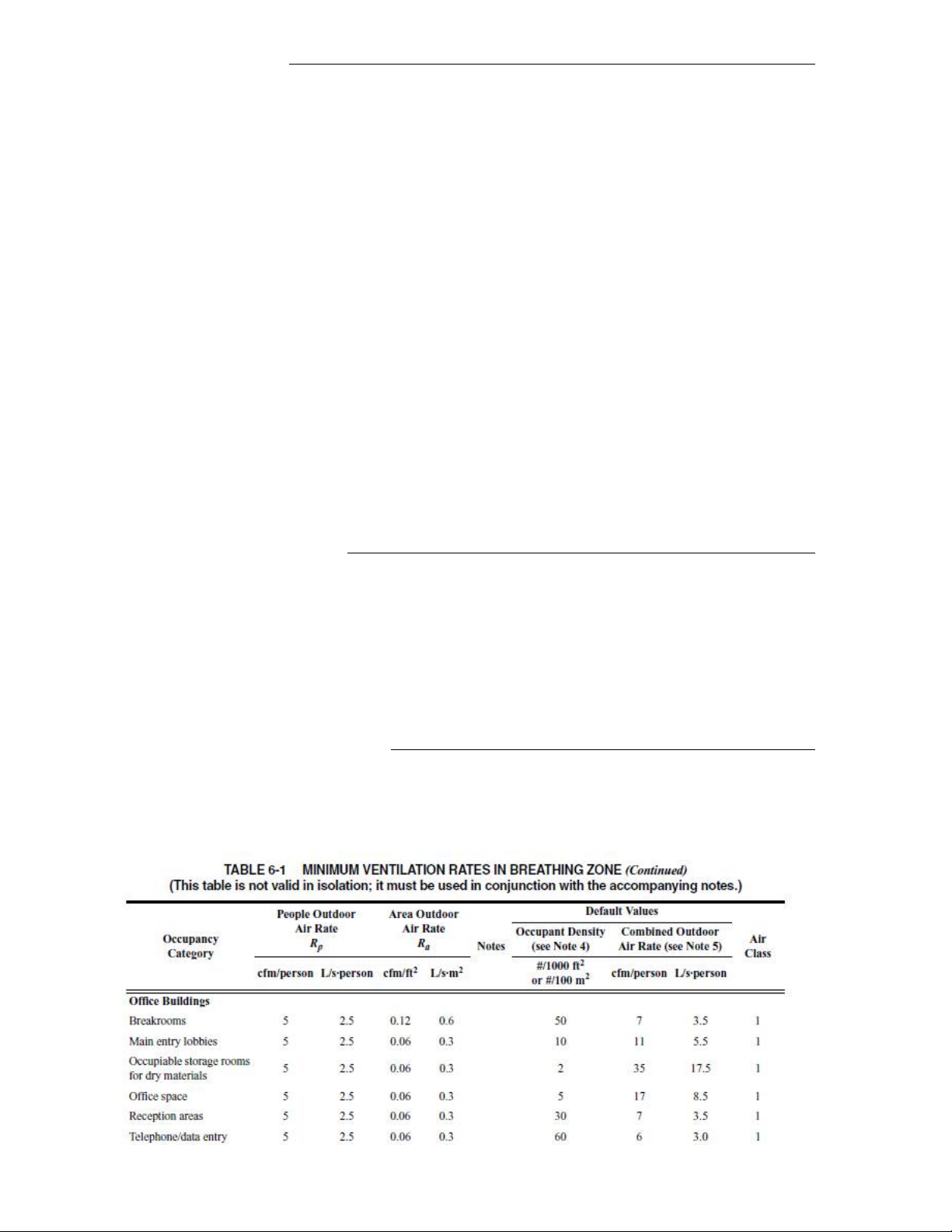
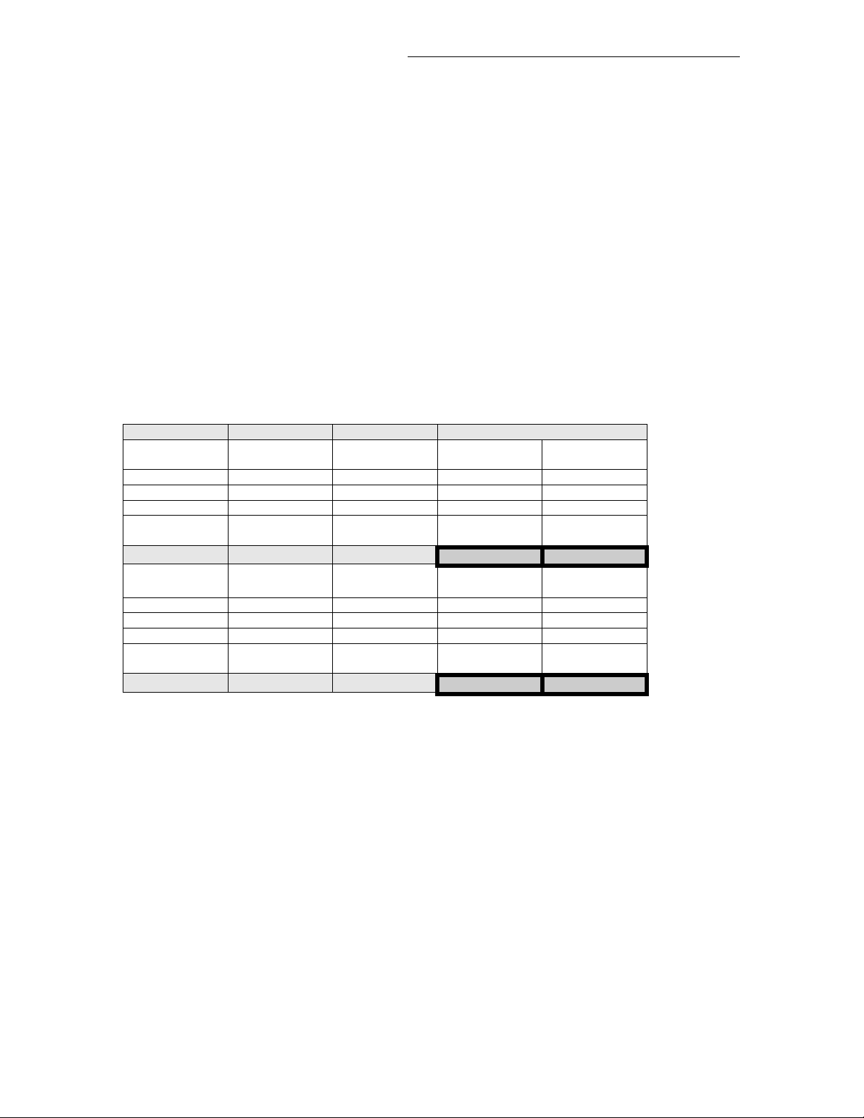
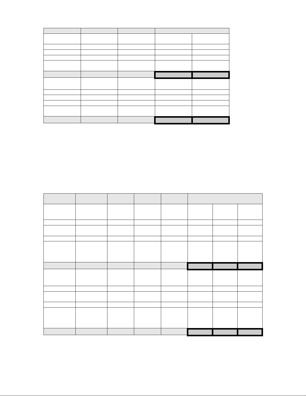
1F) Indoor Air Quality Control Standards
The IAQ control is achieved by the VZ7656E1000B controller through CO2 level and minimum fresh air
control. The building CO2 level has to respect the local building codes. The recommended outdoor air flow
per the ASHRAE standard for office buildings (Air class 1) is as follows:
Table from: ASHRAE Standard 62.
8
Page 9

2) Zone Controllers VZ7260X5x00W Operation
The following information needs to be carefully read and properly understood if proper system
commissioning is to be achieved.
Contrary to low end commercial and residential zoning controllers which use a two positions open-close
actuator, Viconics VZ7260X5x00X uses proportional analog 0 to 10 VDC modulating damper actuator. This
enables performances and control sequences to be much closer to what is normally found in DDC
application specific control devices.
The operation of the zone controllers is intrinsically linked with the operation of their RTU controller.
Although it will operate in a stand-alone mode if the communication network is down, normal operation of
the system as a whole requires that communication with the RTU controller is functional.
Data exchanged from the zone controllers to the RTU controller:
• Current PI heating demand ( output value is based on PI heating weight configuration )
• Current PI cooling demand ( output value is based on PI cooling weight configuration )
Data exchanged from the RTU controller to the zone controllers:
• Current central system occupancy
• Current system mode active ( hot air or cold air being delivered )
• Outdoor air temperature
9
Page 10
V
2A) Demand Based Heating and Cooling System
System operation as a whole consists of selecting which zone controllers will have heating and cooling
weighted votes used by the RTU controller to which they are attached. The weighted heating and cooling
demand values from the selected master zones are then used by the RTU controller to determine if heating
or cooling action is required for the system as a whole.
Both internal and external zones are typically serviced by the same unit. This means that the system may
be exposed to conflicting heating and cooling demands in mid-seasons. The conflicting demand conditions
are addressed with the heating and cooling lockouts based on the outside air temperature value at the
RTU.
The heating or cooling action at the zone is dependent on how the RTU controller treats and calculates
what will be delivered point in time to the zones. Many factors can influence the delivery or availability of
hot air or cold air to satisfy the current zone demand point in time.
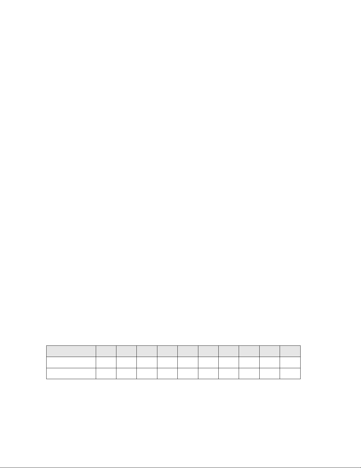
The following is an example of a RTU system mode calculation based on highest, average of the three
highest demands or the average of the five highest demands.
• RTU system mode calculations based on, average of the three highest demands or average of
the five highest demands.
•
Example 1 with 3 voting master zones only
oting Zone 1 Voting Zone 2 Voting Zone 3 RTU Control Type
Current heat
demand
50% 0% 0%
Heat weight set Heat weight set Heat weight set
50% 100% 100%
Resulting heat
weight to RTU
25% 0% 0% 25% 8.3%
Current cool
demand
0% 100% 100%
Cool weight set Cool weight set Cool weight set
100% 100% 50%
Resulting cool
weight to RTU
0% 100% 50% 100% 50%
Current heat
demand
Resulting heat
weight to RTU
Current cool
demand
Resulting cool
weight to RTU
Current heat
demand
Resulting heat
weight to RTU
Current cool
demand
Resulting cool
weight to RTU
Highest Average of 3
highest
It can be seen here that the resulting demand used by the RTU controller for the three master voting
zones are different and will result in different heating and cooling actions simply based on the RTU
configuration.
10
Page 11
V
V
V
V
V
V
Example 2 with 3 voting master zones only
oting Zone 1 Voting Zone 2 Voting Zone 3 RTU Control Type
Current heat
demand
100% 0% 0%
Heat weight set Heat weight set Heat weight set
100% 100% 100%
Resulting heat
weight to RTU
100% 0% 0% 100% 33.3%
Current cool
demand
0% 100% 100%
Cool weight set Cool weight set Cool weight set
100% 75% 75%
Resulting cool
weight to RTU
0% 75% 75% 75% 50%
Current heat
demand
Resulting heat
weight to RTU
Current cool
demand
Resulting cool
weight to RTU
Current heat
demand
Resulting heat
weight to RTU
Current cool
demand
Resulting cool
weight to RTU
Highest Average of 3
highest
It can be seen here that the resulting demand used by the RTU controller for the three master voting
zones are different and will result in different heating and cooling action simply based on the RTU
configuration.
• If the RTU is set to Control Type = Highest demand, the current action delivered by the RTU
will be heating.
• If the RTU is set to Control Type = Average of 3 Highest demand, the current action
delivered by the RTU will be cooling.
Example 3 with 5 voting master zones only
oting
Zone 1
Current heat
demand
100% 0% 50%% 50% 0%
Heat weight
set
100% 100% 100% 50% 100%
Resulting
heat weight
to RTU
100% 0% 50% 25% 0% 100% 58.3% 35%
Current cool
demand
0% 100% 0% 0% 100%
Cool weight
set
100% 50% 50% 50% 75%
Resulting
cool weight
to RTU
0% 50% 0% 0% 75% 75% 41.7.3% 25%
oting
Zone 2
Current heat
demand
Heat weight
set
Resulting
heat weight
to RTU
Current cool
demand
Cool weight
set
Resulting
cool weight
to RTU
oting
Zone 3
Current
heat
demand
Heat
weight set
Resulting
heat
weight to
RTU
Current
cool
demand
Cool
weight set
Resulting
cool
weight to
RTU
oting
Zone 4
Current
heat
demand
Heat
weight set
Resulting
heat
weight to
RTU
Current
cool
demand
Cool
weight set
Resulting
cool
weight to
RTU
oting
Zone 5
Current
heat
demand
Heat
weight set
Resulting
heat
weight to
RTU
Current
cool
demand
Cool
weight set
Resulting
cool
weight to
RTU
RTU Control Type
Highest Average
of 3
highest
Average
of 5
highest
It can be seen here that the resulting demand used by the RTU controller for the five master voting
zones are different and will result in different heating action simply based on the RTU configuration.
Please note that the heating or cooling action delivered to the zones is also dependent on heating
and cooling lockout functions based on the outdoor and supply air temperature. Please see the next
section for more information.
11
Page 12
2B) Overrides and User Zone Interface Lockouts
Each zone controller can have a function locked out for the local user. This can prevent unwanted inputs to
the system as a whole when the zone controllers are installed in public areas or when certain local user
interface functions of the zone controllers are to be prevented.
Lock level is access through the lockout configuration parameter. Please set the appropriate level for each
individual zone in the system according to their requirements.
VZ72xx Controller Lockout Level Configuration Value 0 1 2 3
Local occupied setpoint access using the Up and Down arrow keys Yes Yes Yes No
Pressing the local override key will only command the local override function
Yes Yes No No
only, However the local heating and cooling demands are not sent to the RTU
controller and the central system will not restart.
Typically used only when perimeter reheat is used and re-started during an
override period.
Pressing the override key allows an override for this zone controller only.
Pressing the local override key will command the local override function and
Yes No No No
allow the local heating and cooling demands to be sent to the RTU controller.
This will have for effect of re-starting the central system and allow delivery of hot
or cold air based on the current local demand.
Pressing the override key allows an override for this zone controller only. All
other zones although being delivered hot or cold air will still be in unoccupied
mode and using their unoccupied setpoints.
Pressing local keys that have their function locked out will display a “keypad lock” message on the zone
controller display.
If a global override is required for the whole system and all zones return to occupied mode, then the
override needs to be enabled at the RTU controller itself. This can be accomplished by using the local user
menu at the RTU controller or configuring the extra digital input as a remote override button if the location
of the override button is required to be installed centrally.
2C) Zone Set point Limits
It cannot be stressed enough that you must take caution and properly explain to the user or tenants of the
building or system that a demand based heating or cooling system is designed to respond to actual local
demand of a number of selected zones. Even if the local demand cannot be meet by the central system.
For the following reason it is recommended to “limit” the set point adjustments of any zone controller that
have actual demand voting capacity at the RTU controller. It is also recommended to limit set points of all
zones even if they are not voting on central RTU demand.
This will prevent any local set point adjustments that may create heating or cooling locking conditions at the
RTU controller by having local set points that are not reachable. It also avoids any master voting controller
from having unreasonable authority over the zoning system.
Ex.: If a local user sets the current occupied set point to 62
°F, the PI weighted demand sent by this zone to
the RTU controller will always be at its maximum value.
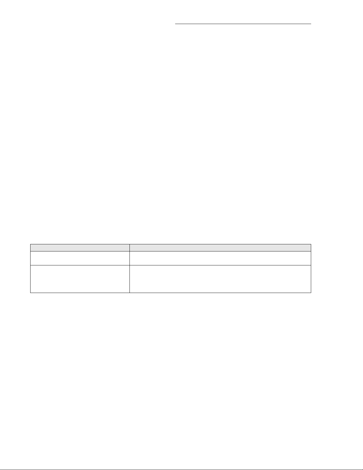
Configuration Parameter Factory Default Value Recommended Settings
Heat max
Default: 90 °F (32 °C) 75 °F (24 °C)
Maximum local heating setpoint limit
Cool min
Default: 54 °F (12 °C) 68 °F (20 °C)
Minimum local cooling setpoint limit
12
Page 13

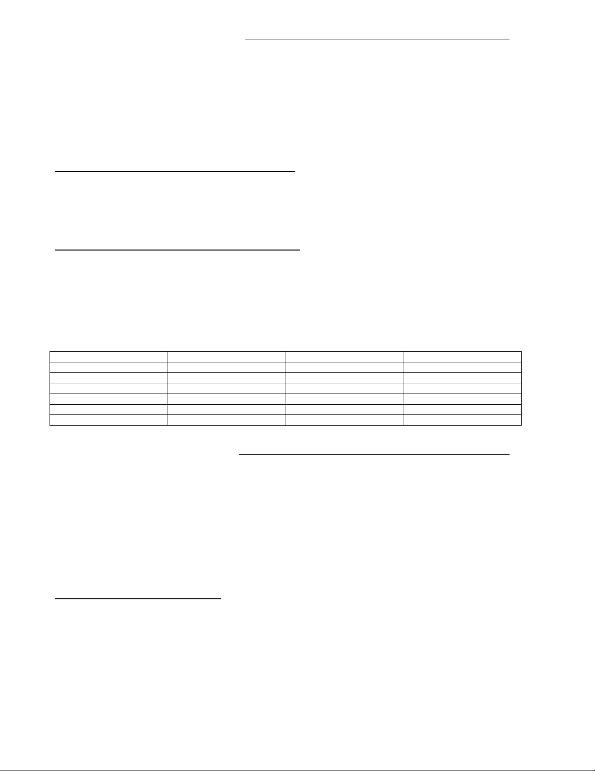
2D) Heating and Cooling Weight Zone Selection
For any system to properly operate, care must be taken to select which zones will be driving the system
and their weight attached to the calculations.
The values below are provided as an initial rule of thumb and need to be re-evaluated on a job per job
basis depending on the specifics of the system design and layout.
Total number of
zones
System layout
Recommended initial
number of master voting
zones with weight
1 to 5 All internal or external zones 1 to 3
3 to 5 Mix and match of internal and external zones 2 to 3
6 to 20 Mix and match of internal and external zones 3 to 8
21 + Mix and match of internal and external zones 8 +
Notes regarding the master voting zones selection:
o Not all zones in the system need to be masters. A good rule of thumb is to provide a ratio of 1/3 to
1/2 of the total number of zones which can be master to the system.
o On larger installations where internal zones are present in the system. I.E. zones not exposed to
an outside wall. The ratio of internal to external master zones should be in the approximate range
of 1 internal zone to 4 external zones.
o Zones selected to be masters for demand calculations should represent either:
- Typical zones or areas that will be exposed to some of the highest peak heating and
cooling loads.
- Zones or areas that represent a significant portion of the equipment peak load capacity.
Example, if a system has five zones where a single zone represents ½ of the total MAX
CFM of the equipment, then for sure this zone needs to be master to the system.
- Zones or areas that are subject to temporarily larger occupancy need to be part of demand
calculations if the zones are to be expected to respond during those spikes of occupancy.
Typical examples are: Conference room, cafeteria and other such common areas.
Attaching a zone as a master to the system which is either undersized or was commissioned with
operational flaws and errors may result in erratic system behaviour by adding total demand that cannot be
met by the system.
Notes regarding the weight parameter value of the master zones:
o Internal zones do not need to affect heating demand calculations. They should only affect the
cooling demand calculations. Such zones will always call for cooling during occupied periods even
during winter. If they where to call for heating at a certain point in time, then the surrounding
external zones would typically already be in heating mode.
- It is possible for an internal zone to be slightly overcooled during peak summer cooling
loads because of the dampers minimum position during occupied periods. The RTU is
providing its maximum cooling capacity and the amount of cold air provided by the
minimum position is already providing more capacity to the internal zone.
- Alternately, it is also possible for an internal zone to be slightly overheated during peak
winter heating loads because of the dampers minimum position. During occupied periods
the RTU is providing its maximum heating capacity and the amount of hot air provided by
the dampers minimum position will provide more heat to the internal zone than necessary.
13
Page 14

o External zones considered of primary importance should have both their heating and cooling
weight set to 100%
o Zones considered of secondary importance can have their weight set to a lesser value than 100%
to reflect their importance on the systems total voting when making demand calculations.
o Due to, their location, exposure, design, etc……, certain zones can have problematic behaviour
specifically in peak heating or cooling mode. (Ex.: when an office surrounded by panoramic
windows).
These zones can have their peak load demand satisfied. However this will be either at the expense
of energy used and or slightly overheating or overcooling the other zones.
It is the responsibility of the installer to properly identify any problematic areas and to determine if
those problematic areas are to be either fully satisfied or to simply leave them unsatisfied during
certain peak load periods in order to minimize energy consumption and to allow the rest of the
zones in the system to be optimized.
When dealing with the type of system which control many areas from a single central system, a
choice must be taken during set-up to either prioritize comfort or equipment cycling and energy
consumption.
- Adding many master voting zones (including problematic ones) to an RTU controller will
provide better comfort at the expense of higher energy consumption.
- Restricting the number of master voting zones (and excluding the problematic ones) to the
RTU controller will always provide a more energy efficient system at the expense of
comfort in certain areas.
2E) Minimum, Maximum and Heat flow Adjustments
Although system balancing can be accomplished by utilizing the controller’s built in configuration settings. It
is recommended to add a balancing side-takeoff damper on all zones. This will ensure that any
supplementary air can be reduced and will limit excessive noise due to airflow if the zones or associated
ductwork were improperly sized.
Minimum Position Adjustment (Min Pos)
This parameter sets the minimum amount of air being delivered to the zone. The VAV damper (when
powered) will never close below this value setting.
Maximum Position Adjustment (Max Pos)
This parameter sets the maximum amount of air being delivered to the zone; both in heating and cooling
mode. The VAV damper (when powered) will never open above this value setting.
Please note that the maximum amount of hot air delivered is set by this parameter, and NOT the Max Heat
flow parameter. Please refer to the next section for a description and usage of the Max Heat flow
parameter functions.
14
Page 15
Maximum Heatflow Adjustment (MaxHTPos)
Many installers will assume that this parameter sets the Maximum airflow of the VAV damper when the
RTU is delivering hot air. This is not the case. Both the maximum amount of cold AND hot air delivered to
the zone is set by the (Max Pos) zone damper parameter. Please see section above for more details.
The value set by this parameter will open the damper to a maximum heating position and will maximize hot
air flow when heat is requested with cold primary air using the duct reheat output.
The Max Heat flow function is only used if the local reheat configuration (RehtConf) is set to any value
except None. None = No local reheat. An example of this is a local reheat configuration using a duct
mounted reheat coil device.
Type of reheat
configured (RehtConf)
0 = None N/A Leave default of 30% or any adjustment. MaxHTPos is not used in scenario
1 = Analog Duct Rht
Only
2 = On/Off Duct Rht
Only
1= 10 seconds for Solid
3 = On/Off Peri Rht Only 0= 15 minutes Leave default of 30% or any adjustment. MaxHTPos is not used in scenario
1= 10 seconds for Solid
4 = Analog Duct Rht &
On/Off Peri Rht
BO5 reheat output time
base (BO5 Time
N/A Set to any value superior to the current selected minimum position. Ex. If the
0= 15 minutes Set to any value superior to the current selected minimum position. Ex. If the
state relays
state relays
Set to any value superior to the current selected minimum position. Ex. If the
MaxHTPos value function and adjustment
minimum airflow is set at 25% and Max heat is set at 75%.
If primary is cold air; when the PI heating loop (and analog output ) goes
from 0 to 100%, the damper linearly move from 25% to 75% opening
minimum airflow is set at 25% and Max heat is set at 75%.
If primary is cold air; when the BO5 output is energized on a call for heat, the
damper will directly move from 25% to a 75% position. As soon as BO5 is
de-energized, the damper will move back to 25% opening
Set to any value superior to the current selected minimum position. Ex. If the
minimum airflow is set at 25% and Max heat is set at 75%.
If primary is cold air; when the PI heating loop (and pulsed BO5 output )
goes from 0 to 100%, the damper linearly moves from 25% to 75% opening
Leave default of 30% or any adjustment. MaxHTPos is not used in scenario
minimum airflow is set at 25% and Max heat is set at 75%.
If primary is cold air; when the PI heating loop (and analog output ) goes
from 0 to 100%, the damper linearly moves from 25% to 75% opening
- The selected zone dampers minimum position has a direct impact on the temperature stability for
certain zones. Having a minimum position selected may produce an over cooling or over heating
effect. This effect is created when the primary air temperature is in the inverse mode than that
which the zone currently requires. An example of this is when an internal zone is requesting
cooling during winter while the RTU is supplying hot air for the external zones.
Adjusting the minimum position of a zone damper is mandatory by NA standards. It is however the
choice of the installer to decide if in some cases removing it or lowering it to a value below
standard may solves a system design issue. A good example of this would be an internal zone with
a grossly oversized VAV unit.
15
Page 16
How To Test and Balance the Minimum, Maximum and Heat Flow Values:
Balancing Minimum Air Flow
1. Be sure local system heating is allowed by setting the outdoor heating lockout value at the RTU
controller (H Lock)
2. Be sure the system is currently in heating mode. As viewed locally at the RTU controller by pressing
the manual scroll button and displaying the local Zone Sequence = Heat message prompt.
3. Be sure that the master voting zones are calling for heating by setting the appropriate set points
accordingly.
4. Set the currently balanced controller set point to its minimum value. An example of this would be
60F or when the set point is at least 7-8 F lower than the current room temperature. This will drive
the VAV zone to its minimum value.
5. Set the (Min Pos) configuration parameter to the desired value as required by balancing.
Balancing Maximum Air Flow
1. Be sure local system heating is allowed by setting the outdoor heating lockout value at the RTU
controller (H Lock)
2. Be sure the system is currently in heating mode. As viewed locally at the RTU controller by pressing
the manual scroll button and displaying the local Zone Sequence = Heat message prompt.
3. Be sure that the master voting zones are calling for heating by setting the appropriate set points
accordingly.
4. Set the currently balanced controller set point to its minimum value. An example of this would be 60F
or when the set point is at least 7-8 F lower than the current room temperature. This will drive the VAV
zone to its minimum value.
5. Set the (Max Pos) configuration parameter to the desired value as required by balancing.
Balancing Maximum Heat Flow
1. Be sure local system cooling is allowed by setting the outdoor cooling lockout value at the RTU
controller (C Lock).
2. Be sure local reheat is allowed by appropriately setting the outdoor reheat lockout value at the Zone
controller (AO2 OALK or BO5 OALK).
3. Be sure the system is currently in cooling mode. As viewed locally at the RTU controller by pressing
the manual scroll button and displaying the local Zone Sequence = Cool message prompt.
4. Be sure that the master voting zones are calling for cooling by setting the appropriate set points
accordingly.
5. Set the currently balanced controller set point to its minimum value. An example of this would be 60F
or when the set point is at least 7-8 F lower than the current room temperature. This will drive the VAV
zone to its minimum value.
6. Set the (MaxHTPos) configuration parameter to the desired value as required by balancing.
Please note that:
- 0 to 100 % is directly converted to 0 to 10 VDC on the VAV damper output. If the actuator has a
positioning input range of 2 to 10 VDC, then entering 50% minimum position is not directly
converted to 50% VAV damper position. Please refer to table below
VAV damper
position required
Setting for 0-10
VDC Actuator
Setting for 2-10
VDC Actuator
0% 10% 20% 30% 40% 50% 60% 70% 80% 100%
0% 10% 20% 30% 40% 50% 60% 70% 80% 100%
0 to
20%
28% 36% 44% 52% 60% 68% 76% 84% 100%
16
Page 17

- The damper position is never linear or proportional to airflow in a pressure dependent application.
Depending on how the zone damper was sized, a box may best slightly oversized, or slightly
undersized. In all cases, the PI loop (Proportional Integral) of the zone controller will always
compensate to find the proper required position to satisfy the current zone demand.
Air flow
Air flow
Undersized VAV
Effective
Effective
Control
Area
Control
Area
Oversized VAV
% opening
% opening
- Be sure the VAV actuator is properly installed and set-up so the VAV damper blade is able to
rotate from the fully opened, to fully closed position with no restriction to its mechanical rotation.
2F) Terminal Reheat Lockout
It is possible to lockout out the local terminal reheat function of the zones during hot seasons or when no
longer required. This prevents users from using the local reheat function simply based on a configured
outside air temperature value.
If RehtConf is set to AO2 OALK BO5 OALK
0 = None N/A, reheat not used N/A, reheat not used
1 = Analog Duct Reheat Only Set to desired value N/A BO5 not used by this reheat
sequence
2 = On/Off Duct Reheat Only N/A AO2 not used by this reheat
Set to desired value
sequence
3 = On/Off Perimeter Reheat Only N/A AO2 not used by this reheat
Set to desired value
sequence
4 = Analog Duct Reheat & On/Off
Perimeter Reheat
Set to desired value. Can be
different than BO5 OALK
Set to desired value. Can be
different than AO2 OALK
17
Page 18
2G) Passive Infra Red Motion Detector Cover (PIR)
The Viconics zone controllers are compatible with the new Viconics PIR (Passive Infra Red) cover
accessory. Controllers equipped with a PIR cover provide advanced active occupancy logic, which can
automatically switch occupancy levels from occupied to stand-by as required when local activity is detected
in the room.
This advanced occupancy functionality provides advantageous energy savings during occupied hours
without sacrificing occupant comfort. All zone controllers can be ordered with or without a factory installed
PIR cover.
This allows zones, which are infrequently occupied such as a conference room, storage areas or other
rooms to use relaxed set points during periods when there are no occupants present in the zone.
The advantage of using stand-by set points is to permit the system to recover fairly rapidly from stand-by to
occupied set points once movements are detected in a zone. The relaxed values of the stand-by setpoints
need to be far enough from occupied set points to optimise the energy savings a PIR cover can provide yet
close enough for the system to recover quickly and be within the occupants comfort zone in as short a time
as possible. If the span (Delta Temperature) from occupied to stand-by setpoints is too large, the zone will
not be able to recover quickly and the occupants will be left uncomfortable for the duration of the occupied
periods initiated by the PIR.
In order for the PIR logic function to be enabled, the following settings must be enabled at the zone
controller.
- If a local PIR cover is used, be sure to set the (
- If a remote PIR sensor is used on BI1, be sure to set the (BI1) parameter to Motion NO or Motion
NC
.
PIR Func) parameter to ON.
PIR logic
The PIR function is only used during occupied periods. If occupancy is desired during an unoccupied
period, simply press the local override button (if allowed by the local lockout level configuration). Then local
occupancy will toggle to Override (local occupied ) as per the ToccTimer time value for overrides.
Zone commanded occupied by the RTU schedule
Initial state when no movements
are detected by the PIR sensor
Initial movement detected by the
controller ( PIR cover or remote
PIR )
Stand-by
Occupied for 60 minutes after the last movement has been
detected. When the 60 minute timer value has expired and no new
movements have been detected, the controller will resume the
stand-by mode.
18
Page 19

2 H) AI4 CO2 / Other Sensor Input Operation
AI4 CO2 Sensor Input Operation
The VT76XXE controller features a 0-10VDC input (AI4) that is used for monitoring using any 0-10VDC
sensor or to control the building CO
level.
2
Using any 0-10VDC value for monitoring
If the AI4 input is used for monitoring purposes only (even if monitoring CO
parameter should be set to
None (not CO
2
).
with a CO2 sensor), the AI4
2
The value of the AI4 input can then be monitored at the network level (BACnet™ front end) under:
- AI4 value BACnet™ object (in VDC)
Locally at the controller, the value of AI4 can only be obtained by measuring the voltage between Scom
and AI4 using a voltmeter. The value of AI4, if AI4 parameter is set to
None, will not be displayed on the
controller’s screen at any time.
Using a 0-10VDC CO2 sensor for control purposes
If the AI4 input is used with a CO
CO
. In this case, a CO2 value will be displayed at the end of the configuration parameters list showing the
2
level measured by the sensor in ppm (particles per minute).
CO
2
sensor for control purposes, the AI4 parameter should be then set to
2
The value of the AI4 input will also be displayed at the network level under:
- Room CO
Value BACnet™ object (in ppm)
2
- AI4 value BACnet™ object (in VDC)
When AI4 parameter is configured to CO
VT76XXE will use these CO
values to determine the building’s CO2 Level for the IAQ control sequence.
2
, the CO
2
control is enabled only in Occupied mode. The
2
The following example shows the value of the BACnet™ objects as well as the values at the local
controllers based on the AI4 parameter setting and Occupancy status. The example uses a 0 – 2000ppm
sensor with a signal of 0-10VDC.
CO
2
AI4
parameter
None Occupied
CO2 Occupied
None Unoccupied
CO2 Unoccupied
Occupancy Sensor Voltage CO2 display at
local controller
5.0VDC No 0ppm 0ppm
5.0VDC Yes 1000ppm 1000ppm
5.0VDC No 0ppm 0ppm
5.0VDC Yes 1000ppm 0ppm
Room CO2
Value
Transferred
CO2 value
19
Page 20
2 I) Disable Minimum Position parameter
The VZ7260 zone controllers feature the DisMinPo (Disable Minimum Position) parameter that is used to
enable/disable the minimum damper’s minimum position parameter setting if the zone sequence (heat/cool)
is different than the controller’s demand (heat/cool).
The goal of this parameter is to prevent overcooling or overheating of zones that have demands that differ
from the general zone sequence due to the airflow through the damper opening (at the minimum position).
Most often, the zones affected are the internal zones (not on perimeter) whose demands are ignored by the
rooftop controller because they are not master zones (when it comes to cooling and heating weights).
Here are examples showing how the DisMinPo parameter setting affects the airflow.
DisMinPo set to Enable (minimum position enabled)
Minimum Position parameter:
Zone Sequence:
Zone Demand:
Cool (cool supply air)
Heat
15%
Damper Position: 15%
DisMinPo set to Disable (minimum position disabled)
Minimum Position parameter:
Zone Sequence:
Zone Demand:
Cool (cool supply air)
Heat
15%
Damper Position: 0%
IMPORTANT: The DisMinPo parameter is only effective when the Zone Sequence and the zone demand
are different, here’s the table showing when this parameter is effective.
Zone Sequence Zone Demand DisMinPo effectiveness Damper Position
Cool Cool Effective Minimum Position
Cool Heat Not Effective Closed
Cool No Demand Effective Minimum Position
Heat Cool Effective Minimum Position
Heat Heat Not Effective Closed
Heat No Demand Effective Minimum Position
2 J) Heating and Cooling Performances
The VZ7260 zone controllers also feature heating and cooling performance indexes that indicate the
performance of the zone controller in the last 90 minutes period (1.5 hours). The performances are
displayed at the end of the parameters list, as an average difference between the setpoint and the room
temperature for the last 90 minutes.
Example:
If the heating performance index HT Perf displays 0.5°F, it means that the average difference between the
heating setpoint and the room temperature for the last 90 minutes was 0.5°F.
Invalid Performance Indexes Values
The performance indexes will be unreliable (invalid) if one of the following happens:
- System mode is set to Off
- Zone demand change between heating and cooling
- Any setpoint change
- Occupancy status change
The invalid value will be displayed as a random value higher than 83.5°F (Imperial) or 46.0°C (Metric).
To have a valid performance value, the controller has to be stable (no above changed) for 90 minutes.
20
Page 21

3) RTU Controllers VZ7656X1000W Operation
The following information needs to be carefully read and properly understood if proper system
commissioning is to be achieved.
Unlike low end commercial or residential zoning controllers which typically only use two position demand or
non- demand logic to initialize heating and cooling functions, Viconics VZ7656X1000X uses local PI zone
demand(s) to operate heating and cooling stages. Accurate temperature control in the zones is achieved by
the time proportional control algorithm. This enables performances and control sequences much closer to
what is normally found in DDC application specific control devices.
The operation of the RTU controller is linked with the operation of the attached zone controllers. Although
the controller it will operate in a stand-alone mode if the communication network is down, normal operation
of the system as a whole requires that communication with the attached zone controllers is functional.
3A) Operation Data Exchanged
Independently of the network layer being BACnet MS-TP or Wireless, the flow of data exchanged between
the zones and the RTU controller can be summarized as follow:
Heating and cooling demand data is first exchanged from the ZN controllers to the RTU controller:
• Current PI heating demand ( output value is based on PI heating weight configuration )
• Current PI cooling demand ( output value is based on PI cooling weight configuration )
Each voting controller will also calculate is demand values based on their current occupancy mode and
setpoints currently in use: Unoccupied, Stand-By or Occupied.
Based on the control type configuration
(CntrlTyp), the RTU controller will calculate the resulting heating
and cooling zone demands. (See section 2A) Demand Based Heating and Cooling System.
Proper action to the heating or cooling stages using the time proportional control algorithm is accomplished
based on heating or cooling values.
- If resulting calculated PI heating demand > resulting calculated PI cooling demand, then ZN
sequence is heating
- If resulting calculated PI cooling demand > resulting calculated PI heating demand, then zone
sequence is cooling
- If resulting calculated PI cooling demand = resulting calculated PI heating demand, then zone
sequence stays in last current mode
21
Page 22

Many configuration and normal operation factors can limit action to the heating and cooling stages. Some
example of this would be:
- Heating or cooling lockout based on outdoor air temperature ( configuration )
- Heating or cooling lockout based on supply air temperature ( configuration )
- Heating or cooling lockout based on anti-cycling ( configuration or RTU control card )
- Fixed 2 minutes delay when RTU toggles from heating to cooling and vice-versa ( operation )
The RTU controller will then forward data to the zone controllers:
• Current central system occupancy
• Current zone sequence to use ( hot air or cold air being delivered )
• Outdoor air temperature
3B) Occupancy and Overrides
The occupancy of the zones is controlled by the schedule in the RTU controller.
- When this schedule output value is unoccupied (as shown on the RTU controller display), then the
attached zones will be unoccupied mode.
- When this schedule output value is occupied (as shown on the per RTU controller display), then
the attached zones will be either in occupied mode or stand-by mode if local PIR function is used.
It is possible to use remote scheduling though either BI1 or to use a remote time clock contact closure or a
wireless network occupancy command. This will disable the local schedule occupancy function to the
zones. The whole system and all attached zones can only be initiated at the RTU controller level. This is
done by using the local user menu at the RTU controller or by configuring the extra digital input (DI1) for a
remote override button if it is required to be installed centrally.
Any zone overrides will trigger the necessary heating or cooling action for the required zones only. All other
attached zones not requiring an override will remain in the unoccupied state.
3C) RTU interface Lockouts
RTU controller can have functions locked out for the local user. This can prevent unwanted inputs to the
system as a whole when the RTU controllers are installed in public areas or when certain local user
interface functions of the RTU controllers are to be prevented.
Lock level is access through the Lockout configuration parameter. Please set the appropriate level for each
individual zone in the system according to their requirements.
VZ76 Controller Lockout Level Configuration Value 0 1 2
Global override function through the user menu Yes Yes No
System mode access through the user menu Yes No No
Local schedule access through the user menu Yes No No
Local clock setting through the user menu Yes Yes Yes
22
Page 23

3D) RTU Heating and Cooling Supply Air Temperature Lockouts
One problematic aspect of any VAV zoning system is high demand for (heating or cooling) when most of
the zone VAV dampers are closed. This leads to most of the supply air being re-circulated through the
pressure by-pass and can lead to extremely hot or cold supply temperature.
- To prevent high supply temperatures (specifically with gas heating RTU), adjust discharge air
temperature high limit to required value.
Discharge air temperature high limit default value is:
80°F
Range is: 70°F to 150°F (21°C to 65°C) (increments: 0.5° or 5°)
- To prevent low supply temperatures (specifically to prevent freezing of RTU DX coils when a high
by-pass ratio is in effect ), adjust discharge air temperature low limit to required value.
Discharge air temperature low limit default value is:
55°F
Range is: 35 to 65°F (2.0°C to 19.0°C) (increments: 0.5° or 5°)
3E) RTU Heating and Cooling Outdoor Air Temperature Lockouts
H Lock and C Lock
- Parameter C Lock temperature disables the cooling stages based on the outdoor temperature.
- Parameter H Lock temperature disables the heating stages based on the outdoor temperature.
RTU mode lockouts need to be properly set to keep heating or cooling equipment cycling to a minimum. It
is the responsibility of the installer to decide if priority of the system will be given to comfort or not. The
adjustments for both lockouts will be different based on specific regions load requirements.
- A system located far north may require the RTU to deliver heating until a 75F outside air value is
attained due to the inertia of the building mass which will require heating during a cold night and
then will transition to a hot mid-season day.
- A southern system application may require the RTU to always deliver cooling and never lock up the
cooling mode while imposing strong restrictions on the heating side of the system.
Heating and cooling RTU equipment cycling will only happen within the overlapping dead band value left
between the H Lock and C Lock parameter adjustments. The tighter the value between these two
parameters, the less cycling will be encountered.
Heat Lock = 75F
Overlap = 10F
Cool Lock = 65F
Outside Air Temperature
It is also possible to set the system to completely eliminate heating and cooling equipment cycling based
on outdoor air limitations if this type of operation is required. This of will have an impact on specific zone
performances.
Heat Lock = 72F
No Overlap
Cool Lock = 72F
Outside Air Temperature
Heat Lock = 70F
No Heat
No Cool
5F deadband
Cool Lock = 75F
Outside Air Temperature
23
Page 24

3F) Critical Mid-Season Changeover
Heating and cooling RTU equipment cycling during mid-seasons is inevitable with a zoning VAV system if
any degree of comfort is to be maintained.
A properly setup system will be able to deliver comfort to conflicting zone demands during the mid-season
period by alternating heating and cooling at the RTU.
Normally, a lot of the unwanted heating and cooling switchovers can be eliminated by authorizing terminal
reheat or by limiting the RTU heating or cooling capacity throughput based on the outdoor temperature
Lock and C Lock )
temperature will have an impact on control performance of certain zones when the required heating or
cooling capacity is not available due to the lockout conditions.
Typically, the number of RTU heating or cooling switchovers cycles during conflicting demand situations
will be around the same as the RTU CPH settings
cooling).
Also, the recorded RTU supply delta temperature and demand variances will always be higher when using
a highest demand control type operation versus an average demand method. Energy consumption is also
expected to be higher with a highest demand control type operation versus an average demand method of
calculating the system requirements.
This will translate into two cooling and two heating cycle periods per hour.
. However, limiting the RTU heating or cooling throughput based on outdoor
(Default of 4 cycles per hour for both heating and
( H
3G) By-Pass Damper / VFD Control and Operation
The RTU controller has a built in static pressure control loop with an analog 0 to 10 VDC output that can be
configured to control a by-pass damper or a variable frequency drive (VFD). In order to operate, the static
pressure control loop needs to have a static pressure sensor connected to the static pressure input on the
RTU controller (terminal SP).
The type of pressure transducer used needs to be of voltage type (0 to 5 VDC) and have a 24 VAC halfbridge power supply.
The range of the pressure transducer needs to be one of the following and needs to be properly configured
using the static pressure configuration parameter (SP range).
Static pressure transducer range.
Voltage input range is 0 to 5 VDC.
- 0 = 0 to 1.5 in WC
- 1 = 0 to 2 in WC
- 2 = 0 to 3 in WC
- 3 = 0 to 4 in WC
- 4 = 0 to 5 in WC
Typically, the static pressure sensor probe is installed 2/3 of the way down the main ventilation duct.
The static pressure set point is set by the configuration parameter (Pressure). The default value is 0.8” WC.
The range and adjustability of the set point is: 0 to 2 in WC (0 Pa to 500 Pa) (increments: 0.1” WC or 25
Pa).
Please note that the static pressure scale will automatically change from inches of WC to PA (Pascals)
when the local units configuration parameter is changed.
0 = SI for Celsius / Pa pressure scale
-
- 1 = Imp for Fahrenheit / in. WC pressure scale
Operation of the static pressure control loop is dependent on the fan running or not, and the setting of the
pressure control type parameter SP Cntrl. For proper operation of the control loop, the static pressure
control actuator or VFD need to be properly installed.
24
Page 25

By-Pass Damper Operation:
- Control signal = 0 VDC = Static pressure by-pass damper fully closed = No air recirculation from
supply to return
- Control signal = 10 VDC = Static pressure by-pass damper fully opened = Maximum air
recirculation from supply to return
When the fan output is off (Terminal G), the static pressure control loop is off and the by-pass damper is
fully opened to 10 VDC output. This will minimize the air pressure related noise during initial fan start-up.
Please note that the fan is ALWAYS on during occupied periods and that it will cycle on demand with the
heating and cooling stages only during unoccupied periods.
When the fan output is on (Terminal G), the static pressure control loop is enabled and the by-pass damper
will modulate to maintain the desired static pressure set point according to the static pressure input reading
at the RTU controller. The current static pressure value can be read at the RTU controller at any time by
using the manual scroll function and displaying the pressure prompt.
Variable Frequency Drive Operation:
In this case the G fan output is used as an enable / disable output for the VFD.
The VFD should be configured to be reverse acting:
- Control signal = 0 VDC = VFD at high flow = Higher pressure.
- Control signal = 10 VDC = VFD at low flow = Lower pressure.
When the VFD is disabled (Terminal G is off), the static pressure control loop is off and the VFD output is at
0VDC. Please note that the fan is ALWAYS on during occupied periods and that it will cycle on demand
with the heating and cooling staged only during unoccupied periods.
When the VFD is enabled (Terminal G is on), the static pressure control loop is enabled and the VFD will
modulate to maintain the desired static pressure set point according to the static pressure input reading at
the RTU controller. The current static pressure value can be read at the RTU controller at any time by using
the manual scroll function and displaying the pressure prompt.
3H) Minimum Supply Heat Temperature Control and Lockout
The VZ7656F1000W master controller features a minimum supply air temperature PI control loop that is
used to prevent the supply air temperature from dropping below the Min SH (Minimum Supply Heat
Temperature) parameter value.
This control sequence is only available in the
An outdoor temperature supply air lockout is also one of the VZ7656F1000W features. This lockout only
affects the minimum supply heat control sequence. Room temperature control is not affected.
The SH Lock is the parameter used to set the outdoor air temperature above which the minimum supply
heat temperature control sequence is disabled.
Example 1:
Outdoor Temperature:
SH Lock:
Minimum Supply Heat Temperature Control is
60°F
55°F
VZ7656F1000W modulating heat rooftop controller.
disabled
Example 2:
Outdoor Temperature:
SH Lock:
Minimum Supply Heat Temperature Control is
55°F
50°F
enabled
25
Page 26

3I) Indoor Air Quality Control & Operation
The fresh air damper can be controlled through more than one sequence to achieve different control
strategies such as free cooling (economizer mode), minimum fresh air control and CO
level control. Here
2
are the control sequences available:
Note: For the sequences mentioned below, the following conditions must be met in order for the
sequences to be performed as stated:
- Max Pos parameter value must be greater than Min Pos Parameter value.
- Mac CO
- Max FA parameter value must be greater than Min FA Parameter value.
Economizer Control Mode Only
parameter value must be greater than Min CO2 Parameter value.
2
If the fresh air damper is to be used only for free cooling purposes (economizer mode, without fresh air
measurement station or CO
control), only the Min Pos parameter and the free cooling sequence will be
2
active.
The FA Range parameter should be set to 0 CFM. (Default Value = 0 CFM)
-
- Set the Chngstpt parameter to desired value which free cooling is enabled. (Default Value =
55°F)
If the outside air temperature is greater than the changeover setpoint, then normal mechanical cooling will
be used. If the outside air temperature is less than or equal to the changeover setpoint, then free cooling
will be enabled and mechanical cooling stages will be locked out.
26
Page 27
Economizer Mode and Fresh Air Measurement Station
If the fresh air damper is to be used for both free cooling and minimum fresh air volume control
(economizer mode and fresh air measurement station, but without CO
parameter and the free cooling sequence will be active.
level control), only the Min FA
2
- The FA Range parameter should be set to a value higher than 0 CFM (0 CFM disables the
fresh air control).
- Min FA (minimum fresh air) parameter should be set to the desired level.
The FA Range parameter value should be set to the maximum capacity of the fresh air measurement
station. Therefore the relationship between air volumes and input signals can be established. For example,
if the fresh air station capacity is 10000 CFM, set FA Range to 10000.
This will set the relationship of
0 VDC = 0 CFM and 10VDC = 10000 CFM.
27
Page 28

Economizer Mode and CO2 Level Control
If the fresh air damper is to be used for both free cooling and CO
level control, but without fresh air measurement station), only the Min Pos, Max Pos, Min CO2and Max CO2
parameters as well as the free cooling sequence will be active.
The FA Range parameter should be set to 0 CFM.
-
- Set AI4 parameter to CO
- Min Pos, Max Pos, Min CO
(0 VDC = 0ppm ; 10VDC = 2000ppm)
2
and Max CO2 parameters should be set according to the required
2
setting.
level control (economizer mode and CO
2
2
Max Pos
Current
Fresh Air
Damper
Position
Min Pos
Min CO
Max CO
Current
2
Level
CO
2
2
The higher value between free cooling output and interpolation output between the above graphic
will be the signal sent to the fresh air damper.
28
Page 29

p
Economizer Mode, CO2 Level Control and Fresh Air Measurement Station
If the fresh air damper is to be used for both free cooling and CO
measurement station, only the Min FA, Max FA, Min CO
and Max CO2 parameters as well as the free
2
cooling sequence will be active.
The FA Range parameter should be set to something other than 0 CFM.
-
- Use an air flow transmitter to read fresh air level with AI2 input (0-5 VDC input)
- Min FA, Max FA, Min CO
setting.
and Max CO2 parameters should be set according to the required
2
level control with a fresh air
2
Max FA
Setpoint
Current
Fresh Air
oint
Set
Min FA
Setpoint
Max CO
Min CO
2
Current
Level
CO
2
2
The higher value between free cooling output and interpolation output based on the above graphic will be
the signal sent to the fresh air damper. If the occupancy is unoccupied, then the CO
0%.
control output will be
2
29
Page 30

4) Wireless Communication Overview
The Viconics VZ7260X5x00W and VZ7656X1000W controllers, Viconics Wireless Gateway (VWG) and
Jace-driver and other related wireless controller family (VT7xxxXxxxxW) networkable devices operate
using ZigBee/IEEE 802.15.4 physical layer for communication.
General characteristics of the wireless physical communication layer are:
· Wireless physical layer of 2.4GHz with a data rates of 250 kbps
· Yields high throughput and low latency
· Automatic multiple topologies configuration: star, peer-to-peer, mesh
· Fully handshake protocol for transfer reliability
· Range: 30 feet / 10M typical (up to 100 feet / 30 M based on environment)
IEEE 802.15.4 along with ZigBee’s Network and Application Support Layer provide:
· Low cost installation deployment
· Ease of implementation
· Reliable data transfer
· Short range operation
· Very low power consumption
· Appropriate levels of security
The main network coordinator for the wireless the IEEE 802.15.4/ZigBee network can be either:
• The VZ76xx RTU controller for
sufficient for communication and no external communication is required. In this layout, the VZ76xx RTU
controller acts as the network coordinator.
• The Viconics Wireless Gateway (VWG / Jace-Driver for
zoning system(s) (more than one can be installed in a typical building application) are required to
communicate with the Viconics VWG / Jace-Driver set. In this layout, the Viconics VWG / Jace-Driver
acts as the network coordinator.
Many network specific features of the IEEE 802.15.4 standard are not covered in detail in this paper.
However, these are necessary for the efficient operation of a ZigBee network. The features of the network
physical layer include receiver energy detection, link quality indication and clear channel assessment. Both
contention-based and contention-free channel access methods are supported with a maximum packet size
of 128 bytes, which includes a variable payload up to 104 bytes. Also employed are 64-bit IEEE and 16-bit
short addressing, supporting over 65,000 nodes per network. All the properties of the physical layer are
used and employed by the Viconics mesh network but are hidden to the user for ease of configuration and
commissioning of the network database.
(SA) Stand-Alone applications: Where zoning system(s) are self
(NS) Networked Systems applications: Where
30
Page 31
4A) (SA) Stand-Alone applications
When PAN ID is used with a range of 251 to 500, for (SA) Stand-Alone Systems.
In this application, the VZ76xx controller(s) act as the coordinators to their own system. I.E. they are the
network masters for each VZ72xx controller reporting to them when the whole zoning system(s) is self
sufficient and communication and no external communication is required.
• Wireless controller factory default Channel and PAN ID = Controller(s) offline
• VZ76xx RTU controller is the network coordinator
• Range of PAN ID on all controllers to use 251 to 500. This range is reserved for stand-alone system
operation
Examples:
System 1
RTU VZ76 Coordinator
Channel 25 ID
200
Zone VZ72 Router
Channel 25 ID
200
Zone VZ72 Router
Channel 25 ID
200
Zone VZ72 Rou ter
Channel 25 ID
200
Zone VZ72 Rou ter
Channel 25 ID
200
System 2
RTU VZ76 Coordinator
Channel 25 ID
205
Zone VZ72 Router
Channel 25 ID
205
Zone VZ72 Router
Channel 25 ID
205
Zone VZ72 Router
Channel 25 ID
205
Zone VZ72 Rou ter
Channel 25 ID
205
Notes:
· Each system with a VZ76xx RTU master will use a unique PAN ID and or channel settings
31
Page 32
4B) (NS) Networked System applications
When PAN ID is used with a range of 1 to 250, for (NS) Networked Systems.
In this application, any controller(s) are simply routers to the system. The VWG and Jace-driver is the
coordinators to the system. The VWG and Jace-driver are the network masters for any controller(s)
reporting to them, where zoning system(s) are required to communicate and exchange data points with the
Viconics VWG and Jace-driver set. (More than one can be installed in a typical building application).
· Wireless controller factory default channel and PAN ID = Controller(s) offline
· VWG Jace-Driver is the network coordinator
· Any controllers (VZ72’s, VZ76xx RTU’s or any VT7xxx wireless controllers) act as routers.
· Range of PAN ID on all controllers to use 1 to 250. Reserved for networked system operation.
Examples:
Coordinator
Channel 25 ID
200
System 1
RTU VZ76 Router
Channel 25 ID
200
Zone VZ72 Router
Channel 25 ID
200
Zone VZ72 Router
Channel 25 ID
200
Zone VZ72 Router
Channel 25 ID
200
Zone VZ72 Router
Channel 25 ID
200
System 2
RTU VZ76 Router
Channel 25 ID
200
Zone VZ72 Router
Channel 25 ID
200
Zone VZ72 Router
Channel 25 ID
200
Zone VZ72 Router
Channel 25 ID
200
Zone VZ72 Router
Channel 25 ID
200
Note:
· Each controller(s) uses the same PAN ID and channel as VWG Jace-Driver coordinator.
VWG and Jace-driver supports network integration for required GUI and system status objects.
·
32
Page 33
4C) Basic Initial Design and Deployment Considerations
Proper design considerations need to be addressed prior to the installation of a Viconics wireless zoning
system.
1. To avoid network interference with 802.11 Wi-Fi devices in the 2.4GHz spectrum range, Viconics
recommends the use of 802.15.4 channels 15, 25 and 26 only. 802.11 Wi-Fi transmissions overlap and
may interfere with other channel selections allowed by 802.15.4 (Channels 11 to 14 & 16 to 24)
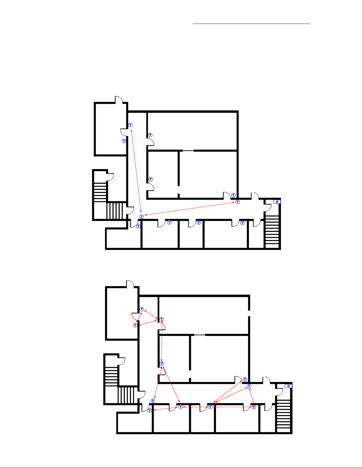
2. The maximum distance between each controller node should be 100 feet (30 M) or less between two
controller nodes. (Clear line of sight).
Open clear line of sight distance between
2 nodes should be a maximum of
100 feet ( 30 M )
• Non line of sight should be less than 50 feet (15M). Typical gypsum wall partitions
made with metal stud frame construction.
Non line of sight maximum distance
for typical gypsum wall partitions
should be maximum of 30 feet
between 2-thermostat nodes
( 10 M )
( 15 M )
33
Page 34
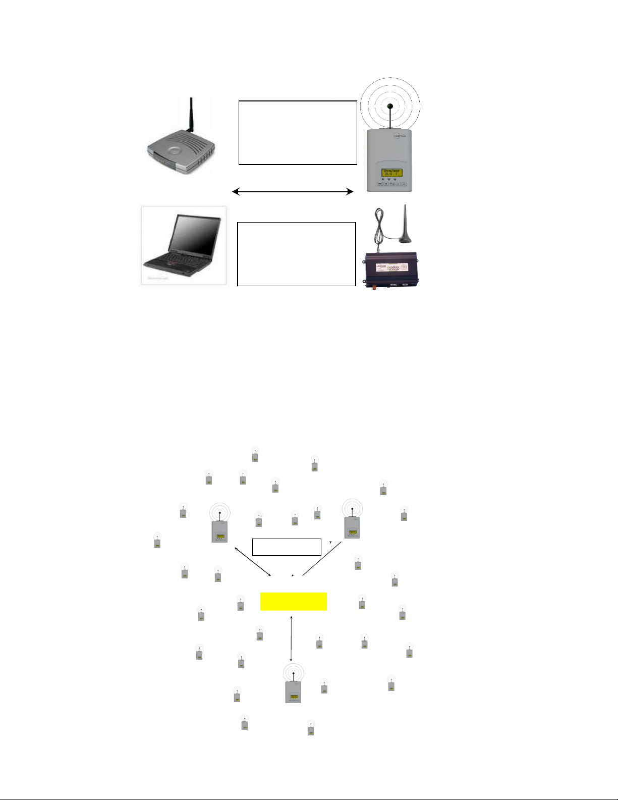
)
3. Ensure that the minimum distance between any Viconics node and any Wi-Fi devices (wireless routers,
wireless adapters, lap-tops using wireless networks, etc….) to be at least 3 feet (1 M) and preferably 10
feet (3 M) or more.
Minimum 3 feet (1 M)
between Wi-Fi
equipment and
Viconics wireless
Preferably 10 feet (3
M) or more between
Wi-Fi equipment and
Viconics wireless
4. Ensure that at least one controller is within 30 feet of the coordinator (VZ76xx for (SA) or VWG and
Jace-Driver for (NS)) for every cluster of 10 VZ72xx zone controllers installed.
5. When possible, always try to locate the coordinator (VZ76xx for (SA) or VWG and Jace-driver for (NS))
near the center of all associated VZ72xx zone controllers installed.
6. Always try to locate the coordinator (VZ76xx for (SA) or VWG and Jace-driver for (NS)) near or in the
line of sight to as many wireless controllers as possible.
7. Try to avoid metal, brick walls or concrete obstructions between wireless devices when possible.
8. For a 30 wireless controllers installation. A minimum of three of them should be within 30 feet or 9
Meters of the coordinator (VZ76xx for (SA) or VWG and Jace-Driver for (NS)) range.
30 feet (9 M
Coordinator
34
Page 35
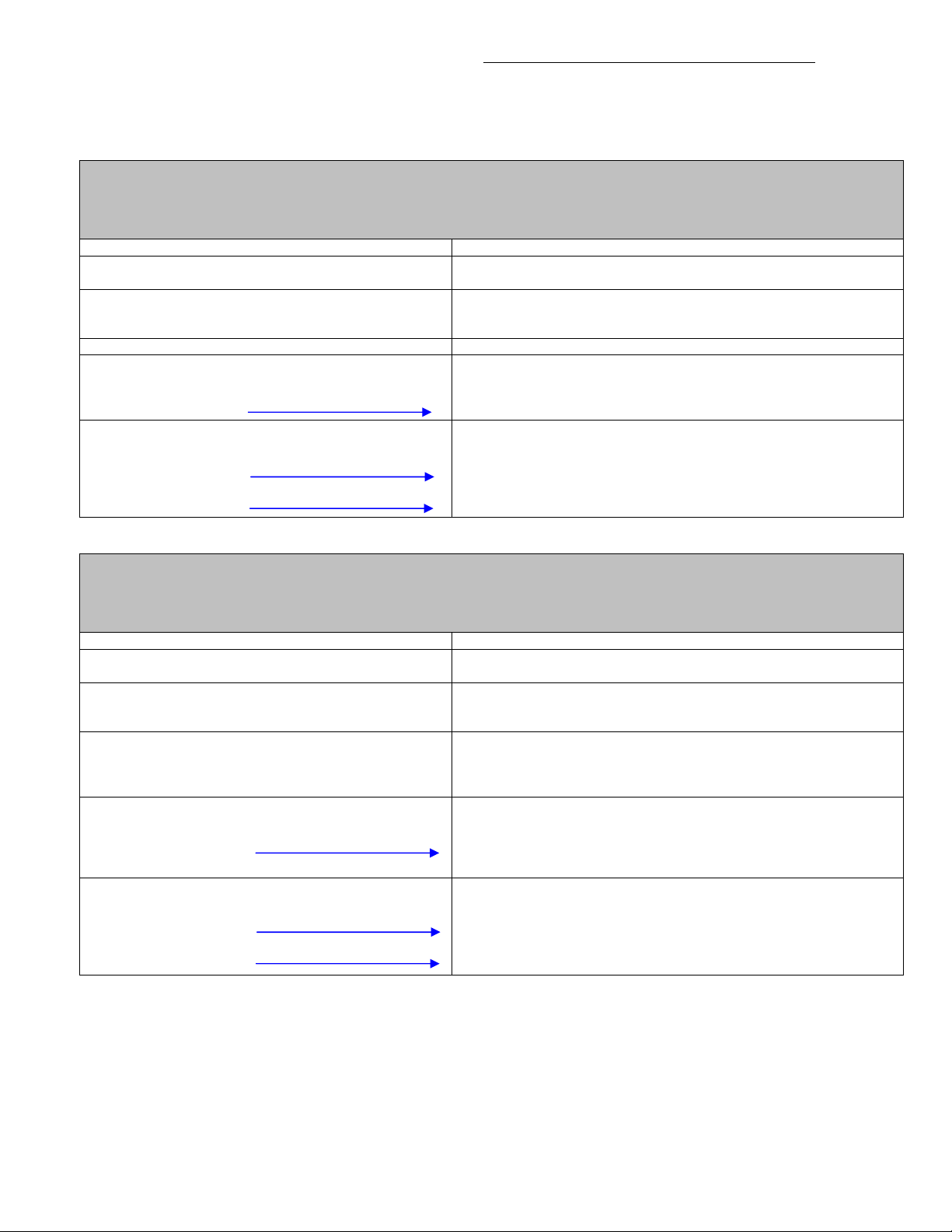
4D) Communication status LED and Troubleshooting
Each controller has a communication status service LED for troubleshooting purposes. Monitoring this LED
will determine the network condition for each individual device and will tell you if they are successfully
communicating with their peers on the network.
VZ76xx Adapter LED Status Indicators
(SA) Stand-Alone applications. When a PAN ID is used with a range of 1 to 250, for (SA) or Stand-Alone Systems
applications where the VZ76xx is used as a coordinator
1 x 200ms short blink
2 x 200ms short blinks
3 x 200ms short blinks
4 x 200ms short blinks
4 x 200ms short blinks
and
1 x 1500ms long blink
4 x 200ms short blinks
and
1 x 1500ms long blink
and
1 x 3000ms long blink
Power on
Power on
Communicating with controller base
Power on
Communicating with controller base
Valid Pan ID & Channel
Not Used
Power on
Card memory initialized properly
Communicating with controller
Wireless networks started successfully
Power on
Card memory initialized properly
Communicating with controller
Wireless networks started successfully
Wireless communication with VZ72 Zone controllers active
VZ76 Adapter LED Status Indicators
(NS) Networked System applications. When PAN ID is used with a range of 1 to 250, for (NS) or Networked
Systems applications where the VWG and Jace-Driver is used as a coordinator
1 x 200ms short blink
2 x 200ms short blinks
3 x 200ms short blinks
4 x 200ms short blinks
4 x 200ms short blinks
and
1 x 1500ms long blink
4 x 200ms short blinks
and
1 x 1500ms long blink
and
1 x 3000ms long blink
The long 3000ms status flag is simply enabled by VZ72xx zone controllers reporting PI demand value to
the VZ76 RTU controller. As long as a single VZ72xx zone controller is registered at the VZ76xx RTU, the
long 3000ms status flag will be enabled
If the long 3000ms status flag indicating communication with the VZ7xx wireless zones controller is
disabled after one minute; the ComLost alarm flag will be displayed at the VZ76xx RTU controller.
Power on
Power on
Communicating with controller base
Power on
Communicating with controller
There is connectivity to wireless network
Power on
Communicating with controller
There is connectivity to wireless network
VWG / Jace-Driver is communicating with Wireless controller
Power on
Communicating with controller
There is connectivity to wireless network
VWG / Jace-Driver is communicating with Wireless controller is also
added to the VWG / Jace-Drive database
Power on
Communicating with controller
There is connectivity to wireless network
VWG / Jace-Driver is communicating with Wireless controller is also
added to the VWG / Jace-Drive database
Wireless communication with VZ72 Zone controllers active
35
Page 36

VZ72 Adapter LED Status Indicators
1 x 200ms short blink
2 x 200ms short blinks
3 x 200ms short blinks
4 x 200ms short blinks
4 x 200ms short blinks
and
1 x 1500ms long blink
4 x 200ms short blinks
and
1 x 1500ms long blink
and
1 x 3000ms long blink
Power on
Power on
Communicating with controller base
Power on
Communicating with controller
There is connectivity to wireless network
Power on
Communicating with controller
There is connectivity to wireless network
VZ76 or VWG / Jace-Driver is communicating with Wireless controller
Power on
Communicating with controller
There is connectivity to wireless network
VWG / Jace-Driver is communicating with Wireless controller is also
added to the VWG / Jace-Drive database
Power on
Communicating with controller
There is connectivity to wireless network
VWG / Jace-Driver is communicating with Wireless controller is also
added to the VWG / Jace-Drive database
Wireless communication with VZ76 RTU controllers active
The 3000ms status flag is enabled when the VZ72xx zone controller successfully reads the required
functional data points from its attached master VZ76xx RTU controller: Occupancy, Outdoor temperature,
zone sequence, etc….
5) System Commissioning
If proper system operation is expected, then proper system commissioning should be done at all levels.
A zoning system has a huge dependency on the demand and response being fully functional both at the
RTU and the zone level.
5A) Proper Commissioning of the Zone Controllers
At the zone level, care should be taken to insure that the following criteria(s) are met:
- Proper sizing of the VAV zone damper and the design of the air distribution system to insure that
peak load demands can be meet when the RTU delivers the capacity.
- VAV Damper operation. Insure that the VAV damper blade can rotate completely without any
mechanical limits as those are set by the controller parameters.
- Make sure the DA/RA setting of the VAV actuator is not set reversed. If improperly set it will result
in a zone that can never be satisfied and a demand to the RTU that will always be present if the
zone is a master zone.
- Min, Max and HeatMax flow must be set during balancing. Also, adjustments may need to be done
to the main trunk side-take-off balancing damper if the local VAV trunk is equipped with one.
- Proper setup of the following important configuration parameters: Reheat lockouts, set point limits,
user interface lockout and demand weight adjustments to the RTU. All of these need to be properly
evaluated and set according to the specifics of the installation.
- Addressing of both the MAC zone numbers to a specific RTU controller needs to be planned prior
to the installation.
36
Page 37

t
d
d
5B) Proper Commissioning RTU Controllers
RTU level, care should be applied to insure the following conditions are met:
At the
- Proper sizing of the RTU heating and cooling capacity to insure it will meet the highest
instantaneous peak loads of the areas deserved by the system.
- Proper strategy and system layout of the mechanical system architecture.
- Proper commissioning and verification of the by-pass system. A wrongly configured by-pass
system may cause all the zones in a section of the system unable to get the proper RTU capacity
down to the zones. Even when all of the zones are properly commissioned and all equipment are
properly sized.
- Proper setup of the configuration parameters: Heating lockout, cooling lockout, control type
strategy, discharge air low and high limits, static pressure sensor range and static pressure
setpoint. All of these need to be properly evaluated and set according to the specifications of the
installation.
- Proper verification of RTU I/O operation including the RTU on board economizer operation.
5C) Operational System Checklist
It is recommended to keep a checklist of all milestones and configuration settings during start-up. This list
should be kept as a reference with the system when it is fully commissioned. The following is only provided
as a guideline template but can be extremely helpful for servicing issues and questions.
RTU Unit
Manufacturer: Serial number
Model number: Year of manufacture
Location: Date of original installation
Cooling tonnage: Cooling number of stages:
Heating capacity: Heating number of stages:
Maximum CFMs: Total number of zones:
RTU Configuration, critical operational configuration parameters are in bold
RTC MAC
RTC Baud
PAN ID
Channel
cal OS
H stage
TOccTime
cal RS
Lockout C stage
Pwr del
H Lock
CntrlTyp C Lock
Dis HL
Dis LL
2/4event
Aux cont
Anticycl Prog rec
Heat cph Occ CL
Cool cph Occ HT
Deadband Unocc CL
Units Unocc HT
Fan del
BI 1
RTU Local Schedule Settings
Occupied day? 1
Monday
Tuesday
Wednesday
Thursday
Friday
Saturday
Sunday
s
Occ event 2
Sp range
Pressure
n
Unocc event 3
2 events
r
Occ event 4th Unocc event
4 events
RTC Baud refers to BACnet models only
PAN ID and Channel refers to Wireless models only
37
Page 38

RTU Commissioning
RTU mechanical cooling functional verification done
Maximum Delta temperature ( return to supply temp ) for cooling stage #1:
Maximum Delta temperature ( return to supply temp ) for cooling stage #1 & 2:
Economizer cooling functional verification done
Minimum position of economizer properly set?
RTU controller Aux output used to disable minimum position of economizer check ?
RTU heating functional verification done
Maximum Delta temperature ( return to supply temp ) for heating stage #1:
Maximum Delta temperature ( return to supply temp ) for heating stage #1 & 2:
Static pressure transducer input reading fan Off ( should be 0 “WC or 0 PA ):
Maximum static pressure transducer input reading fan On ( all VAV closed ):
Static pressure damper actuator properly rigged and verified?
Important configuration property set?
- RTC MAC value:
- PAN ID
- Channel
- CntrlTyp:
- Dis HL:
- Dis LL:
- H Lock:
- C Lock:
- Sp range:
- Pressure:
Communication with zones is active? ( Status LED & manual scroll display )
Local time clock set?
Local schedule set?
Local system mode set to Auto? ( System On )
Outdoor air sensor properly connected and displaying value? ( manual scroll display )
Supply air sensor properly connected and displaying value? ( manual scroll display )
Return air sensor properly connected and displaying value? ( manual scroll display )
Zone Number ( ) , use MAC address for zone name and repeat for ALL other zones
Location: Date of original installation
VAV inlet diameter Ǿ in Inches: Zone vocation and use:
Perimeter zone? VAV actuator brand:
Internal zone? VAV actuator model:
Type of reheat if installed: Capacity of reheat if installed:
Zone Configuration, critical operational configuration parameters are in bold
Zone MAC
PAN ID
Channel
RTC MAC
Get From Set Type
MenuScro TOccTime
C or F
PIR Func
St-By HT
St-By CL
Lockout Heat max
BI1
RehtConf
AO2RA/DA
AO2 OALK
BO5 OALK
BO5 Time
BO5 cont
Items in bold items are critical for proper system operation.
Unocc HT
Unocc CL
Cal RS
Deadband
Cool min
Min Pos
Max Pos
MaxHTPos
PIHT Wei
PICL Wei
38
Page 39
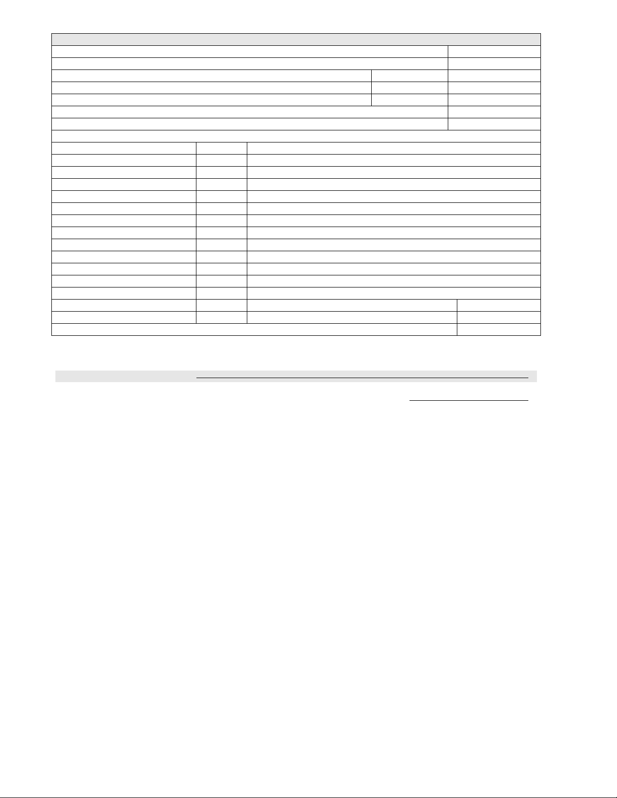
Zone Number ( ) Commissioning
VAV damper actuator properly rigged and verified? ( opens and closes with demand )
Proper adjustments of zone side take off balancing damper?
Proper balancing of zone minimum position? CFM =
Proper balancing of zone maximum position? CFM =
Proper balancing of zone MaxHeatflow position? (If reheat is used) CFM =
Verification of Reheat (If reheat is used)
Maximum Delta temperature of Reheat (If duct reheat is used)
Important configuration property set ?
- Zone MAC:
- PAN ID
- Channel
- RTC MAC:
- Lockout:
- RehtConf: If reheat is used
- AO2 OALK: If reheat is used
- BO5 OALK: If reheat is used
- Heat max:
- Cool min:
- Min Pos:
- Max Pos:
- MaxHTPos:
- PIHT Wei:
- PICL Wei:
Communication with RTU is active? ( Status LED & outdoor temperature display )
Bold items are critical for proper system operation
Is this zone a master in heating?
Is this zone a master in heating?
6) Things You Need to Know
6A) Single 24 VAC Zone Transformer vs. Multi 24 VAC Zone Transformers
It is possible to use a single 24 VAC transformer for each zone controller or you may use a single large
central 24 VAC transformer for many zone controllers.
If using a single 24 VAC for each zone controller.
- Use a 20 VA or more Class2 self protected transformer to power all components attached to the
zone controller.
- Be sure to respect the polarity of all components in the circuit: analog VAV actuator, analog reheat,
etc…
- Be sure that if a ground is required, the common side of the circuit is the one connected to earth (0
V ~ Com). Grounding is required only at one location to prevent ground loops.
If using a large central 24 VAC transformer for many zones.
- If using Class1 unprotected transformer to power all components attached to the ZN controller. Be
sure that the installed fuse or circuit protection is sized according to the maximum installed
required current load. This is not necessarily the same as the maximum current available from the
transformer. Ex.: If a 100 VA transformer is installed and the maximum installed load is 45 VA for
all devices attached, then the fused value should be 2 amps maximum at 24 VAC.
- Be sure to respect the polarity of all components in the circuit: All analog VAV actuator(s), all
analog reheat devices, etc…
- Be sure that if grounded is required, the common side of the circuit is the one connected to earth (0
V ~ Com) Grounding is required only at one location to prevent ground loops.
39
Page 40

6B) Critical Point Checks
To insure proper and reliable operation of the system, it is the responsibility of the system designer or
installer to properly verify all important milestones of the project
.
This includes all other contractual aspects for the system performed outside of the control system scope of
work:
- Design phase: load calculations and ductwork layout and sizing, equipment selection, etc…..
- Construction phase: RTU installation, ductwork installation, electrical work required, etc…
- Commissioning and delivery phase: Operational system checklist, balancing, proper RTU
commissioning, etc….
In order to successfully deliver a fully functional system that will keep customer happy, proper initial design
and proper commissioning are mandatory.
6C) Balancing and Capacity
It is not the mandate of a zoning control system to correct for an incorrect mechanical layout or improper
load calculations of the mechanical zoning equipment. The control system will deliver the loads required by
the master demanding zones by appropriately distributing the total available capacity of the installed
equipment to the required demanding zones.
It should also be noted that even when the equipment is undersized, the control system will distribute the
available capacity according to the priorities requested making most of the areas comfortable.
However, proper air balancing of the main trunks and zones must be done for optimal system operation.
This includes the following:
- Min, Max and HeatMaxflow properly adjusted during balancing.
- Adjustments may need to be done to the main trunk side-take-off directional adjustment blade of
the local VAV trunk is equipped with one.
40
 Loading...