

Page 1
VTR8300 User Interface Guide
VT8300 Room Controller Series
Commercial and Hotel/Lodging HVAC Fan Coil Applications
CONTENTS
Home Screen Display 2
How to Enter Setup Screen 3
Setup Screen Display 3
Network Settings 4
ZigBee® Network Settings 4
BACnet® Network Settings 7
BACnet® Instance Number 8
Configuration Parameters 9
Setpoints Settings 21
Display Settings 23
User HMI - Hospitality 23
User HMI - Commercial 23
Other Functions 24
Customizable Color Options 25
Setpoint Adjustment 26
Service Views 29
Test Outputs Screen 31
Language Selection 32
Page 2
2
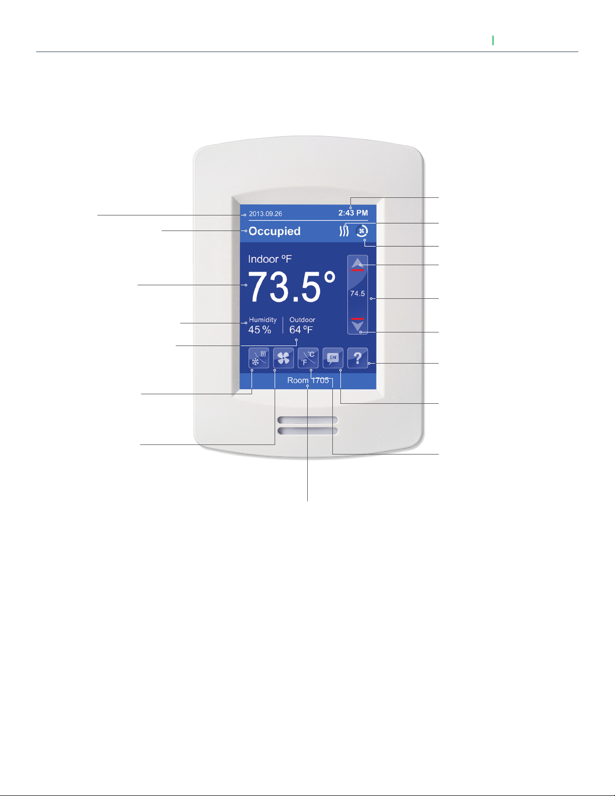
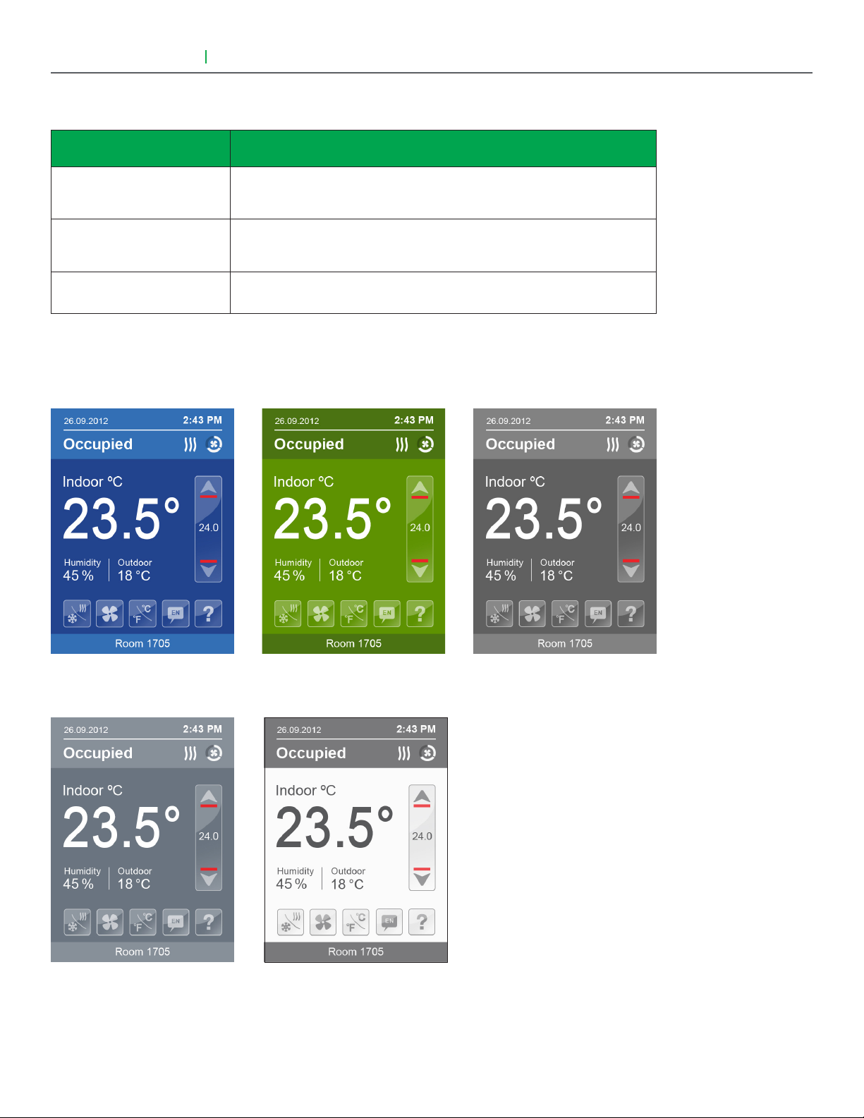
HOME SCREEN DISPLAY
Date
Occupancy Status
Room Indoor
Temperature
Room Indoor Humidity
Outdoor Temperature
User Interface Guide
Hospitality user interface shown
VTR8300 Series
Time
System Status
Fan Status
Up Arrow
Raise Temperature Setpoint
Actual Setpoint
Down Arrow
Lower Temperature Setpoint
Help
Enter help screen
System Mode
Select system mode
Fan Mode
Select fan mode
Language
Select preferred language
Temperature Units
Select Celsius or Fahrenheit units
Short Network Message
Note: User HMI's are configurable, as such the following display functions can be enabled or disabled by setting
various parameters: Date, time, humidity, outdoor temperature, setpoint, buttons, etc.
Viconics Technologies Inc. I Sma ll Building S ystems I 9245 Langelier Blvd. Saint- Leonard, Quebec, Canada, H1P 3K9 I +1 514 321 5660 I ww w.viconics.com
028-6045 -01 April 2014
© 2014 Viconics Technologies. All rights reserved.
Page 3
User Interface Guide
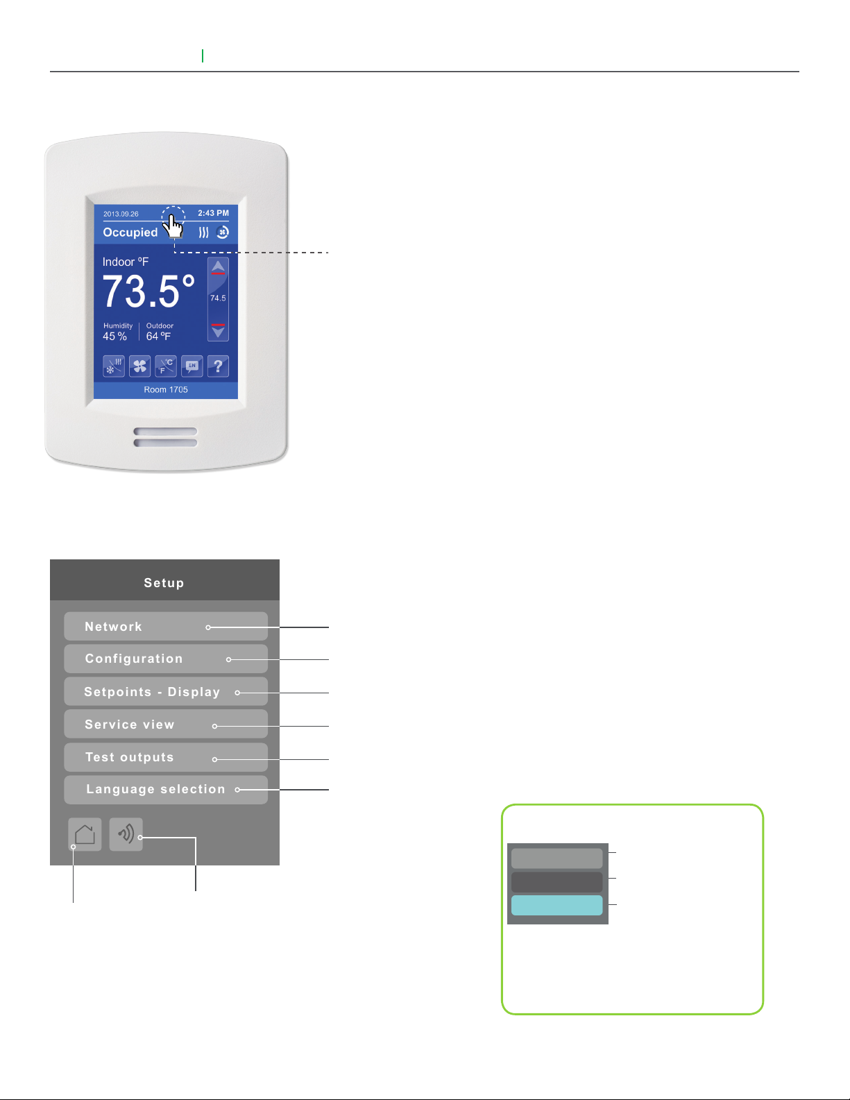
Setup
Network
Configuration
Setpoints - Display
Service view
Test outputs
Language selection
VTR8300 Series
HOW TO ENTER SETUP SCREEN
3
Touch and hold this point
for 3 seconds to enter setup mode
Note: If a configuration / installer
password is activated to prevent
unauthorised access to the
configuration menu parameters, a
password entry prompt will appear
to prevent access to the device
configuration components.
SETUP SCREEN DISPLAY
Return to
home screen
Discover Mode The Controller will
become discoverable on the wireless
ZigBee® network for 1 minute (this
button is hidden if ZigBee® settings are
not configured)
Note: The "Network" button will not be displayed if
no BACnet® or ZigBee® card is installed.
Enter BACnet® & ZigBee® network settings
Enter parameter configuration menu
Enter setpoint & display settings
Enter status and service view
Enter output testing mode
Enable selected language(s)*
General Note:
Adjustable parameter
Nonadjustable parameter
Indicates invisible conditional
field. Appears based only
on model or presence of a
ZigBee® card
*only available in recent versions of firmware
Viconics Technologies Inc. I Sma ll Building S ystems I 9245 Langelier Blvd. Saint- Leonard, Quebec, Canada, H1P 3K9 I +1 514 321 5660 I ww w.viconics.com
028-6045 -01 April 2014
© 2014 Viconics Technologies. All rights reserved.
Page 4
4
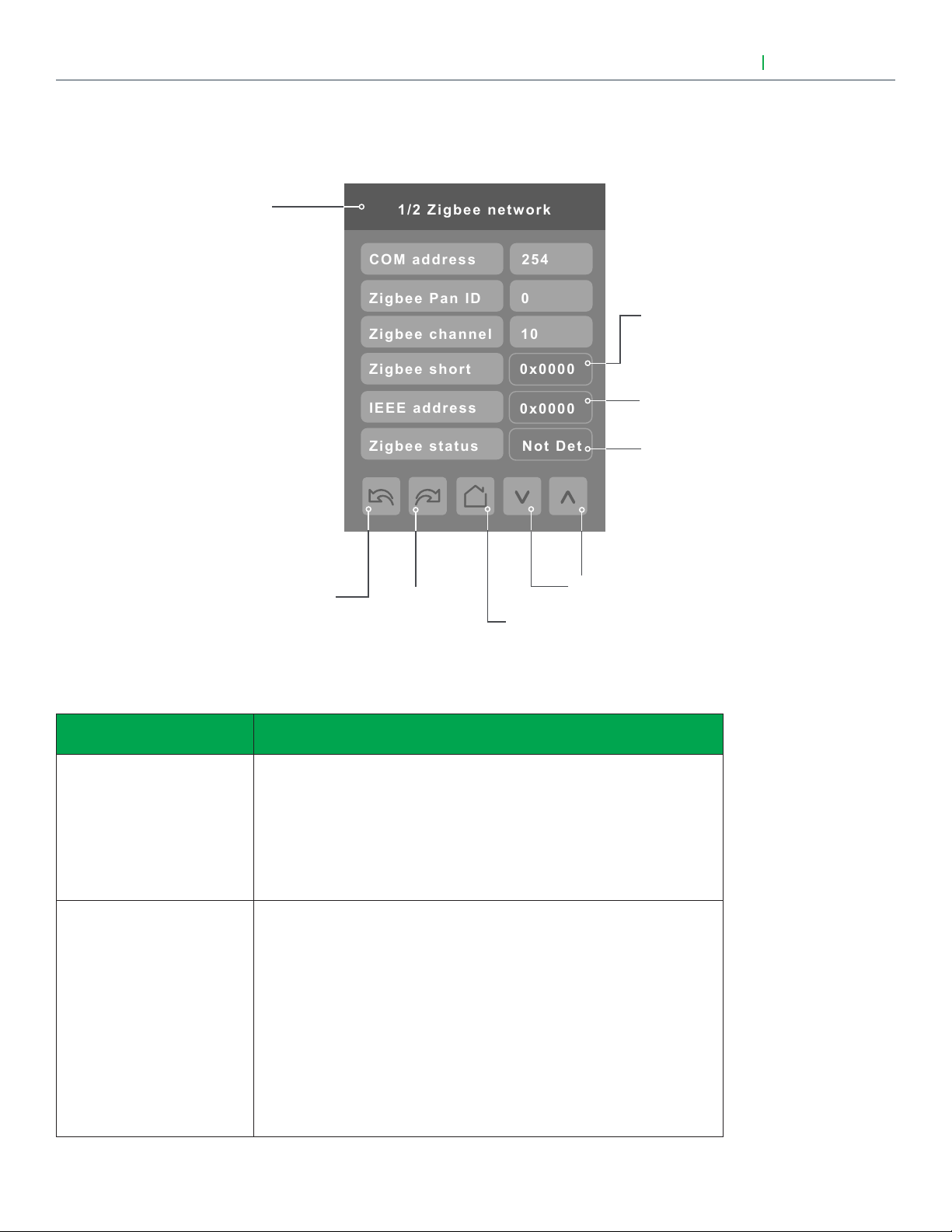
1/2 Zigbee network
Zigbee channel
Zigbee Pan ID
COM address
10
0
254
Zigbee short
0x0000
IEEE address
0x0000
Zigbee status
Not Det
NETWORK SETTINGS
ZIGBEE NETWORK SETTINGS (IF ZIGBEE NETWORK CARD IS INSTALLED)
Page 1 of 2
Note: To change the value of
a parameter, simply press on
the parameter name or value
and then use the arrow keys
to change the value.
User Interface Guide
ZigBee® Pro short address.
The address is generated
once the device joins a
ZigBee® network.
Only the last 4 digits in HEX
are showed
Status of controller
detecting a ZigBee®
network. Will display
Online when connected
successfully to network.
VTR8300 Series
PARAMETER DETAILS
Configuration parameters
default value
COM address
Terminal Equipment
Controller networking address
Default value = 254
Range is: 0 to 254
ZigBee® Pan ID
Personal Area Network
Identification
Default value = 0
Range is: 0 to 1000
Previous
Page
Significance and adjustments
For wireless models, the use of the COM address is not mandatory. The
extended IEEE ZigBee® node address is used to identify the device on the
network.
The COM address is an optional useful way to identify a device on the
network.
This parameter (PAN ID) is used to link specific Terminal Equipment
Controllers to specific ZigBee® coordinators. For every Terminal Equipment
Controller reporting to a coordinator, be sure you set the SAME channel
value both on the coordinator and the Terminal Equipment Controller(s).
The default value of 0 is NOT a valid PAN ID.
The valid range of available PAN ID is from 1 to 1000.
Next
Page
Back to
Setup Page
Change Value
( see note )
Viconics Technologies Inc. I Sma ll Building S ystems I 9245 Langelier Blvd. Saint- Leonard, Quebec, Canada, H1P 3K9 I +1 514 321 5660 I ww w.viconics.com
028-6045 -01 April 2014
Range 1 to 500 for centralized networked applications using a ZigBee®
Coordinator.
Range 501 to 1000 is for stand-alone applications where there is no
ZigBee® Coordinator.
© 2014 Viconics Technologies. All rights reserved.
Page 5

User Interface Guide
VTR8300 Series
PARAMETER DETAILS (CONT'D)
5
Configuration parameters
default value
ZigBee® channel
Channel selection
Default value = 10
Range is: 10 to 25
ZigBee® status
( read only )
Significance and adjustments
This parameter (Channel) is used to link specific Terminal Equipment
Controllers to specific ZigBee® coordinators. For every Terminal Equipment
Controller reporting to a coordinator, be sure you set the SAME channel
value both on the coordinator and the Terminal Equipment Controller(s).
Using channels 15 and 25 is recommended.
The default value of 10 is NOT a valid channel. The valid range of available
channel is from 11 to 25.
( Not Det ): ZigBee® module not detected
( Pwr On ): ZigBee® module detected but not configured
( No NWK ): ZigBee® configured but no network joined
( Joined ): ZigBee® network joined
( Online ): Communicating
Viconics Technologies Inc. I Sma ll Building S ystems I 9245 Langelier Blvd. Saint- Leonard, Quebec, Canada, H1P 3K9 I +1 514 321 5660 I ww w.viconics.com
028-6045 -01 April 2014
© 2014 Viconics Technologies. All rights reserved.
Page 6
6
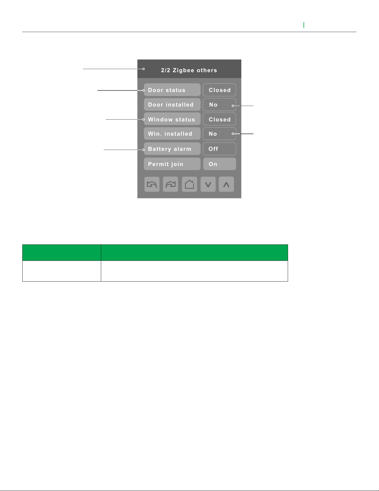
2/2 Zigbee others
Door status
Closed
Door installed
No
Window status
Closed
Win. installed
No
Permit join
On
Battery alarm
Off
ZIGBEE NETWORK SETTINGS (CONT'D)
Page 2 of 2
Status of the door
contact (if installed)
Status of the window
contact (if installed)
Battery alarm of the
wireless switch
User Interface Guide
Indicates if the door
contact is installed
Indicates if the window
contact is installed
VTR8300 Series
Note: The display will return to the home screen when no activity is detected for 1 minute.
PARAMETER DETAILS (CONT'D)
Configuration parameters
default value
Permit join
Default value = On
Significance and adjustments
Changing this value to "Off" will lockout any new ZigBee® devices from
joining the network through this controller.
Viconics Technologies Inc. I Sma ll Building S ystems I 9245 Langelier Blvd. Saint- Leonard, Quebec, Canada, H1P 3K9 I +1 514 321 5660 I ww w.viconics.com
028-6045 -01 April 2014
© 2014 Viconics Technologies. All rights reserved.
Page 7
User Interface Guide
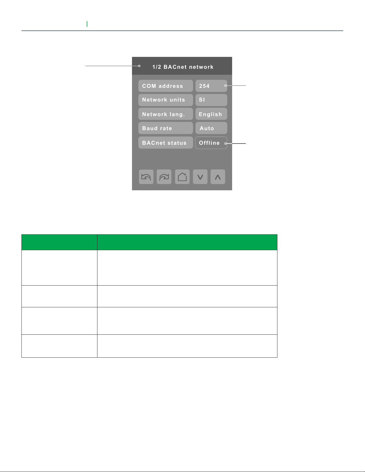
1/2 BACnet network
Baud rate
Auto
Network units
SI
Network lang.
English
BACnet status
Offline
COM address
254
BACNET NETWORK SETTINGS
Page 1 of 2
VTR8300 Series
7
"254" value will set BACnet®
network "Offline". To activate
"Online", choose a different
value
Indicates the controller
status on the network
PARAMETER DETAILS
Configuration parameters
default value
COM address
Terminal Equipment Controller
networking address
Default value = 254
Range is: 0 to 254
Network units
Default value = Imperial
Network lang.
Default value = English
Baud rate
Default value = Auto
Significance and adjustments
For BACnet® MS-TP models, the valid range is from 1 to 127.
Default value of 254 disables BACnet® communication for the Terminal
Equipment Controller.
(Imperial): Network units shown as “imperial” units.
(Si): Network units shown as “international metric” units.
Choice of network language / object names that will be transmitted over
the network.
Other choices: (French) (Spanish).
(Auto): Will automatically detect the BACnet® MS/TP baud rate.
Other choices: (115200) (76800) (57600) (38400) (19200) (9600).
Viconics Technologies Inc. I Sma ll Building S ystems I 9245 Langelier Blvd. Saint- Leonard, Quebec, Canada, H1P 3K9 I +1 514 321 5660 I ww w.viconics.com
028-6045 -01 April 2014
© 2014 Viconics Technologies. All rights reserved.
Page 8
8
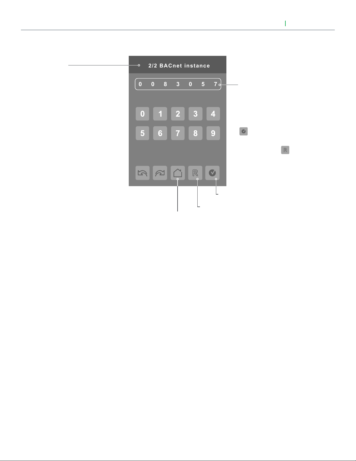
0830057
2/2 BACnet instance
BACNET INSTANCE NUMBER
Page 1 of 2
Note: The default BACnet® instance
number is generated by the model
number and COM address of the
controller.
Example: The instance number of a
VTR8300A500B with a COM address
of 57 will be generated as "83057".
User Interface Guide
Instance number
of the controller.
The default instance number
will appear first. To change
the instance number, use the
number pad and then press
to save changes made.
To reset to automatic instance
addressing, press
VTR8300 Series
Back to
Setup Page
Accept. and save
Reset to automatic
instance addressing
Viconics Technologies Inc. I Sma ll Building S ystems I 9245 Langelier Blvd. Saint- Leonard, Quebec, Canada, H1P 3K9 I +1 514 321 5660 I ww w.viconics.com
028-6045 -01 April 2014
© 2014 Viconics Technologies. All rights reserved.
Page 9
User Interface Guide
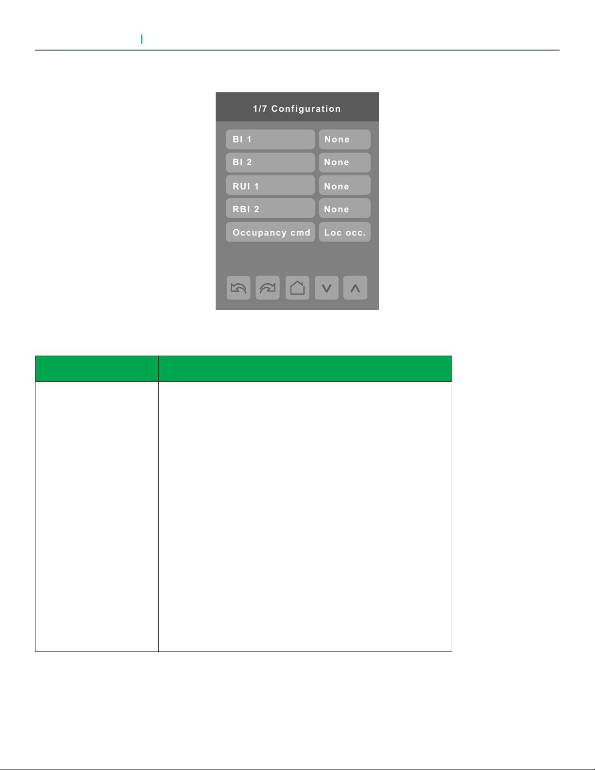
1/7 Configuration
RBI 2
RUI 1
BI 2
BI 1
None
None
None
None
Occupancy cmd
Loc occ.
VTR8300 Series
CONFIGURATION PARAMETERS
9
PARAMETER DETAILS
Configuration parameters
default value
BI 1
Binary input no.1 configuration
Default value = None
Significance and adjustments
(None): No function will be associated with the input. Input can be used for
remote network monitoring.
(Rem NSB): Remote NSB timer clock input. The scheduling will now be
set as per the binary input. It provides low cost setback operation via a dry
contact.
Contact opened = Occupied
Contact closed = Unoccupied
(Motion NO) or (Motion NC): Advanced PIR occupancy functions using a
Normally Open (NO) or Normally Closed (NC) remote PIR motion sensor.
Occupancy mode is now set as per applied PIR function and configuration.
Application information and examples are available on document: APPPIR-Guide-Exx. This document will provide the installers and system
designers with detailed examples on applications, parameter configuration
information, sequence of operation, troubleshooting and diagnostic help
required for the proper usage of the PIR accessory covers.
(Window) EMS: Forces the system to disable any current heating or
cooling action by the Terminal Equipment Controller. The mode stays the
same and the current setpoints are the same Occupied setpoints. Only
the outputs are disabled. There is a Door/Window alarm displayed on the
Terminal Equipment Controller to indicate to the local tenant that the door/
window needs to be closed for cooling or heating to resume.
Viconics Technologies Inc. I Sma ll Building S ystems I 9245 Langelier Blvd. Saint- Leonard, Quebec, Canada, H1P 3K9 I +1 514 321 5660 I ww w.viconics.com
028-6045 -01 April 2014
© 2014 Viconics Technologies. All rights reserved.
Page 10

10
PARAMETER DETAILS (CONT'D)
User Interface Guide
VTR8300 Series
Configuration parameters
default value
BI 2
Binary input no.2 configuration
Default value = None
RUI 1
Remote Universal input
no.1 configuration
Default value = None
Significance and adjustments
(None): No function will be associated with the input. Input can be used for
remote network monitoring.
(Door Dry): Door contact & Motion detector: This configuration is only
functional if binary input #1 is set to Motion NO or Motion NC or a PIR
accessory cover is used.
With this sequence enabled, the occupancy is now dictated through those
2 inputs. Any motion detected will set the zone to occupied status. The
zone will remain permanently in occupied mode until the door contact
switch opens momentarily. The Terminal Equipment Controller will then
go in stand-by mode. If more movements are detected, the occupied
mode will resume. While the door is opened, any movements detected by
the remote PIR sensor or the PIR accessory cover will be ignored. Use a
Normally Closed contact switching device.
• Contact opened = Door opened
• Contact closed = Door closed
(Override): A temporary close contact on input BI 2 will override temporally
to occupied mode.
(None): No function will be associated with the input. Input can be used for
remote network monitoring.
(Filter): "Filter alarm" will be displayed on the Terminal Equipment Controller
LCD screen when the input is energized. It can be tied to a differential
pressure switch that monitor filters.
Contact opened = No alarm
Contact closed = Alarm displayed
(Service): "Service alarm" will be displayed on the Terminal Equipment
Controller LCD screen when the input is energized. It can be tied in to the
AC unit control card, which provides an alarm in case of malfunction.
Contact opened = No alarm
Contact closed = Alarm displayed
(COC/NH) Change over dry contact. Normally Heat: Used for hot / cold
water or air change over switching in 2 pipe systems.
Contact closed = Cold water or air present
Contact opened = Hot water or air present
Only used and valid if system is setup as 2 pipes. Parameter ( Pipe No )
set as 2 pipes.
(COC/NC) Change over dry contact. Normally Cool: Used for hot / cold
water or air change over switching in 2 pipe systems.
Contact closed = Hot water present
Contact opened = Cold water present
Only used and valid if system is setup as 2 pipes. Parameter (Pipe No )
set as 2 pipes.
(COS) Change over analog sensor: Used for hot / cold water or air change
over switching in 2 pipe systems.
Only used and valid if system is setup as 2 pipes. Parameter (Pipe No )
set as 2 pipes.
If water temperature is > 26 °C ( 78 °F )= Hot water present
If water temperature is < 24 °C ( 75 °F )= Cold water present
Viconics Technologies Inc. I Sma ll Building S ystems I 9245 Langelier Blvd. Saint- Leonard, Quebec, Canada, H1P 3K9 I +1 514 321 5660 I ww w.viconics.com
028-6045 -01 April 2014
© 2014 Viconics Technologies. All rights reserved.
Page 11

User Interface Guide
VTR8300 Series
PARAMETER DETAILS (CONT'D)
11
Configuration parameters
default value
RBI 2
Remote Binary input
no.2 configuration
Default value = None
Occupancy cmd
Significance and adjustments
(None): No function will be associated with the input. Input can be used for
remote network monitoring.
(Filter): "Filter alarm" will be displayed on the Terminal Equipment Controller
LCD screen when the input is energized. It can be tied to a differential
pressure switch that monitor filters.
Contact opened = No alarm
Contact closed = Alarm displayed
(Service): "Service alarm" will be displayed on the Terminal Equipment
Controller LCD screen when the input is energized. It can be tied in to the
AC unit control card, which provides an alarm in case of malfunction.
Contact opened = No alarm
Contact closed = Alarm displayed
(Loc Occ): Occupancy is determined by local sequences
(Occupied): Force occupied mode
(Unoccup): Force unoccupied mode
Viconics Technologies Inc. I Sma ll Building S ystems I 9245 Langelier Blvd. Saint- Leonard, Quebec, Canada, H1P 3K9 I +1 514 321 5660 I ww w.viconics.com
028-6045 -01 April 2014
© 2014 Viconics Technologies. All rights reserved.
Page 12

12
Auto mode
Enabled
2/7 Configuration
Fan menu
On-Auto
Auto fan func.
AS
Fan cont. heat
On
Standby diff.
2.0 °C
Standby mode
Abs
CONFIGURATION PARAMETERS (CONT'D)
User Interface Guide
VTR8300 Series
PARAMETER DETAILS (CONT'D)
Configuration parameters
default value
Auto mode
Enables Auto menu
for Mode button
Default value = On
Fan menu
Mode button menu
configuration
Default is: On-Auto
Significance and adjustments
Enables Auto function for the mode button
For sequences 2, 4 & 5 only
On = Auto active (Off-Cool-Heat-Auto)
Off = auto not active (Off-Cool-Heat)
Menu presented are dependent on model used and sequence of operation
selected.
(L-M-H): 3 Speed configuration using 3 fan relays.
(L-H): 2 Speed configuration using 2 fan relays.
(L-M-H-A): 3 Speed configuration with Auto fan speed mode using 3 fan
relays.
(Auto Mode operation is dependent on Auto Fan parameter).
(L-H-A): 2 Speed configuration with Auto fan speed mode using 2 fan
relays.
(Auto Mode operation is dependent on Auto Fan parameter).
(On-Auto): Single Speed configuration. Auto is for Fan on demand / On is
On all the time.
Auto fan func.
Auto Fan Function
Default value: AS
Viconics Technologies Inc. I Sma ll Building S ystems I 9245 Langelier Blvd. Saint- Leonard, Quebec, Canada, H1P 3K9 I +1 514 321 5660 I ww w.viconics.com
028-6045 -01 April 2014
Auto Speed Fan Mode operation for Fan Menu (L-M-H-A) or (L-H-A).
(AS): Auto Speed during occupied periods. Fan is always on during
occupied periods.
(AS AD): Auto Speed / Auto Demand during occupied periods.
© 2014 Viconics Technologies. All rights reserved.
Page 13

User Interface Guide
VTR8300 Series
PARAMETER DETAILS (CONT'D)
13
Configuration parameters
default value
Fan cont. heat
Default is: On
Standby mode
Default value: Abs
Standby diff.
Default value: 2 °C ( 3 °F )
Significance and adjustments
Fan control in heating mode.
(On): the controller in all cases will always control the fan (terminals LowMed—Hi Fan Speed). Valid in any fan sequences and all the available fan
modes.
(Off Auto): the controller in all cases will disable the fan (any terminals LowMed—Hi Fan Speed). ONLY when the local fan mode is set to Auto. Valid
in all fan sequences with auto mode.
(Off All): the controller in all cases will disable the fan (any terminals LowMed—Hi Fan Speed). When the local fan mode is set to ANY mode. Valid
in all fan sequences and all local fan modes.
Choose which standby setpoints are used for control.
(Abs): “Absolute” Standby entered values are used for standby mode.
(Offset): “Offset” Occupied setpoints +/- “Standby diff.” is used for standby
mode.
When “Standby mode” is “Relative”, standby setpoints are calculated as:
“Standby cool” = “Cool setpoint” + “Standby diff.”
“Standby heat” = “Heat setpoint” - “Standby diff.”
Adjustable from 0.5 a 2.5 °C ( 1 to 5 °F )
Viconics Technologies Inc. I Sma ll Building S ystems I 9245 Langelier Blvd. Saint- Leonard, Quebec, Canada, H1P 3K9 I +1 514 321 5660 I ww w.viconics.com
028-6045 -01 April 2014
© 2014 Viconics Technologies. All rights reserved.
Page 14

14
3/7 Configuration
Temp. occ. time
Unocc. time
Standby time
2.0 hrs
0.0 hrs
0.5 hrs
Deh hysteresis
5.0% RH
Deh. max cool
100%
Deh. lockout
Enabled
CONFIGURATION PARAMETERS (CONT'D)
These parameters are model
dependent and may not appear
on certain models.
User Interface Guide
VTR8300 Series
PARAMETER DETAILS
Configuration parameters
default value
Standby time
Default 0.5 hours
Unocc. time
Default 0.0 hours
Temp. occ. time
Default value = 2 hours
Deh. hysteresis
Default value = 5 % RH
Significance and adjustments
Time delay between the moment where the PIR cover detected the
last movement in the area and the time which the Terminal Equipment
Controller stand-by setpoints become active.
Range is: 0.5 to 24.0 hours in 0.5 hours increments.
Time delay between the moment where the Terminal Equipment Controller
toggles to stand-by mode and the time which the Terminal Equipment
Controller unoccupied mode and setpoints become active.
The factory value or 0.0 hours: Setting this parameter to its default value
of 0.0 hours disables the unoccupied timer. This prevents the Terminal
Equipment Controller to drift from stand-by mode to unoccupied mode
when PIR functions are used.
Range is: 0.0 to 24.0 hours in 0.5 hours increments.
Temporary occupancy time with occupied mode setpoints when override
function is enabled.
When the Terminal Equipment Controller is in unoccupied mode, function
is enabled with either the menu or UI2 configured as remote override input.
Range is: 0 to 24 hours in 1 hour increments.
Humidity control hysteresis. Used only if dehumidification sequence is
enabled:
Viconics Technologies Inc. I Sma ll Building S ystems I 9245 Langelier Blvd. Saint- Leonard, Quebec, Canada, H1P 3K9 I +1 514 321 5660 I ww w.viconics.com
028-6045 -01 April 2014
Range is: 2 to 20% RH.
(Models with humidity sensor only).
© 2014 Viconics Technologies. All rights reserved.
Page 15

User Interface Guide
VTR8300 Series
PARAMETER DETAILS (CONT'D)
15
Configuration parameters
default value
Deh. max. cool.
Default value = 100 %
Deh. lockout
Default value: Enabled
Significance and adjustments
Maximum cooling valve position when dehumidification is enabled. This
can be used to balance smaller reheat loads installed in regards to the
capacity of the cooling coil.
Range is: 20 to 100 %.
(Models with humidity sensor only).
Dehumidification lockout, typically toggled through the network.
This variable enables or disables dehumidification based on central
network requirements from the BAS front end.
Enabled = Dehumidification Authorized
Disabled = Dehumidification Not Authorized
(Models with humidity sensor only).
Viconics Technologies Inc. I Sma ll Building S ystems I 9245 Langelier Blvd. Saint- Leonard, Quebec, Canada, H1P 3K9 I +1 514 321 5660 I ww w.viconics.com
028-6045 -01 April 2014
© 2014 Viconics Technologies. All rights reserved.
Page 16
16
Heating valve
Cooling valve
Heat CPH
Cool CPH
NC
NC
4
4
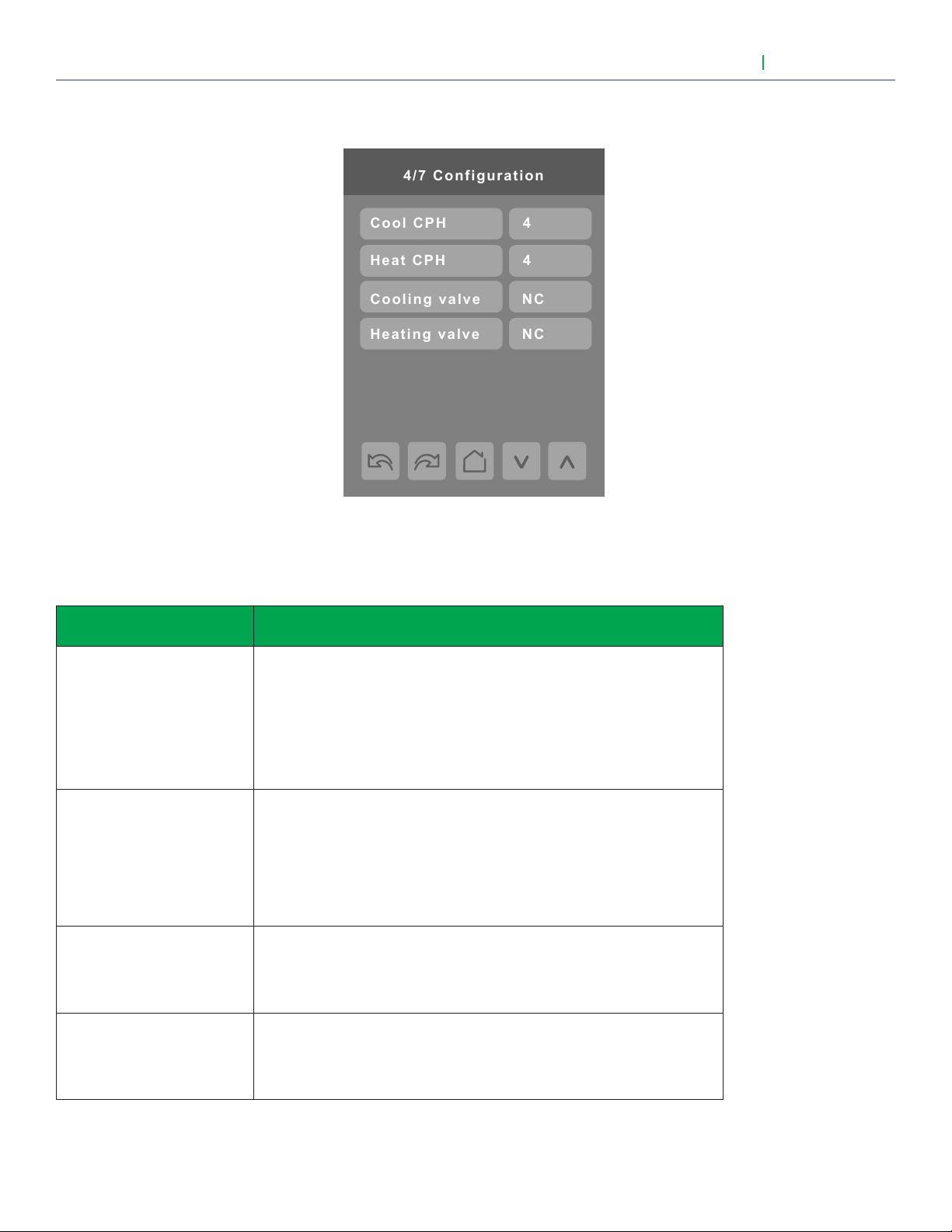
4/7 Configuration
CONFIGURATION PARAMETERS (CONT'D)
User Interface Guide
VTR8300 Series
PARAMETER DETAILS
Configuration parameters
default value
Cool CPH
Default value = 4 C.P.H.
Heat CPH
Default value = 4 C.P.H.
Cooling valve
Default value = NC
Heating valve
Default value = NC
Significance and adjustments
Cooling output cycles per hour. Will set the maximum number cycles per
hour under normal control operation. It represents the maximum number
of cycles that the equipment will turn ON and OFF in one hour.
Note that a higher C.P.H will represent a higher accuracy of control at the
expense of wearing mechanical components faster.
Range is: 3, 4, 5, 6,7 & 8 C.P.H.
Heating output cycles per hour. Will set the maximum number cycles per
hour under normal control operation. It represents the maximum number
of cycles that the equipment will turn ON and OFF in one hour.
Note that a higher C.P.H will represent a higher accuracy of control at the
expense of wearing mechanical components faster.
Range is: 3, 4, 5, 6,7 & 8 C.P.H.
Set’s the type of valve used for cooling
NC = Valve is normally closed when no power is present.
NO = Valve is normally opened when no power is present.
Set’s the type of valve used for heating.
NC = Valve is normally closed when no power is present.
Viconics Technologies Inc. I Sma ll Building S ystems I 9245 Langelier Blvd. Saint- Leonard, Quebec, Canada, H1P 3K9 I +1 514 321 5660 I ww w.viconics.com
028-6045 -01 April 2014
NO = Valve is normally opened when no power is present.
© 2014 Viconics Technologies. All rights reserved.
Page 17
User Interface Guide
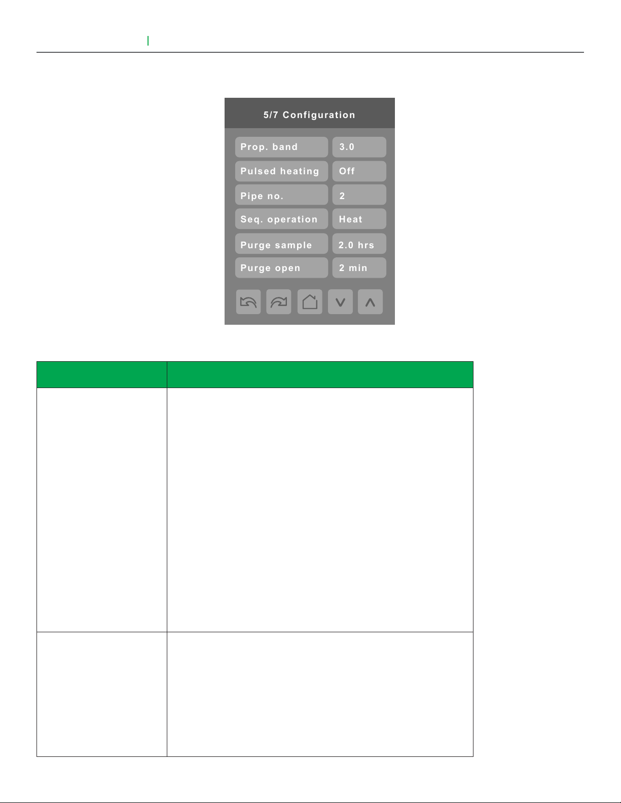
5/7 Configuration
Seq. operation
Pipe no.
Pulsed heating
Heat
2
Off
Prop. band
3.0
Purge sample
2.0 hrs
Purge open
2 min
VTR8300 Series
CONFIGURATION PARAMETERS (CONT'D)
17
PARAMETER DETAILS
Configuration parameters
default value
Prop. band
Default is : 3
Significance and adjustments
Proportional band setting. Adjusts the proportional band used by the
Terminal Equipment Controller PI control loop.
Warning: Note that the default value of 3.0 gives satisfactory operation
in most normal installation cases. The use of a superior proportional band
different than the factory one is normally warranted in applications where
the Terminal Equipment Controller location is problematic and leads to
unwanted cycling of the unit. A typical example is a wall mounted unit
where the Terminal Equipment Controller is installed between the return
and supply air feeds and is directly influenced by the supply air stream of
the unit.
Effective
Proportional band
Value °F °C
3 3 1.2
4 4 1.7
5 5 2.2
6 6 2.8
7 7 3.3
8 8 3.9
9 9 5.0
10 10 5.6
Pulsed heating
Default Value = Off
VDC output configuration. VC3000 series model dependent.
Off = Regular On-Off control for VC350xE models only.
Can be used with 2 & 4 pipes applications.
On = VDC SSR electric heat 10 second pulsed time base modulation for
SC340xE models only.
Can only be used with 2 pipes system only.
Occ Out = VDC Occupancy output follows local device occupancy for
SC3514E model only.
Occupied & Temporary Occupied = Contact closed
Stand-By & Unoccupied = Contact opened
Viconics Technologies Inc. I Sma ll Building S ystems I 9245 Langelier Blvd. Saint- Leonard, Quebec, Canada, H1P 3K9 I +1 514 321 5660 I ww w.viconics.com
028-6045 -01 April 2014
© 2014 Viconics Technologies. All rights reserved.
Page 18
18
PARAMETER DETAILS (CONT'D)
User Interface Guide
VTR8300 Series
Configuration parameters
default value
Pipe no.
Default is: 2.0 Pipes
Seq. operation
Default is: Heat
Cool
Heat
Ht-Cl
Ht-Rht
Reheat
Purge sample
Default is: 2 hrs
Significance and adjustments
System type installation: Number of pipes. Defines the type of system
installed.
Selects the initial sequence of operation required by the installation type
and the application.
2 Pipes 4 Pipes
Cooling only Cooling only
Heating only Heating only
Cooling with electric reheat Heating / Cooling
Heating with electric reheat ---
Electric reheat only ---
For 2 Pipe output applications, the system access is limited if RUI 1 is
configured for local changeover COS, COC/NC or COC/NC. The current
water temperature detected by the RUI 1 then limits the system mode
available for the local configuration or network write.
For sequence “electric reheat”, set PulsedHt to "On" to enable pulsed
electric reheat applications with SC3400E & SC3404E.
Time interval between valve samples. Will open valve for a short period
(adjusted by “Purge open” parameter to sample pipe temperature (to
decide between heating or cooling mode).
Purge open
Default is: 2 min
Adjustable for 0 to 4 hrs.
(0 = disable this function).
Time the valve will open to sample pipe temperature (to decide between
heating or cooling mode).
Adjustable for 1 to 3 min.
Viconics Technologies Inc. I Sma ll Building S ystems I 9245 Langelier Blvd. Saint- Leonard, Quebec, Canada, H1P 3K9 I +1 514 321 5660 I ww w.viconics.com
028-6045 -01 April 2014
© 2014 Viconics Technologies. All rights reserved.
Page 19

User Interface Guide
6/7 Configuration
Calib. temp.
User password
Main password
0.0 C
0
0
Calib. humid.
0% RH
VTR8300 Series
CONFIGURATION PARAMETERS (CONT'D)
Parameter only displayed on
models with built in humidity
sensor.
19
PARAMETER DETAILS
Configuration parameters
default value
Main password
Default value = 0
User password
Default value = 0
Calib. temp.
Default value = 0.0 °C or °F
Calib. humid.
Default value = 0 %RH
Significance and adjustments
Installer’s password. This parameter sets a protective access password
to prevent unauthorized access to the configuration menu parameters. A
default value of “0” will not prompt a password or lock the access to the
configuration menu.
Range is: 0 to 9999.
User’s password. This parameter sets a protective access password to
prevent user unauthorized access to main screen adjustments. A default
value of “0” will not prompt for a password.
Range is: 0 to 9999.
Room temperature sensor calibration. Offset that can be added/
subtracted to actual displayed room temperature.
Range is: ± 2.5 °C, 0.1 °C increments ( ± 5.0 °F, 0.1 °F increments ).
Humidity sensor calibration. Offset that can be added/subtracted to actual
displayed humidity.
Range is : ± 15.0 %RH.
(Models with humidity sensor only).
Viconics Technologies Inc. I Sma ll Building S ystems I 9245 Langelier Blvd. Saint- Leonard, Quebec, Canada, H1P 3K9 I +1 514 321 5660 I ww w.viconics.com
028-6045 -01 April 2014
© 2014 Viconics Technologies. All rights reserved.
Page 20

20
Erase all ?
no
Are you sure ?
no
Push to accept
7/7 Reinitialization
CONFIGURATION PARAMETERS (CONT'D)
User Interface Guide
Accept changes
VTR8300 Series
PARAMETER DETAILS
Configuration parameters
default value
Erase all ?
Are you sure ?
Default values = No
Significance and adjustments
Answering “Yes” to these two questions and pressing the “Accept” button,
will erase all values to factory’s default values except networked related
values:
COM address, ZigBee® Pan ID, ZigBee® channel, Network units, Network
lang., Baud rate, BACnet® instance, Device name.
Viconics Technologies Inc. I Sma ll Building S ystems I 9245 Langelier Blvd. Saint- Leonard, Quebec, Canada, H1P 3K9 I +1 514 321 5660 I ww w.viconics.com
028-6045 -01 April 2014
© 2014 Viconics Technologies. All rights reserved.
Page 21

User Interface Guide
1/2 Setpoints
Occ. cool.
Standby cool.
Unocc. cool.
25.5 °C
24.0 °C
22.0 °C
20.5 °C
16.5 °C
26.5 °C
Occ. heat.
Standby heat.
Unocc. heat.
SETPOINT SETTINGS
VTR8300 Series
21
PARAMETER DETAILS
Configuration parameters
default value
Unocc. cool.
Default value = 26.5 °C
( 80 °F )
Standby cool.
Default value = 25.5 °C
(78 °F )
Occ. cool.
Default value = 24.0 °C
( 74 °F )
Occ. heat.
Default value = 22.0 °C
( 72 °F )
Standby heat.
Default value = 20.5 °C
( 69 °F )
Significance and adjustments
Unoccupied cooling setpoint range is:
12.0 to 37.5 °C ( 54 to 100 °F )
Standby cooling setpoint. The value of this parameter should be set
between the occupied and unoccupied cooling setpoints. Make sure that
the difference between the stand-by and occupied value can be recovered
in a timely fashion when movement is detected in the zone.
Stand-by cooling setpoint range is: 12.0 to 37.5 °C ( 54 to 100 °F ).
Cooling setpoint range is:
12.0 to 37.5 °C ( 54 to 100 °F ).
Heatling setpoint range is:
12.0 to 37.5 °C ( 54 to 100 °F ).
Stand-by heating setpoint. The value of this parameter should be set
between the occupied and unoccupied heating setpoints. Make sure that
the difference between the stand-by and occupied value can be recovered
in a timely fashion when movement is detected in the zone.
Unocc. heat.
Default value = 16.5 °C
( 62 °F )
Viconics Technologies Inc. I Sma ll Building S ystems I 9245 Langelier Blvd. Saint- Leonard, Quebec, Canada, H1P 3K9 I +1 514 321 5660 I ww w.viconics.com
028-6045 -01 April 2014
Stand-by heating setpoint range is: 4.5 to 32.0 °C ( 40 to 90 °F ).
Unoccupied heating setpoint range is:
4.5 to 32.0 °C ( 40 to 90 °F ).
© 2014 Viconics Technologies. All rights reserved.
Page 22

22
12.0 C
2/2 Setpoints
Max. heating
Min. deadband
Default heat
26.0 C
Min. cooling
Dehumidify
1.5 C
32.0 C
50% RH
SETPOINT SETTINGS (CONT'D)
Parameter only displayed on
models with built in humidity
sensor.
User Interface Guide
VTR8300 Series
PARAMETER DETAILS
Configuration parameters
default value
Default heat
Default value = 22.0 °C
( 73 °F )
Min. deadband
Default value = 1.5 °C
( 3.0 °F )
Max heating
Default value = 32.0 °C
( 90.0 °F )
Min. cooling
Default value = 12.0 °C
( 54.0 °F )
Significance and adjustments
This function is used for hospitality applications in stand-alone mode only.
When the devices is in deep unoccupied mode, any movement detected
by the PIR will reset the actual occupied set points to the “fresh room”
default setting.
This default setpoint is used to write to the “Heating setpoint” when the
thermostat goes to “Unoccupied” mode. Cooling setpoint will be set
according to the “Min. deadband”. 18.0 to 26.5 °C ( 65 to 80 °F ).
This parameter is only used when “Stand-by mode” = “Rel”.
Minimum deadband value between the heating and cooling setpoints.
It will be applied only when any of the setpoints are modified.
Range is: 1.0 to 2.5 °C, 0.5 °C increments ( 2, 3, 4 or 5 °F,
1.0 °F increments ).
Maximum occupied & unoccupied heating setpoint adjustment.
Range: 4.5 to 32.0 °C ( 40 to 90 °F ).
Minimum occupied & unoccupied cooling setpoint adjustment.
Range: 12.0 to 37.5 °C ( 54 to 100 °F ).
Dehumidify
Default value = 50 % RH
Viconics Technologies Inc. I Sma ll Building S ystems I 9245 Langelier Blvd. Saint- Leonard, Quebec, Canada, H1P 3K9 I +1 514 321 5660 I ww w.viconics.com
028-6045 -01 April 2014
Dehumidification setpoint. Used only if dehumidification sequence is
enabled:
Range is: 30-95% RH.
(Models with humidity sensor only).
© 2014 Viconics Technologies. All rights reserved.
Page 23

User Interface Guide
1/2 Display
Color
White
User HMI
0
Main display
Temp.
Standby screen
No
DISPLAY SETTINGS
VTR8300 Series
23
PARAMETER DETAILS
Configuration parameters
default value
User HMI
Default value = 0
Significance and adjustments
Select user HMI type.
Range: 0 to 11.
User HMI - Hospitality
0 (Hospitality) 1 (Hospitality) 2 (Hospitality) 3 (Hospitality)
These parameters are model dependent and may not appear on certain models.
Viconics Technologies Inc. I Sma ll Building S ystems I 9245 Langelier Blvd. Saint- Leonard, Quebec, Canada, H1P 3K9 I +1 514 321 5660 I ww w.viconics.com
028-6045 -01 April 2014
© 2014 Viconics Technologies. All rights reserved.
Page 24

24
User HMI - Hospitality
4 (Hospitality) 5 (Hospitality) 6 (Hospitality)
User HMI - Commercial
User Interface Guide
VTR8300 Series
7 (Commercial) 8 (Commercial) 9 (Commercial) 10 (Commercial)
11 (Commercial)
Note: The day/nite setback button
appears only in unoccupied mode from
7 to 11 in HMI Commercial. If BI2 input is
configured as "override", then the day nite
setback button won't appear.
These parameters are model dependent and may not appear on certain models.
Viconics Technologies Inc. I Sma ll Building S ystems I 9245 Langelier Blvd. Saint- Leonard, Quebec, Canada, H1P 3K9 I +1 514 321 5660 I ww w.viconics.com
028-6045 -01 April 2014
© 2014 Viconics Technologies. All rights reserved.
Page 25

User Interface Guide
Other functions
VTR8300 Series
RH Display = Configuration + model dependent
Outdoor Temp = When set by network
25
If main display parameter
is set to "setpoint",
the setpoint value will
display as shown:
On/Off will display
when the sequence
of operation is set to
heating or cooling only
Heating only
Time and Date will
display only if it has
been properly set
(from the network)
Viconics Technologies Inc. I Sma ll Building S ystems I 9245 Langelier Blvd. Saint- Leonard, Quebec, Canada, H1P 3K9 I +1 514 321 5660 I ww w.viconics.com
028-6045 -01 April 2014
© 2014 Viconics Technologies. All rights reserved.
Page 26
26
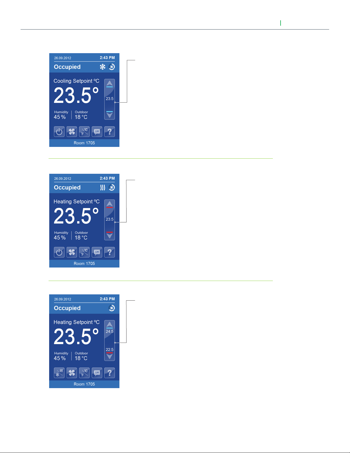
Setpoint Adjustment
User Interface Guide
Cooling mode or cooling only
sequence of operation
In Cooling mode, the setpoint displayed in the bar is the
current occupied cooling setpoint.
During occupied setpoint adjustment, the large digits are
temporarily used to display the occupied cooling setpoint
while it is adjusted.
Normal temperature display resumes after the setpoint
is adjusted and the actual occupied cooling setpoint is
displayed in the setpoint bar.
Heating mode or heating only
sequence of operation
VTR8300 Series
In Heating mode, the setpoint displayed in the bar is the
current occupied heating setpoint.
During occupied setpoint adjustment, the large digits are
temporarily used to display the occupied heating setpoint.
Normal temperature display resumes after the setpoint
is adjusted and the actual occupied heating setpoint is
displayed in the setpoint bar.
Automatic Heating / Cooling mode
In automatic mode, the setpoint displayed at the top
of the set point bar located directly under the blue line
represent the actual occupied cooling setpoint.
During occupied setpoints adjustment, the large digits
are temporarily used to display the occupied “Cooling
Setpoint” or occupied “Heating Setpoint”. The actual
setpoint is dependent on the last effective demand
(heating or cooling).
Normal temperature display resumes after the setpoints
are adjusted and the actual occupied heating and
cooling setpoints are displayed in the setpoint bar.
Viconics Technologies Inc. I Sma ll Building S ystems I 9245 Langelier Blvd. Saint- Leonard, Quebec, Canada, H1P 3K9 I +1 514 321 5660 I ww w.viconics.com
028-6045 -01 April 2014
© 2014 Viconics Technologies. All rights reserved.
Page 27
User Interface Guide
VTR8300 Series
PARAMETER DETAILS (CONT'D)
27
Configuration parameters
default value
Color
Significance and adjustments
Select user HMI color.
Default value = Blue
Other choices: Green, Dark Grey, Grey and White.
Main display
Select default value displayed on main display: Temperature or setpoint.
Default value = Temp.
Choices: Temperature or setpoint.
Disp. cust. img.
Default value = No
Selecting "Yes" will display a custom image after 2 minutes of touch
screen inactivity.
Customisable colour options
Blue Green Dark Grey
Grey White
Viconics Technologies Inc. I Sma ll Building S ystems I 9245 Langelier Blvd. Saint- Leonard, Quebec, Canada, H1P 3K9 I +1 514 321 5660 I ww w.viconics.com
028-6045 -01 April 2014
© 2014 Viconics Technologies. All rights reserved.
Page 28

28
5%
2/2 Display
Low backlight
Units
Language
English
Night backlight
°C
60%
Disabled
RH display
DISPLAY SETTINGS (CONT'D)
Parameter only displayed on
models with built in humidity
sensor.
User Interface Guide
VTR8300 Series
PARAMETER DETAILS
Configuration parameters
default value
Language
Default value = English
°C or °F
Default value = °C
Low backLight
Default value is 60%
Night backLight
Default value = 5%
RH display
Default value = Disabled
Significance and adjustments
Select language for main display.
Choices: English, French, Spanish, Chinese.
This sets the default value when the Terminal Equipment Controller powers
up.
°C for Celsius scale.
°F for Fahrenheit scale.
Set the display’s backlight intensity after 2 minutes of keyboard inactivity.
Adjustable from: 0 to 100%.
Set the display’s backlight intensity after 2 minutes of keyboard inactivity.
Adjustable from: 0 to 100%.
(This parameter is only available for models with motion/light detectors.
The screen backlight will progessively decrease down to this setting when
room is dark).
Enables the display of humidity below the room temperature on the display
(On): Display %RH.
Viconics Technologies Inc. I Sma ll Building S ystems I 9245 Langelier Blvd. Saint- Leonard, Quebec, Canada, H1P 3K9 I +1 514 321 5660 I ww w.viconics.com
028-6045 -01 April 2014
(Off): Do not display %RH.
(Only available on models with humidity sensor).
© 2014 Viconics Technologies. All rights reserved.
Page 29
User Interface Guide
1/6 Service view
Room temp.
xx.x °C
Room humidity
Firmware rev.
1.0
xx.x °C
UI20 RS temp.
xx.x °C
UI19ChgOver
xx.x °C
Outdoor temp.
xx.x %RH
2/5 Service view
PI heat. dem.
0%
0%
PI cool. dem.
Heat dem. limit
0.0%
0.0%
Cool. dem. limit
Effective occ.
Occupied
VTR8300 Series
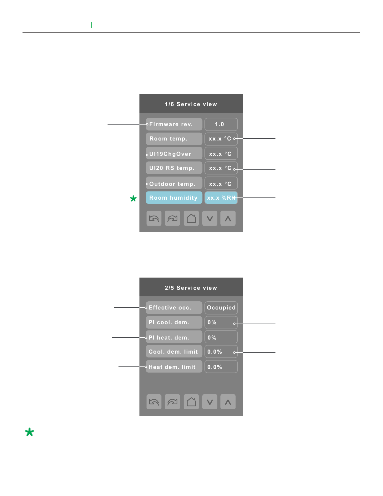
SERVICE VIEWS
The service view screens show the current status of certain points locally at the
controller. These points can also be viewed through the network.
Firmware revision
of the controller
Changeover temperature
Outdoor temperature
29
Room temperature
Supply temperature
Room Humidity
Effective occupancy
PI cooling demand
PI heating demand
Cooling demand limit
Heating demand limit
Parameter only displayed on
models with built in humidity
sensor.
Viconics Technologies Inc. I Sma ll Building S ystems I 9245 Langelier Blvd. Saint- Leonard, Quebec, Canada, H1P 3K9 I +1 514 321 5660 I ww w.viconics.com
028-6045 -01 April 2014
© 2014 Viconics Technologies. All rights reserved.
Page 30
30
3/5 Service view
BI 1
RBI 2
RUI 1
BI 2
Activated
Activated
Not activ
Not activ
Filter alarm
Window alarm
Off
Off
Off
Service alarm
Local motion
On
4/6 Service view
Deh. status
Off
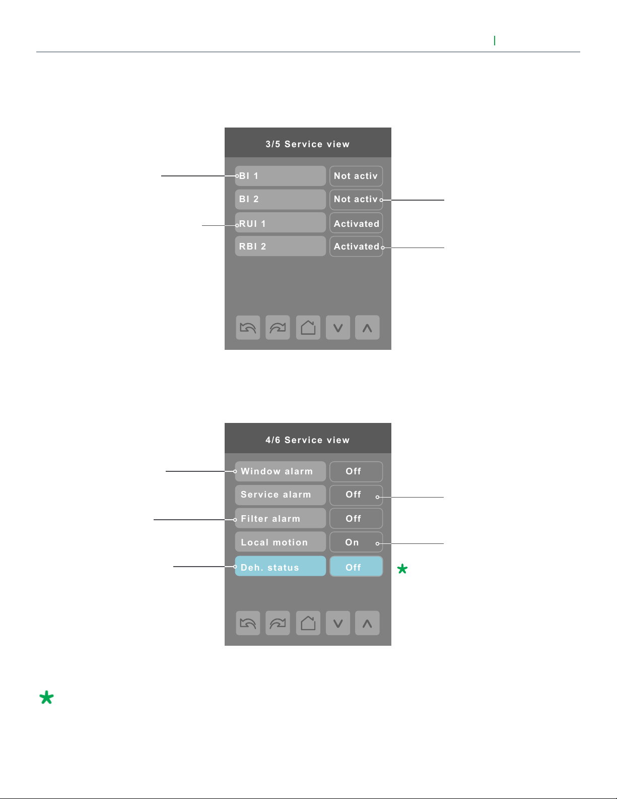
SERVICE VIEWS (CONT'D)
Binary 1 input
Remote universal input 1
User Interface Guide
Binary input 2
Remote universal input 2
VTR8300 Series
Window alarm
Service alarm
Filter alarm
Local motion (on
board detector)
Dehumidification
Parameter only displayed on
models with built in humidity
sensor.
Viconics Technologies Inc. I Sma ll Building S ystems I 9245 Langelier Blvd. Saint- Leonard, Quebec, Canada, H1P 3K9 I +1 514 321 5660 I ww w.viconics.com
028-6045 -01 April 2014
© 2014 Viconics Technologies. All rights reserved.
Page 31
User Interface Guide
5/5 Service view
Device name:
VTR83xxAxxxx
Fan high speed
Heating output
Cooling output
Off
Off
Off
Fan med. speed
Off
Fan low speed
Off
Pulsed HT dem.
0%
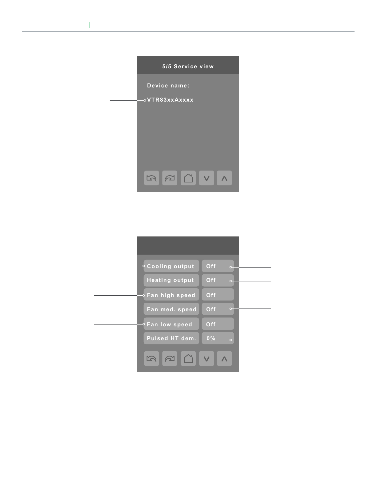
SERVICE VIEWS (CONT'D)
Note: This represents
BACnet® device name
automatically assigned
using the current BACnet®
MAC address.
The network can
update and change the
device BACnet® name.
If changed, the new
updated BACnet® device
name will be shown
VTR8300 Series
31
TEST OUTPUTS SCREEN
1/1 Test outputs
Cooling output
( see note 1 )
High speed
fan output
Low speed
fan output
Note 1: Cooling output can also be used for heating on two pipes systems.
See note 2
Heating output
Medium speed
output
Pulsed heating
demand
Note 2: The test output screen allows manual override of specified outputs. When any BACnet® network
priority array includes a value, the status background is shown in red. After any output state is overridden, the
command is cancelled after 1 min of screen inactivity (auto exit to main screen) or when page is exited. Please
refer to the BACnet® integration guide for more details.
Viconics Technologies Inc. I Sma ll Building S ystems I 9245 Langelier Blvd. Saint- Leonard, Quebec, Canada, H1P 3K9 I +1 514 321 5660 I ww w.viconics.com
028-6045 -01 April 2014
© 2014 Viconics Technologies. All rights reserved.
Page 32
32
Language Selection
Chinese
Spanish
French
Enabled
Enabled
Enabled
Russian
Enabled
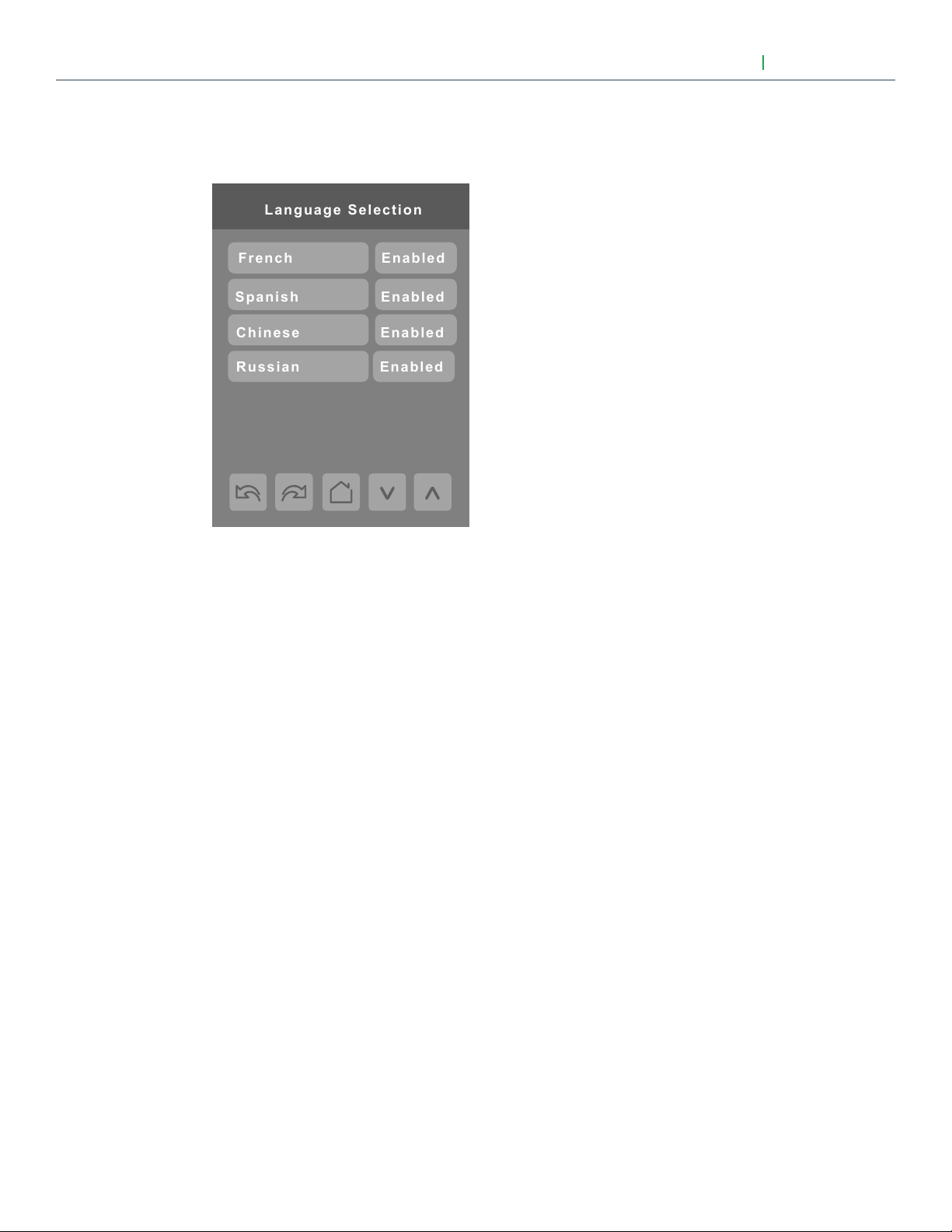
LANGUAGE SELECTION
User Interface Guide
VTR8300 Series
All languages are enabled by default, which means that they will be accessible to users cycling through languages on the
display settings menu screen. To change the language selection settings, touch a language on the screen and then use the
arrow buttons to disable or enable it. The English language is always enabled.
Viconics Technologies Inc. I Sma ll Building S ystems I 9245 Langelier Blvd. Saint- Leonard, Quebec, Canada, H1P 3K9 I +1 514 321 5660 I ww w.viconics.com
028-6045 -01 April 2014
© 2014 Viconics Technologies. All rights reserved.
 Loading...