

Page 1
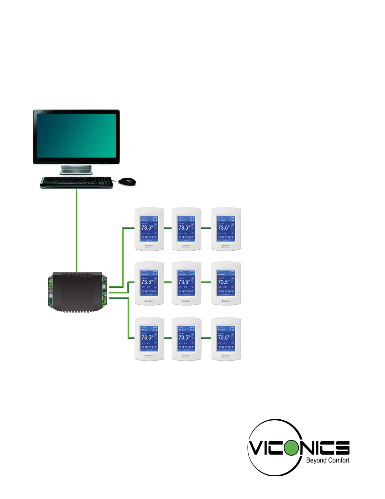
VT8600 Series BACnet Integration
Rooftop Unit and Indoor Air Quality Controller
Commercial and Lodging HVAC Applications
BACnet
CONTROLLER
Page 2
2
VT8600 SERIES BACNET COMPATIBILITY SPECIFICATIONS
Note: This document contains BACnet compatibility specifications of the Viconics VT8600 Room Controllers. The document follows the BACnet PICS format,
although Viconics products have not yet been BTL certified as of November 2014
Vendor Name: Viconics
Supported BACnet® Services: The BACnet® communicating controller meets
all requirements for designation as an Application Specific Controller (B-ASC). The
BACnet controller supports the following BACnet Interoperability Building Blocks
(BIBBs).
Application Service Designation
Data Sharing-COV-B DS-COV-B
Data Sharing – Read Property - B DS-RP-B
Data Sharing – Read Property Multiple - B DS-RPM-B
Data Sharing – Write Property - B DS-WP-B
Data Sharing - Write Property Multiple Service - B DS-WPM-B
VT8600 Series BACnet® Integration Manual
Device Management - Time Synchronization - B DM-TS-B
Device Management - Device Communication Control - B DM-DCC-B
Device Management – Dynamic Device Binding - B DM-DDB-B
Device Management – Dynamic Object Binding - B DM-DOB-B
Scheduling-Internal-B SCHED-I-B
Note: The controller does not support segmented requests or responses.
VT8600
Viconics Technologies Inc. | 9245 Langelie r Blvd. | St.-Leonard | Quebec | Canada | H1P 3K9 | Tel: ( 514) 321-5660 | Fa x : ( 514) 32 1- 4150
028-0437-00 www.viconics.com | sales@viconics.com March 2015
© 2015 Viconics Technologies Inc. All rights reserved.
Page 3

DEVICE OBJECTS TABLE
VT8600 Series BACnet® Integration Manual
3
Object Name
Type and
Instance
VT8600U5X00B Device
Object Property Controller Parameter
Object_Identifier
Property 75 (R,W)
Object_Name
Property 77 (R,W)
Model Name
Property 70 (R)
Firmware Revision
Property 44 (R)
Protocol Version
Property 98 (R)
Protocol Revision
Property 139 (R)
Max ADPU Length
Property 62 (R)
ADPU Timeout
Property 10 (R)
ApplicationSoftware-Version
Property 12 (R)
Max_Master (R,W)
Unique ID number of a device on a network
Unique name of a device on a network
Controller model number
Current BACnet
Current BACnet
®
firmware revision used by controller
®
firmware protocol version
Default is Version 1
®
Current BACnet
firmware protocol revision
Default is Version 2
Maximum ADPU Length accepted
Default is 480
ADPU timeout value
Default is 3000 ms
Controller base application software version
Default is based on current released version
Maximum master devices allowed to be part of
network.
0 to 127, default is 127
Description
Property 28 (R,W)
Location
Property 58 (R,W)
Local Date
Property 56 (R)
Local Time
Property 57 (R)
Viconics Technologies Inc. | 9245 Langelie r Blvd. | St.-Leonard | Quebec | Canada | H1P 3K9 | Tel: ( 514) 321-5660 | Fa x : ( 514) 32 1- 4150
028-0437-00 www.viconics.com | sales@viconics.com March 2015
String of printable characters
(Same as "Long Screen Message" CSV2)
String of printable characters
(Same as "Short Screen Message" CSV1)
Indicates date to best of device knowledge
Indicated time of day best of the device knowledge
© 2015 Viconics Technologies Inc. All rights reserved.
Page 4

4
ANALOG OBJECT PROPERTIES
Object Type
Read/Write Settings
Input
AI
Output
AO
VT8600 Series BACnet® Integration Manual
Object Property Controller Parameter
Values
AV
Read Only Read Only Read Only
Read Only Read Only Read Only
Read Only Read Only Read Only
Read Only Read Only Read Only
Read / Write Read / Write Read / Write
Read / Write* Read / Write Read / Write
N/A Read Only Read Only
Read Only Read Only Read Only
N/A Read Only Read / Write
Read Only Read Only Read Only
Event State
Property 36
Object Identifier
Property 75
Object Name
Property 77
Object Type
Property 79
Out of Service
Property 81
Present Value
Property 85
Priority Array
Property 87
Reliability
Property 103
Relinquish Default
†
Property 104
Status Flags
Property 111
Indicates if object has an active event state associated
with it
Unique ID number of an object on a network
Unique name of an object on a network
Indicates membership in a particular object type class
Indicates whether (TRUE/FALSE) the physical input
object represents is not in service
Contains values of all properties specified
Read-only array of prioritized values
Indicates if Present_Value is "reliable"
Default value used for Present_Value when values in
Priority_Array have a NULL value
Represents flags that indicate general health of life
safety point object
Read Only Read Only Read Only
N/A Read Only N/A
N/A Read Only N/A
Units
Property 177
Hight Limit
Property 1101
Low Limit
Property 1100
Indicates measurement units of Present_Value
Specifies a limit Present_Value must exceed before an
event is generated
Specifies a limit Present_Value must fall below before
an event is generated
N/A = Not Applicable, property not used for objects of that type
* The Present_Value is only writeable when Out_Of_Service is TRUE.
† Relinquish default is Read Only for AV100+
Viconics Technologies Inc. | 9245 Langelie r Blvd. | St.-Leonard | Quebec | Canada | H1P 3K9 | Tel: ( 514) 321-5660 | Fa x : ( 514) 32 1- 4150
028-0437-00 www.viconics.com | sales@viconics.com March 2015
© 2015 Viconics Technologies Inc. All rights reserved.
Page 5

BINARY OBJECT PROPERTIES
Object Type
Read/Write Settings
Input
BI
Output
BO
VT8600 Series BACnet® Integration Manual
Values
BV
5
Object Property Controller Parameter
Read Only Read Only Read Only
Read Only Read Only Read Only
Read Only Read Only Read Only
Read Only Read Only Read Only
Read Only Read Only Read Only
Read Only Read Only Read Only
Read / Write Read / Write Read / Write
Read Only Read / Write N/A
Read / Write Read / Write Read / Write
Active Text
Property 4
Event State
Property 36
Inactive Text
Property 46
Object Identifier
Property 75
Object Name
Property 77
Object Type
Property 79
Out of Service
Property 81
Polarity
Property 84
Present Value
Property 85
Characterizes intended effect of the ACTIVE state of
Present_Value property
Indicates if object has an active event state associated
with it
Characterizes intended effect of INACTIVE state of
Present_Value property
Unique ID number of a device on a network
Unique name of a device on a network
Indicates membership in a particular object type class
Indicates whether (TRUE/FALSE) physical input object
represents is not in service
Indicates relationship between physical state of input and
Present_Value
Contains values of all properties specified
Read Only Read Only Read Only
N/A Read Only Read Only
Read Only Read Only Read Only
Priority Array
Property 87
Relinquish Default
Property 104
Status Flags
Property 111
Read-only array of prioritized values
Default value to be used for Present_Value when values in
Priority_Array have a NULL value
Represents flags that indicate general health of life safety
point object
N/A = Not Applicable, property not used for objects of that type
Viconics Technologies Inc. | 9245 Langelie r Blvd. | St.-Leonard | Quebec | Canada | H1P 3K9 | Tel: ( 514) 321-5660 | Fa x : ( 514) 32 1- 4150
028-0437-00 www.viconics.com | sales@viconics.com March 2015
© 2015 Viconics Technologies Inc. All rights reserved.
Page 6

6
MULTISTATE OBJECT PROPERTIES
Object Type
Read/Write Settings
Inputs
MSI
Values
MV
VT8600 Series BACnet® Integration Manual
Object Property Controller Parameter
Read Only Read Only
Read Only Read Only
Read Only Read Only
Read Only Read Only
Read Only Read Only
Read / Write Read / Write
Read / Write* Read / Write
N/A Read Only
N/A Read / Write
Read Only Read Only
Event State
Property 36
Number of States
Property 74
Object Identifier
Property 75
Object Name
Property 77
Object Type
Property 79
Out of Service
Property 81
Present Value
Property 85
Priority Array
Property 87
Relinquish Default
Property 104
State Text
Property 110
Indicates if object has an active event state associated
with it
Defines number of states Present_Value may have
Unique ID number of a device on a network
Unique name of a device on a network
Indicates membership in a particular object type class
Indicates whether (TRUE/FALSE) physical input object
represents is not in service
Contains values of all properties specified
Indicates relationship between physical state of input
and Present_Value
Default value used for Present_Value when values in
Priority_Array have a NULL value
Represents descriptions of all possible states of
Present_Value
Read Only Read Only
Status Flags
Property 111
Represents flags that indicate general health of life
safety point object
N/A = Not Applicable, property not used for objects of that type
*The Present_Value is only writeable when Out_Of_Service is TRUE.
Viconics Technologies Inc. | 9245 Langelie r Blvd. | St.-Leonard | Quebec | Canada | H1P 3K9 | Tel: ( 514) 321-5660 | Fa x : ( 514) 32 1- 4150
028-0437-00 www.viconics.com | sales@viconics.com March 2015
© 2015 Viconics Technologies Inc. All rights reserved.
Page 7

VT8600 Series BACnet® Integration Manual
CSV OBJECT PROPERTIES
Read/Write Object Property Controller Parameter
7
Read Only
Read Only
Read Only
Read Only
Read / Write
Read Only
Event State
Property 36
Object Identifier
Property 75
Object Name
Property 77
Object Type
Property 79
Present Value
Property 85
Status Flags
Property 111
Indicates object has an active event state associated
with it
Unique ID number of a device on a network
Unique name of a device on a network
Indicates membership in a particular object type class
Contains values of all properties specified
Represents flags that indicate general health of life
safety point object
PG OBJECT PROPERTIES
Read/Write Object Property Controller Parameter
String of printable characters whose content is not
restricted. Contains the LUA program script (max size
= 480 bytes)
Read / Write
Description
Property 28
Read Only
Read Only
Read Only
Read Only
Read Only
Read Only
Write Only
Read Only
Read Only
Read Only
Viconics Technologies Inc. | 9245 Langelie r Blvd. | St.-Leonard | Quebec | Canada | H1P 3K9 | Tel: ( 514) 321-5660 | Fa x : ( 514) 32 1- 4150
028-0437-00 www.viconics.com | sales@viconics.com March 2015
Description Of Halt
Property 29
Instance Of
Property 48
Object Identifier
Property 75
Object Name
Property 77
Object Type
Property 79
Out Of Service
Property 81
Program Change
Property 90
Program State
Property 92
Reason For Halt
Property 100
Status Flags
Property 111
Describes the reason why a program has been halted
Text is also displayed in the HMI debug log
Local name of the application program being
executed by this process
Unique ID number of an object on a network
Unique name of an object on a network
Indicates membership in a particular object type class
Indicates whether (TRUE/FALSE) the process this
object represents is not in service
Used to request changes to the operating state of the
program. Writing to property affects all 10 PG objects
Current logical state of all 10 PG objects executing
application programs
If program halts, this property reflects the reason for
halt for all 10 PG objects
Represents flags that indicate general health of life
safety point object
© 2015 Viconics Technologies Inc. All rights reserved.
Page 8

8
CAL OBJECT PROPERTIES
Read/Write Object Property Controller Parameter
VT8600 Series BACnet® Integration Manual
Read / Write
Read Only
Read Only
Read Only
Read Only
Date List
Property 23
Object Identifier
Property 75
Object Name
Property 77
Object Type
Property 79
Present Value
Property 85
List of calender entries.
Unique ID number of an object on a network
Unique name of an object on a network
Indicates membership in a particular object type class
This property is TRUE when
current date matches an entry.
SCH OBJECT PROPERTIES
Read/Write Object Property Controller Parameter
Read Only
Read / Write
Read Only
Effective Period
Property 32
Exception Schedule
Property 38
Object Identifier
Property 75
Range of dates within which the Schedule object is
active. All dates are in range, so always Effective
Sequence of schedule actions that takes precedence
over normal behavior on a specific day or days. By
default, this property refers to the calendar.
Unique ID number of an object on a network
Read Only
Read Only
Read / Write
Read / Write
Read Only
Read Only
Read / Write
Read Only
Object Name
Property 77
Object Type
Property 79
Present Value
Property 85
Out Of Service
Property 81
Reliability
Property 103
Status Flags
Property 111
Weekly Schedule
Property 123
Schedule Default
Property 174
Unique name of an object on a network
Indicates membership in a particular object type class
Contains the current value of the schedule
(0:unoccupied, 1:occupied)
Only writeable when Out Of Service is TRUE
Indicates whether (TRUE/FALSE) the internal
calculations of the schedule object are used to
determine the value of the Present Value property
Indicates if Present Value is "reliable"
Represents flags that indicate general health of life
safety point object
7 elements that describe the sequence of schedule
actions for each day of the week.
Default value to be used when no other scheduled
value is in effect. Always Unoccupied
Viconics Technologies Inc. | 9245 Langelie r Blvd. | St.-Leonard | Quebec | Canada | H1P 3K9 | Tel: ( 514) 321-5660 | Fa x : ( 514) 32 1- 4150
028-0437-00 www.viconics.com | sales@viconics.com March 2015
© 2015 Viconics Technologies Inc. All rights reserved.
Page 9

VT8600 Series BACnet® Integration Manual
PROPERTY VALUE RANGE RESTRICTIONS FOR AV OBJECTS
Object name Object Type Instance
User HMI AV 2 0 11 0
Low Backlight AV 3 0% 100% 60%
Night Backlight AV 4 0% 100% 5%
Calibrate Temperature Sensor AV 7 - 5°F(2.5°C) 0°F (0°C)
COM Address AV 10 0 254 254
ZigBee PAN ID AV 11 0 1000 0
ZigBee channel AV 12 0 25 10
ZigBee Short Address AV 13 -32768 32767 0
ZigBee IEEE Address AV 14 0 32767 0
BACnet Stack Poll Rate AV 16 1 5 4
Discharge Low Limit AV 20 35°F (1.5°C) 65°F (18°C) 45°F (7°C)
Minimum Fresh Air AV 21 0 CFM 20000 CFM 0 CFM
Maximum Fresh Air AV 22 0 CFM 20000 CFM 0 CFM
Minimum CO2 AV 23 0 ppm 2000 ppm 800 ppm
Maximum CO2 AV 24 0 ppm 2000 ppm 1200 ppm
Lua Parameter A AV 25 -32768 32767 0
Lua Parameter B AV 26 -32768 32767 0
Lua Parameter C AV 27 -32768 32767 0
Lua Parameter D AV 28 -32768 32767 0
Lua Parameter E AV 29 -32768 32767 0
Lua Parameter F AV 30 -32768 32767 0
Occupied Heat Setpoint AV 39 40°F (4.5°C) 90°F (32°C) 72°F (22°C)
Occupied Cool Setpoint AV 40 54°F (12°C) 100°F (37.5°C) 75°F (24°C)
Standby Heat Setpoint AV 41 40°F (4.5°C) 90°F (32°C) 69°F (21°C)
Standby Cool Setpoint AV 42 54°F (12°C) 100°F (37.5°C) 78°F (26°C)
Unoccupied Heat Setpoint AV 43 40°F (4.5°C) 90°F (32°C) 62°F (16.5°C)
Unoccupied Cooling Setpoint AV 44 54°F (12°C) 100°F (37.5°C) 80°F (26.5°C)
Default Heating Setpoint AV 45 65°F (18°C) 80°F (26.5°C) 72°F (22°C)
Standby Temperature Differential AV 46 10°F (5.5°C) 50°F (28°C) 40°F (22°C)
Main Password AV 56 0 9999 N/A
User Password AV 57 0 9999 0
Minimum
Range Value
Maximum
Range Value
Default Value
9
Viconics Technologies Inc. | 9245 Langelie r Blvd. | St.-Leonard | Quebec | Canada | H1P 3K9 | Tel: ( 514) 321-5660 | Fa x : ( 514) 32 1- 4150
028-0437-00 www.viconics.com | sales@viconics.com March 2015
© 2015 Viconics Technologies Inc. All rights reserved.
Page 10

10
VT8600 Series BACnet® Integration Manual
PROPERTY VALUE RANGE RESTRICTIONS FOR AV OBJECTS
Object Name Object Type Instance
Minimum
Range Value
Heating Setpoint Limit AV 58 40°F (4.5°C) 90°F (32°C) 90°F (32°C)
Cooling Setpoint Limit AV 59 54°F (12°C) 100°F (37.5°C) 54°F (12°C)
Temporary Occupancy Time AV 62 0H 24H 2H
Minimum Deadband AV 63 2°F (1°C) 5°F (2.5°C) 2°F (1°C)
Proportional Band AV 65 3°F (1.2°C) 10°F (5.6°C) 3°F (1.2°C)
Standby time AV 67 5H 24H 5H
Unoccupied Time AV 68 0H 24H 0H
Calibrate Outside Temp. Sensor AV 74 - 5°F(2.5°C) 0°F (0°C)
Number of Cooling Stages AV 75 1 2 2
Power-up Delay AV 76 10 s 120 s 10 s
Economizer Minimum Position AV 78 0% 100% 0%
Economizer Maximum Position AV 81 0% 100% 100%
Heating CPH AV 84 3 8 4
Cooling CPH AV 85 3 8 4
Anti Short Cycle Timer AV 86 0 min 5 min 2 min
Number of Heating Stages AV 87 0 2 2
Heating Demand Limit AV 88 0% 100% 0%
Cooling Demand Limit AV 89 0% 100% 0%
Heat Lock AV 91 -15°F (-26°C) 120°F (49°C) 120°F (49°C)
Cool Lock AV 93 -40°F (-40°C) 125°F (52°C) -40°F (-40°C)
Supply Air Setpoint AV 94 50°F (10°C) 90°F (32°C) 55°F (13°C)
Changeover Setpoint AV 95 14°F (-10°C) 70°F (21°C) 55°F (13°C)
Fresh Air Range Upper Limit AV 96 0 ft
3
Minimum Supply Heat AV 97 50°F (10°C) 72°F (22°C) 64°F (18°C)
Supply Heat Lockout AV 98 -15°F (-26°C) 120°F (49°C) 32°F (0°C)
Discharge High Limit AV 99 70°F (21°C) 150°F (65.5°C) 120°F (49°C)
Room Temperature AV 100 -40°F (-40°C) 122°F (50°C) N/A
Outdoor Temperature AV 101 -40°F (-40°C) 122°F (50°C) N/A
Supply Temperature AV 102 -40°F (-40°C) 122°F (50°C) N/A
CO2 Level AV 106 0 ppm 2000 ppm 0 ppm
Air Flow Level AV 107 0 ft
3
UI19 Status AV 108 0% 100% 0%
Maximum
Range Value
20000 ft
20000 ft
3
3
Default Value
3
0 ft
3
0 ft
Viconics Technologies Inc. | 9245 Langelie r Blvd. | St.-Leonard | Quebec | Canada | H1P 3K9 | Tel: ( 514) 321-5660 | Fa x : ( 514) 32 1- 4150
028-0437-00 www.viconics.com | sales@viconics.com March 2015
© 2015 Viconics Technologies Inc. All rights reserved.
Page 11

VT8600 Series BACnet® Integration Manual
PROPERTY VALUE RANGE RESTRICTIONS FOR AI OBJECTS
11
Object Name Object Type Instance
Light Sensor Level AI 2 0 30000 N/A
Rem. Sensor (UI 20) AI 5 0 4095 0
Outdoor Remote Input (UI 21) AI 7 0 4095 0
Supply Temp Input (UI 22) AI 8 0 4095 0
UI 24 Raw Value AI 9 0 4095 0
UI 19 Raw Value AI 31 0 4095 0
Wireless Zone 1 IEEE address AI 210 0 32767 0
Wireless Zone 2 IEEE address AI 220 0 32767 0
Wireless Zone 3 IEEE address AI 230 0 32767 0
Wireless Zone 4 IEEE address AI 240 0 32767 0
Wireless Zone 5 IEEE address AI 250 0 32767 0
Wireless Zone 6 IEEE address AI 260 0 32767 0
Wireless Zone 7 IEEE address AI 270 0 32767 0
Wireless Zone 8 IEEE address AI 280 0 32767 0
Wireless Zone 9 IEEE address AI 290 0 32767 0
Wireless Zone 10 IEEE address AI 300 0 32767 0
Minimum
Range Value
Maximum
Range Value
Default Value
PROPERTY VALUE RANGE RESTRICTIONS FOR AO OBJECTS
Object Name Object Type Instance
PI Heating Demand AO 21 0% 100% N/A
PI Cooling Demand AO 22 0% 100% N/A
Econo. Demand AO 23 0% 100% N/A
Analog Output Heat Demand AO 24 0% 100% N/A
UO 11 Analog Output AO 123 0 10 0
UO 12 Analog Output AO 124 0 10 0
UO 9 Analog Output AO 125 0 10 0
UO 10 Analog Output AO 126 0 10 0
Minimum
Range Value
Maximum
Range Value
Default Value
PROPERTY VALUE RANGE RESTRICTIONS FOR BI OBJECTS
Object Name Object Type Instance
UI 16 Binary Input BI 29 Deactivated Activated Deactivated
UI 17 Binary Input BI 30 Deactivated Activated Deactivated
UI 19 Binary Input BI 91 Deactivated Activated Deactivated
Minimum
Range Value
Maximum
Range Value
Default Value
Viconics Technologies Inc. | 9245 Langelie r Blvd. | St.-Leonard | Quebec | Canada | H1P 3K9 | Tel: ( 514) 321-5660 | Fa x : ( 514) 32 1- 4150
028-0437-00 www.viconics.com | sales@viconics.com March 2015
© 2015 Viconics Technologies Inc. All rights reserved.
Page 12

12
VT8600 Series BACnet® Integration Manual
PROPERTY VALUE RANGE RESTRICTIONS FOR BO OBJECTS
Object Name Object Type Instance
G Fan Status BO 25 Off On Off
Y1 Status BO 26 Off On Off
Y2 Status BO 27 Off On Off
W1 Status BO 28 Off On Off
W2 Status BO 29 Off On Off
UO 10 Binary Output BO 94 Off On Off
BO 1 Auxiliary Binary Output BO 98 Off On Off
UO 11 Binary Output BO 101 Off On Off
UO 12 Binary Output BO 102 Off On Off
Minimum
Range Value
Maximum
Range Value
Default Value
PROPERTY VALUE RANGE RESTRICTIONS FOR BV OBJECTS
Object Name Object Type Instance
Door Contact Status BV 1 Closed Open Closed
Door Contact Installed BV 2 No Ye s No
Window Contact Status BV 3 Closed Opened Closed
Window Contact Installed BV 4 No Ye s No
Low Battery Alarm BV 5 Off On Off
Force High Backlight BV 6 Off On Off
Display Long Screen Message BV 7 Off On Off
Exception Status BV 10 Off On Off
PIR Local Motion BV 32 Off On Off
Window Alarm BV 35 Off On Off
Filter Alarm BV 36 Off On Off
Service alarm BV 37 Off On Off
Fan Lock Alarm BV 39 Off On Off
Smart Recovery BV 40 Off On Off
CO2 Alarm BV 41 Off On Off
Air Alarm BV 42 Off On Off
Frost Protection Alarm BV 43 Off On Off
ZigBee PIR Sensor Installed BV 200 Off On Off
Zigbee Sensor Motion BV 201 Off On Off
Minimum
Range Value
Maximum
Range Value
Default Value
PROPERTY VALUE RANGE RESTRICTIONS FOR CSV OBJECTS
Object Name Object Type Instance
String of printable characters.
Short Screen Message CSV 1
Long Screen Message CSV 2
Viconics Technologies Inc. | 9245 Langelie r Blvd. | St.-Leonard | Quebec | Canada | H1P 3K9 | Tel: ( 514) 321-5660 | Fa x : ( 514) 32 1- 4150
028-0437-00 www.viconics.com | sales@viconics.com March 2015
(Same as Location Property 58 (R,W))
* Not saved in EEPROM, this info will be lost after a power loss.
String of printable characters.
(Same as Description Property 28 (R,W))
* Not saved in EEPROM, this info will be lost after a power loss.
Parameters
© 2015 Viconics Technologies Inc. All rights reserved.
Page 13

VT8600 Series BACnet® Integration Manual
PROPERTY VALUE RANGE RESTRICTIONS FOR MV OBJECTS
Object Name Object ID Instance Index Text Default Value
Long Message Background Color MV 1
HMI Color MV 2
Main Display MV 3
Display Language MV 4
Time Format MV 5
Network Units MV 6
Network Language MV 7
BACnet Baud Rate MV 8
Occupancy Command MV 10
Standby Mode Config MV 11
1 White
2 Green
3 Blue
4 Grey
5 Dark Grey
6 Default
7 Red
1 White
2 Green
3 Blue
4 Grey
5 Dark Grey
1 Temperature
2 Setpoint
1 English
2 French
3 Spanish
4 Chinese
1 AM-PM
2 24 Hours
1 SI
2 Imperial
1 English
3 Spanish
1 9600
2 19200
3 38400
4 57600
5 76800
6 115200
7 Auto
1 Local Occupancy
3 Unoccupied
1 Absolute
2 Offset
13
White
Green
Temperature
English
AM-PM
SI
English2 French
Auto
Local Occupancy2 Occupied
Absolute
Viconics Technologies Inc. | 9245 Langelie r Blvd. | St.-Leonard | Quebec | Canada | H1P 3K9 | Tel: ( 514) 321-5660 | Fa x : ( 514) 32 1- 4150
028-0437-00 www.viconics.com | sales@viconics.com March 2015
© 2015 Viconics Technologies Inc. All rights reserved.
Page 14

14
PROPERTY VALUE RANGE RESTRICTIONS FOR MV OBJECTS
Object Name Object ID Instance Index Text Default Value
System Mode MV 16
Fan Mode MV 17
Use Standby Screen MV 32
UI 16 Configuration MV 46
UI 17 Configuration MV 47
UI 19 Configuration MV 49
Temperature Scale MV 51
Frost Protection MV 55
Setpoint Function MV 58
Smart Recovery MV 71
Econo Config MV 72
Schedule menu MV 73
Mechanical Cooling Allowed MV 79
BO1 Auxiliary Output Config MV 92
Fan Control in Heating Mode MV 95
1 Off
2 Auto
3 Cool
4 Heat
1 On
3 Smart
1 No
2 Yes
1 None
2 Rem NSB
3 Motion NO
4 Motion NC
5 Window
1 None
3 Override
1 None
2 CO
2
1 °C
2 °F
1 Off
2 On
1 Dual Stp
2 Attach Stp
1 Off
2 On
1 Off
2 On
1 Disabled
2 Enabled
1 Off
2 On
1 NO
2 NC
1 On
3 Off-All
VT8600 Series BACnet® Integration Manual
Heat
Auto2 Auto
No
None
None2 Door Dry
None
°C
Off
Attach Stp
Off
Off
Enabled
Off
NO
On2 Off-Auto
Viconics Technologies Inc. | 9245 Langelie r Blvd. | St.-Leonard | Quebec | Canada | H1P 3K9 | Tel: ( 514) 321-5660 | Fa x : ( 514) 32 1- 4150
028-0437-00 www.viconics.com | sales@viconics.com March 2015
© 2015 Viconics Technologies Inc. All rights reserved.
Page 15

VT8600 Series BACnet® Integration Manual
PROPERTY VALUE RANGE RESTRICTIONS FOR MV OBJECTS
Object Name Object ID Instance Index Text Default Value
1 Analog
UO 9 Configuration MV 96
UO 10 Configuration MV 97
UO 11 Configuration MV 98
UO 12 Configuration MV 99
French MV 101
Spanish MV 102
Chinese MV 103
Russian MV 104
Occupancy Source MV 110
Mode button MV 111
Wireless Zone 1 Set Function MV 210
Wireless Zone 2 Set Function MV 220
Wireless Zone 3 Set Function MV 230
Viconics Technologies Inc. | 9245 Langelie r Blvd. | St.-Leonard | Quebec | Canada | H1P 3K9 | Tel: ( 514) 321-5660 | Fa x : ( 514) 32 1- 4150
028-0437-00 www.viconics.com | sales@viconics.com March 2015
2 Binary
3 Relay RC
4 Relay RH
1 Analog
3 Relay RC
1 Analog
2 Binary
1 Analog
2 Binary
1 Disabled
2 Enabled
1 Disabled
2 Enabled
1 Disabled
2 Enabled
1 Disabled
2 Enabled
1 Motion
2 Schedule
1 Normal
2 Off-Auto
1 None
2 Window
3 Door
4 Motion
5 Status
6 Remove
1 None
2 Window
3 Door
4 Motion
5 Status
6 Remove
1 None
2 Window
3 Door
4 Motion
5 Status
6 Remove
Relay RH
Analog2 Binary
Analog
Analog
Enabled
Enabled
Enabled
Enabled
Motion
Normal
None
None
None
15
© 2015 Viconics Technologies Inc. All rights reserved.
Page 16

16
PROPERTY VALUE RANGE RESTRICTIONS FOR MV OBJECTS
Object Name Object Type Instance Index Text Default Value
Wireless Zone 4 Set Function MV 240
Wireless Zone 5 Set Function MV 250
Wireless Zone 6 Set Function MV 260
Wireless Zone 7 Set Function MV 270
Wireless Zone 8 Set Function MV 280
Wireless Zone 9 Set Function MV 290
1 None
2 Window
3 Door
4 Motion
5 Status
6 Remove
1 None
2 Window
3 Door
4 Motion
5 Status
6 Remove
1 None
2 Window
3 Door
4 Motion
5 Status
6 Remove
1 None
2 Window
3 Door
4 Motion
5 Status
6 Remove
1 None
2 Window
3 Door
4 Motion
5 Status
6 Remove
1 None
2 Window
3 Door
4 Motion
5 Status
6 Remove
VT8600 Series BACnet® Integration Manual
None
None
None
None
None
None
Viconics Technologies Inc. | 9245 Langelie r Blvd. | St.-Leonard | Quebec | Canada | H1P 3K9 | Tel: ( 514) 321-5660 | Fa x : ( 514) 32 1- 4150
028-0437-00 www.viconics.com | sales@viconics.com March 2015
© 2015 Viconics Technologies Inc. All rights reserved.
Page 17

VT8600 Series BACnet® Integration Manual
PROPERTY VALUE RANGE RESTRICTIONS FOR MV OBJECTS
Object Name Object Type Instance Index Text Default Value
1 None
2 Window
Wireless Zone 10 Set Function MV 300
3 Door
4 Motion
5 Status
6 Remove
None
PROPERTY VALUE RANGE RESTRICTIONS FOR MSI OBJECTS
Object Name Object Type Instance Index Text Default Value
17
BACnet Status MSI 1
ZigBee Status MSI 2
Effective Occupancy MSI 33
Wireless Zone 1 Status MSI 210
Wireless Zone 1 Battery MSI 211
Wireless Zone 1 Paired MSI 212
Wireless Zone 2 Status MSI 220
1 Offline
2 Online
1 Not Detected
2 Power On
3 No Network
4 Joined
5 Online
1 Occupied
2 Unoccupied
3 Override
4 Standby
1 None
2 Closed
3 Opened
4 Motion
5 No Motion
1 None
3 Low
1 No
3 Invalid
1 None
2 Closed
3 Opened
4 Motion
5 No Motion
Offline
N/A
Occupied
None
None2 Normal
No2 Yes
None
Viconics Technologies Inc. | 9245 Langelie r Blvd. | St.-Leonard | Quebec | Canada | H1P 3K9 | Tel: ( 514) 321-5660 | Fa x : ( 514) 32 1- 4150
028-0437-00 www.viconics.com | sales@viconics.com March 2015
© 2015 Viconics Technologies Inc. All rights reserved.
Page 18

18
VT8600 Series BACnet® Integration Manual
PROPERTY VALUE RANGE RESTRICTIONS FOR MSI OBJECTS
Object Name Object Type Instance Index Text Default Value
1 None
Wireless Zone 2 Battery MSI 221
Wireless Zone 2 Paired MSI 222
Wireless Zone 3 Status MSI 230
Wireless Zone 3 Battery MSI 231
Wireless Zone 3 Paired MSI 232
Wireless Zone 4 Status MSI 240
Wireless Zone 4 Battery MSI 241
Wireless Zone 4 Paired MSI 242
Wireless Zone 5 Status MSI 250
Wireless Zone 5 Battery MSI 251
Wireless Zone 5 Paired MSI 252
3 Low
1 No
3 Invalid
1 None
2 Closed
3 Opened
4 Motion
5 No Motion
1 None
3 Low
1 No
2 Yes
3 Invalid
1 None
2 Closed
3 Opened
4 Motion
5 No Motion
1 None
3 Low
1 No
3 Invalid
1 None
2 Closed
3 Opened
4 Motion
5 No Motion
1 None
3 Low
1 No
3 Invalid
None2 Normal
No2 Ye s
None
None2 Normal
No
None
None2 Normal
No2 Ye s
None
None2 Normal
No2 Ye s
Viconics Technologies Inc. | 9245 Langelie r Blvd. | St.-Leonard | Quebec | Canada | H1P 3K9 | Tel: ( 514) 321-5660 | Fa x : ( 514) 32 1- 4150
028-0437-00 www.viconics.com | sales@viconics.com March 2015
© 2015 Viconics Technologies Inc. All rights reserved.
Page 19

VT8600 Series BACnet® Integration Manual
PROPERTY VALUE RANGE RESTRICTIONS FOR MSI OBJECTS
Object Name Object Type Instance Index Text Default Value
1 None
2 Closed
Wireless Zone 6 Status MSI 260
Wireless Zone 6 Battery MSI 261
Wireless Zone 6 Paired MSI 262
Wireless Zone 7 Status MSI 270
Wireless Zone 7 Battery MSI 271
Wireless Zone 7 Paired MSI 272
Wireless Zone 8 Status MSI 280
Wireless Zone 8 Battery MSI 281
Wireless Zone 8 Paired MSI 282
Wireless Zone 9 Status MSI 290
3 Opened
4 Motion
5 No Motion
1 None
2 Normal
3 Low
1 No
3 Invalid
1 None
2 Closed
3 Opened
4 Motion
5 No Motion
1 None
3 Low
1 No
3 Invalid
1 None
2 Closed
3 Opened
4 Motion
5 No Motion
1 None
3 Low
1 No
2 Yes
3 Invalid
1 None
2 Closed
3 Opened
4 Motion
5 No Motion
None
None
No2 Ye s
None
None2 Normal
No2 Ye s
None
None2 Normal
No
None
19
Viconics Technologies Inc. | 9245 Langelie r Blvd. | St.-Leonard | Quebec | Canada | H1P 3K9 | Tel: ( 514) 321-5660 | Fa x : ( 514) 32 1- 4150
028-0437-00 www.viconics.com | sales@viconics.com March 2015
© 2015 Viconics Technologies Inc. All rights reserved.
Page 20

20
VT8600 Series BACnet® Integration Manual
PROPERTY VALUE RANGE RESTRICTIONS FOR MSI OBJECTS
Object Name Object Type Instance Index Text Default Value
1 None
Wireless Zone 9 Battery MSI 291
Wireless Zone 9 Paired MSI 292
Wireless Zone 10 Status MSI 300
Wireless Zone 10 Battery MSI 301
Wireless Zone 10 Paired MSI 302
3 Low
1 No
3 Invalid
1 None
2 Closed
3 Opened
4 Motion
5 No Motion
1 None
3 Low
1 No
2 Yes
3 Invalid
None2 Normal
No2 Ye s
None
None2 Normal
No
PROPERTY VALUE RANGE RESTRICTIONS FOR PG OBJECTS
Object Name Object Type Instance
Lua Program 1 PG 1 Lua program code is recorded in the description field
Lua Program 2 PG 2 Lua program code is recorded in the description field
Lua Program 3 PG 3 Lua program code is recorded in the description field
Lua Program 4 PG 4 Lua program code is recorded in the description field
Lua Program 5 PG 5 Lua program code is recorded in the description field
Lua Program 6 PG 6 Lua program code is recorded in the description field
Lua Program 7 PG 7 Lua program code is recorded in the description field
Lua Program 8 PG 8 Lua program code is recorded in the description field
Lua Program 9 PG 9 Lua program code is recorded in the description field
Lua Program 10 PG 10 Lua program code is recorded in the description field
Parameters
PROPERTY VALUE RANGE RESTRICTIONS FOR SCH / CAL OBJECTS
Object Name Object Type Instance
Occupancy Schedule SCH 1
Occupancy Calendar CAL 1 Date, Range of dates, Weekend
7 days of the week, 3 occupied setpoint times & 3
unoccupied setpoint times alternating in fixed order.
Parameters
Viconics Technologies Inc. | 9245 Langelie r Blvd. | St.-Leonard | Quebec | Canada | H1P 3K9 | Tel: ( 514) 321-5660 | Fa x : ( 514) 32 1- 4150
028-0437-00 www.viconics.com | sales@viconics.com March 2015
© 2015 Viconics Technologies Inc. All rights reserved.
Page 21

VT8600 Series BACnet® Integration Manual
INTEGRATION – GLOBAL COMMANDS
The following figure shows which objects from the controller can be monitored and controlled from the BAS front-end.
Global Command Control Level Device Level
MS/TP
Network
21
BAS
Front End
All Devices
(All controllers)
Outdoor Temperature
Outdoor Temperature and HVAC plant current mode
Specific Devices
(Specific area controllers)
Schedule
Schedule
Outdoor Temperature
Restrict user access to controller
VT8600 Series
controller
Outdoor Temperature (AV101)
System mode (MV16)
Occupancy Command (MV10)
Fan Mode (MV17)
Occupied Heating Setpoint (AV39)
Unoccupied Heating Setpoint (AV43)
Occupied Cooling Setpoint (AV40)
Unoccupied Cooling Setpoint (AV44)
Main Password (AV56)
Room temperature for testing and override
Figure 1 : Global commands from a BAS front-end to a typical VT86xx series controller
Room Temperature (AV100)
Note: For information about integrating ZigBee wireless sensors with BACnet, refer to the
ZigBee Wireless Sensor Installation Guide.
Viconics Technologies Inc. | 9245 Langelie r Blvd. | St.-Leonard | Quebec | Canada | H1P 3K9 | Tel: ( 514) 321-5660 | Fa x : ( 514) 32 1- 4150
028-0437-00 www.viconics.com | sales@viconics.com March 2015
© 2015 Viconics Technologies Inc. All rights reserved.
Page 22

22
VT8600 Series BACnet® Integration Manual
VT8600U5X00B INTEGRATION –
GRAPHICAL USER INTERFACE OBJECTS
Objects typically used in a GUI:
• RoomTemperature(AV100)
• OccupiedandUnoccupiedHeatSetpoints
(AV39 and AV43)
• OccupiedandUnoccupiedCoolSetpoints
(AV40 and AV44)
• OutdoorTemperature(AV101)
• SupplyTemperature(AV102,ifavailable)
• OccupancyCommand(MV10)
• SystemMode(MV16)
• AuxiliaryOutputStatus(BO98)
• PIHeatingDemand(AO21)
• PICoolingDemand(AO22)
• WindowAlarm(BV35)
• FilterAlarm(BV36)
• ServiceAlarm(BV37)
Occupancy
System mode
Outdoor Temperature
Normal
PI Cool
0%
Filter Alarm
Figure-1 GUI Example - VT8600UXBXX
Occupied
Heat
o
42
F
Fan Status
On
Room Temperature
Occupied Heating Setpoint
Occupied Cooling Setpoint
Unoccupied Heating Setpoint
Unoccupied Cooling Setpoint
PI Heat
53%
Supply Temperature 42oF
o
71.2
F
o
71.0
F
o
73.0
F
o
62.0
F
o
82.0
F
Occupancy
System mode
Outdoor Temperature
Occupied
Cool
o
80
F
Supply Temperature (AI11)
PI Cooling 78%
Demand
65.2
Occupied Heating Setpoint
Occupied Cooling Setpoint
Unoccupied Heating Setpoint
Unoccupied Cooling Setpoint
Figure-2 GUI Example - VT8600UXBXX
o
F
PI Heating Demand
Room Temperature
53%
Supply Temperature 65.2
o
74.2
F
o
71.0
F
o
73.0
F
o
62.0
F
o
82.0
F
o
F
Viconics Technologies Inc. | 9245 Langelie r Blvd. | St.-Leonard | Quebec | Canada | H1P 3K9 | Tel: ( 514) 321-5660 | Fa x : ( 514) 32 1- 4150
028-0437-00 www.viconics.com | sales@viconics.com March 2015
© 2015 Viconics Technologies Inc. All rights reserved.
Page 23

VT8600 Series BACnet® Integration Manual
CONFIGURATION OBJECTS
If your BAS allows you to remove objects, Viconics recommends removing all configuration objects
once your setup is complete. This prevents unnecessary network
polling and traffic.
WIRING GUIDE
Overview
Viconics uses EIA-485 as the physical layer between their devices and supervisory controllers. A
"Device” represents any product with an active EIA-485 network connection, including Viconics and
non Viconics controllers.
A summary of network specifications are listed below.
Summary Specifications
Parameter Details
Media
Characteristic Impedance
Distributed capacitance
Maximum length per segment
Polarity
Multi-drop
Terminations
Network bias resistors
Maximum number of nodes per segment
Maximum number of nodes per network
Baud rate
Twisted pair 18 AWG, 22 AWG, or 24 AWG
(shielded recommended)
100-130 ohms
Less than 100 pF per meter (30 pF per foot)
1200 meters (4000 feet) Note: 18 AWG cable
Polarity sensitive
Daisy-chain (no T connections)
1. Devices are installed at both ends of the MS/TP
network: 120 Ohms resistor should be installed at each
end.
2. A device is installed at one end of the MS/TP network
and a third-party device is installed at the other end.
Install an End-Of-Line resistor value that matches the
third-party device instruction regarding the End-Of-Line
resistors.
3. Third-party devices are installed at both ends of
the MS/TP network. Follow the third-party device
instructions regarding the End-Of-Line resistors.
510 ohms per wire (maximum two sets per segment)
64 (Viconics devices only)
128
9600, 19200, 38400, 57600, 76800, 115200 (Auto detect)
23
Table : Summary of Specifications for a
Viconics Technologies Inc. | 9245 Langelie r Blvd. | St.-Leonard | Quebec | Canada | H1P 3K9 | Tel: ( 514) 321-5660 | Fa x : ( 514) 32 1- 4150
028-0437-00 www.viconics.com | sales@viconics.com March 2015
Viconics
EIA-485 Network
© 2015 Viconics Technologies Inc. All rights reserved.
Page 24

24
WIRING GUIDE
Cable Type
Viconics recommends the use of balanced 22-24 AWG twisted pair with a characteristic impedance of 100130 ohms and capacitance of 30 pF/ft or lower. A braided shield is also recommended.
Impedance
A value based on the inherent conductance, resistance, capacitance, and inductance that represent the
impedance of an infinitely long cable. The nominal impedance of the cable should be between 100 ohms and
120 ohms. Using 120 ohms results in a lighter load on the network.
Capacitance (pF/ft)
The amount of equivalent capacitive load of the cable (per foot basis). One factor limiting total cable length is
the capacitive load. Systems with long lengths benefit from using low capacitance cable (17pF/ft or lower).
NETWORK CONFIGURATION
EIA-485 networks use a daisy chain configuration. A daisy chain has only one main cable and every network
device is connected directly along its path.
VT8600 Series BACnet® Integration Manual
Figure 3 illustrates two improper network configurations and the proper daisy chain configuration.
Figure 3 : Three different network configurations: star, bus, and daisy chain. Only the daisy chain configuration is correct for an
EIA-485 network
Other methods of wiring an EIA-485 network may give unreliable and unpredictable results. There are no troubleshooting methods
for these types of networks. Site experimentation may be required with no guarantee of success. As a result, Viconics only supports daisy chain configurations.
Maximum Number of Devices
A maximum of 64 nodes are allowed on a single daisy-chain segment. A node is defined as any device (panel, zone,
or Repeater) connected to the RS485 network. Terminators do not count as a node.
Add the following to determine the number of nodes on a network:
•Onenodeforeachdevice,includingmainpanels
•Onenodeforeachrepeateronthechain
Viconics Technologies Inc. | 9245 Langelie r Blvd. | St.-Leonard | Quebec | Canada | H1P 3K9 | Tel: ( 514) 321-5660 | Fa x : ( 514) 32 1- 4150
028-0437-00 www.viconics.com | sales@viconics.com March 2015
© 2015 Viconics Technologies Inc. All rights reserved.
Page 25

VT8600 Series BACnet® Integration Manual
*NOTE: End Of Line resistors do not count as nodes.
25
EOL
Resistor
SC
Supervisory
EOL
Resistor
Controller
Node 1 Node 2 Node 3 Node 4 Node 5
Figure 4 : Exa mple Network - 5 Nodes
Figure 4 shows one node for the main SC panel and 4 for the controllers, for a total of 5 nodes. If there are
more than 64 devices, install repeaters to extend the network.
Maximum Cable Length
The maximum length of a chain is related to its transmission speed. The longer the chain, the slower the
speed. Using proper cable, the maximum length of an EIA-485 daisy chain is 4000-ft (1200 m). This only works
reliably for data rates up to 100,000 bps. Viconics maximum data rate is 76,800 bps.
network length of more than 4000 feet, repeaters are required to extend the network.
EIA-485 Repeaters
If you have more than 64 devices, or require a maximum network length of more than 4000 feet, repeaters are
required to extend the network.
If you require a maximum
End Of Line (EOL) Resistors
EOL
Resistor
EOL
Resistor
SC
Supervisory
Controller
EOL
Resistor
EOL
Resistor
EOL
Resistor
Repeater
Repeater
Repeater
Figure-5 Correct Repeater Use in an EIA-485 Network
EOL
Resistor
EOL
Resistor
EOL
Resistor
Viconics Technologies Inc. | 9245 Langelie r Blvd. | St.-Leonard | Quebec | Canada | H1P 3K9 | Tel: ( 514) 321-5660 | Fa x : ( 514) 32 1- 4150
028-0437-00 www.viconics.com | sales@viconics.com March 2015
© 2015 Viconics Technologies Inc. All rights reserved.
Page 26

26
13-COM +
14-COM -
VTR83xxA
Terminal Controller
13-COM +
14-COM -
VTR83xxA
Terminal Controller
To others
To others
The ideal configuration is to daisy chain the repeaters to the main panel. From each of these repeaters, a
separate daisy chain branches off. Figure 5 demonstrates a valid use of repeaters in an EIA-485 network.
Do not install repeaters in series as this may result in network reliability problems. Incorrect use of a repeater
in an EIA-485 network is illustrated below in Figure 6.
VT8600 Series BACnet® Integration Manual
SC
Supervisory
Controller
EOL
Resistor
Repeater
CAUTION:
DO NOT ADD A SECOND REPEATER IN SERIES
EOL
Resistor
Figure-6 Incorrect Repeater Use in an EIA-485 Network
EOL
Resistor
Repeater
EOL
Resistor
EOL
Resistor
MS/TP network must be properly terminated. For daisy chain configurations, you must install an EOL resistor
at each end of the daisy chain. Depending on your MSTP network configuration, the resistance value of the
EOL resistor may change. Viconics devices are installed at both ends of the MSTP network. Also, a 120 Ohm
resistor should be installed at each end.
A Viconics device is installed at one end of the MSTP network and a 3rd party device is installed at the other
end. Make sure you install an End-Of-Line resistor value that matches the 3rd party devices instructions
regarding its EOL resistor value. Any 3rd party devices are installed at both ends of the MSTP network.
Network Adapter
BACnet® Communication Wiring (if applicable)
Figure-7 MS/TP Connections
Viconics Technologies Inc. | 9245 Langelie r Blvd. | St.-Leonard | Quebec | Canada | H1P 3K9 | Tel: ( 514) 321-5660 | Fa x : ( 514) 32 1- 4150
028-0437-00 www.viconics.com | sales@viconics.com March 2015
© 2015 Viconics Technologies Inc. All rights reserved.
Page 27

VT8600 Series BACnet® Integration Manual
The polarity of the connection to the cable is important. From one module to the other it is important that the
same colored wire be connected to “plus” or “+” and the other colored wire be connected to the “minus” or
”-“. Figure 7 shows the proper MS/TP connections.
NOTE: The Ref terminal should NEVER be used to wire shields. The 2 shields from each feed of the network
connection to a controller should be wired
any accidental connection to the ground.
together in the back of the controller and properly protected to prevent
The joined shield connection should then be grounded at a SINGLE point on the whole segment. More than
one ground connection to a shielded wire may induce ground loop noises and affect communication.
DEFAULT DEVICE NAME AND ID
Default Device Name set to Model number – MAC where:
•MACisthecurrentMACaddressofthedevice.
•ModelnumberisViconicspartnumber.
The device name upgrades as soon as there is a change to the device MAC address.
The Device Name and Device ID properties are writable. Both properties can be renamed from any BACnet®
network management tool as long as the tool itself can write to these properties.
27
VT8600UXBXX Models
Default Device ID is set to: 86000 + MAC where MAC is the current MAC address of the device.
The device ID upgrades as soon as there is a change to the device’s MAC. For example, when a VT8600 con-
troller with a MAC address of 63 is connected to a network, its default Device ID is 86063.
INTEGRATING VICONICS DEVICES ON A BACNET MS/TP NETWORK
Before doing any BACnet® integration, make sure you refer to a Viconics PICS document (Protocol Implementation
Conformance Statement). The PICS document lists all the BACnet® Services and Object types supported by a
device. You can find the document at www.viconics.com.
Viconics devices do not support the COV service. COV reporting allows an object to send out notices when its
Present-Value property is incremented by a pre-defined value. Since this is not supported at Viconics, special
attention should be given to the polling time settings at the Supervisory Controller and Workstation level when
using a graphic interface or an application program to read or write to a Viconics object.
Graphical Interfaces
A graphic interface might poll all data linked to the graphic page on a COV basis. If the third-party device does
not support COV, the graphical interface relies on a pre-configured polling interval, which is usually in hundredths
of milliseconds. Any device containing a monitored object could be subject to network traffic congestion if such a
polling interval is used. Viconics strongly recommends a polling interval of 5 seconds (minimum) for any graphical
interface. This becomes even more critical in graphics where a single representation might poll many devices. If
the proper poll rate is not respected, devices may be reported offline by certain front-ends by saturating the traffic
handling capacity of BACnet® MS/TP without COV subscription.
Viconics Technologies Inc. | 9245 Langelie r Blvd. | St.-Leonard | Quebec | Canada | H1P 3K9 | Tel: ( 514) 321-5660 | Fa x : ( 514) 32 1- 4150
028-0437-00 www.viconics.com | sales@viconics.com March 2015
© 2015 Viconics Technologies Inc. All rights reserved.
Page 28

28
Free Programmed Object or Loops
Read and write MS/TP data on an “If Once” basis or a “Do Every Loop" basis instead of reading or writing
to a third-party device’s object directly in the program. Otherwise, any read or write request occurs at the
Supervisory Controller’s program scan rate, which may be in hundredths of milliseconds. This can bog down
a network as single commands can be sent to all ASC devices down the MS/TP trunks every hundredths of
milliseconds
Programs writing to the devices should have a structure similar to the following:
VT8600 Series BACnet® Integration Manual
If Once Schedule = On then
MV10 = Occupied
End If
If Once Schedule = Off Then
MV10 = Unoccupied
End If
OR
Do Every 5min
If Schedule = On Then
MV10= Occupied
Else
MV10 = Unoccupied
End If
End Do
Retries and Timeouts
In BACnet® integration, you should note the device object of the Supervisory Controller and Operator’s
Workstation. This object contains the two following required properties:
1) Retry Timeout
2) Number of APDU Retries
The Retry Timeout specifies the time between re-transmissions if the acknowledgement is not received.
Increasing this value may help if you are experiencing problems with controllers dropping off line.
The Number of APDU Retries specifies the number of times unsuccessful transmissions are repeated. If the
receiving controller has not received the transmission successfully after this many attempts, no further attempts
will be made.
For example, if one of the controllers does not reply to a Supervisory Controller (SC) request, and the SC’s Retry
Timeout is set to 2000 milliseconds and the Number of APDU Retries is set to 1 (SC level), the SC sends one
other request 2 seconds later. If the MS/TP device does not reply, it is considered off line by the workstation.
Having a Retry Timeout value of 10450 milliseconds and a Number of APDU Retries property set to 3 at the SC
level may prevent the device from dropping off line. These properties should also be changed at the workstation
level since the workstation issues requests to any MS/TP devices when the graphics are used.
Viconics Technologies Inc. | 9245 Langelie r Blvd. | St.-Leonard | Quebec | Canada | H1P 3K9 | Tel: ( 514) 321-5660 | Fa x : ( 514) 32 1- 4150
028-0437-00 www.viconics.com | sales@viconics.com March 2015
© 2015 Viconics Technologies Inc. All rights reserved.
Page 29

VT8600 Series BACnet® Integration Manual
Writing and Binding Behaviour
Refer to the proper section as per the table below for BACnet write command behaviour for specific objects
and functionality.
Green = proper write binding method
Orange = correct write binding method with behaviour changes on the user HMI
Red = application locking write binding method
Object type Relinquish Default Priority Array 4-16 Priority Array 1-3
AI’s, BI’s & MI’s Note A) Note A) Note A)
Configuration Properties Note B) Note C) Note C1)
User HMI objects Note B) Note C) Note C1)
Status objects Note D) Note E) Note E1)
Physical hardware output objects Note D) Note F) Note F1)
Note A) AI’s, BI’s & MI’s.
29
Object examples in this category: AI2 / Light Sensor Level, BI29 / UI16 Status, MI33 / Effective Occupancy.
All input objects are read only and cannot be written to independently of the priority array used. These types of
points are typically used for statuses and external logic functions.
Note B) Configuration Properties and User HMI objects.
Object examples in the configuration property category: AV57 / User Password, BV6 / Force High Level Back-
light, MV2 / HMI color.
Object examples in the User HMI category: AV40 / Occupied Cool Setpoint, MV16 / System Mode, MV17 /
Fan Mode.
Writing and binding to the relinquish default property is the preferred method to use when setting up network
logic using the configuration properties and user HMI objects.
When writing and binding to the relinquish default, the control will store and archive the new written present
value in flash over the network. As soon as the new present value is received, the controller will use this new
present value in all its internal control logics and functions.
When writing and binding to the relinquish default, the controller internal control logics and functions are NOT
by-passed, and the controller will still operate normally.
When writing and binding to the relinquish default, a user can still change user HMI values and an installer
can still change configuration properties. In this case, the present value used by the controller internal control
logics and functions is the last one received. Either the network present value or a value changed locally at the
controller HMI.
BACnet Relinquish
Default value
Local HMI
Last
value
in
New present value
process output
entered value
Viconics Technologies Inc. | 9245 Langelie r Blvd. | St.-Leonard | Quebec | Canada | H1P 3K9 | Tel: ( 514) 321-5660 | Fa x : ( 514) 32 1- 4150
028-0437-00 www.viconics.com | sales@viconics.com March 2015
© 2015 Viconics Technologies Inc. All rights reserved.
Page 30

30
Note C) Configuration Properties and User HMI objects.
Writing and binding to the priority arrays 4 to 16 property is a method to use IF the required intent is to lock
the local HMI and prevent local adjustments made by the user HMI values or the configuration property
values. If preventing the local user from accessing or tampering with the local HMI is the goal there are other
simpler and more elegant ways to do so:
• Proper selection of the user experience of the local HMI. AV2 / User HMI can tailor the user screen to
properly present to the user the only local adjustments allowed. In total 12 different HMI user screen
options are available. Locking the object by writing to array 4 to 16 is not required.
• AV56 / Main Password will prevent unauthorized installers from tampering with the configuration
properties. Locking the object by writing to array 4 to 16 is not required.
• AV57 / User Password will prevent unauthorized users from tampering with the user HMI value. Locking
the object by writing to array 4 to 16 is not required.
When writing and binding to the priority array 4 to 16, the control will NOT store and archive to flash memory
and will simply use it in RAM. As soon as the new present value is received in priority arrays 4 to 16, the controller will use this new present value in all its internal control logics and functions.
When writing and binding to the priority array 4 to 16, the controller internal control logics and functions
ARE bypassed, and the controller will NOT operate with its own present values, but will be forced to use the
last write commands received on priority arrays 4 to 16 for its built-in internal control logics and functions.
HOWEVER, since these present values are only stored in RAM and not in flash, if a power reset occurs, the
override type function will be lost and the controller will start to operate using the relinquish default value. If the
override type function is required, a new write command to priority arrays 4 to 16 is needed.
VT8600 Series BACnet® Integration Manual
The controller fully supports native and BACnet compliant priority array 1 to 16 write commands. This simply
means that a write value at level 4 has a higher authority than a write at level 9.
When writing and binding to priority array 4 to 16, a user cannot change user
HMI values and an installer cannot change configuration properties. In this case,
the present value used by the controller internal control logics and functions is
the last write command received at priority array 4 to 16.
You can easily identify an overridden point at the controller in either configuration
view, the setpoint view, the service view or the test outputs view. The point will
be highlighted in RED indicating a write command to priority array 4 to 16.
The ONLY way to release the override due to the use of writing to priority array
4 to 16 is to send a write NULL command to the proper priority array currently
locking the controller.
BACnet Priority
Array 4 to 16 value
BACnet Relinquish
Default value
Local HMI
Last
value
in
New present value
process output based
on priority array 4 -16
entered value
Viconics Technologies Inc. | 9245 Langelie r Blvd. | St.-Leonard | Quebec | Canada | H1P 3K9 | Tel: ( 514) 321-5660 | Fa x : ( 514) 32 1- 4150
028-0437-00 www.viconics.com | sales@viconics.com March 2015
© 2015 Viconics Technologies Inc. All rights reserved.
Page 31

VT8600 Series BACnet® Integration Manual
Note C1) Configuration Properties and User HMI objects.
The behaviour is similar to the behaviour described in NOTE C with the following exceptions and changes
When writing and binding to the priority array 1 to 3, the controller WILL store and archive to flash memory. As
soon as the new present value is received in priority array 1 to 3, the controller will use this new present value
in all its internal control logics and functions.
When writing and binding to the priority array 1 to 3, the controller internal control logics and functions ARE
bypassed the same way they are when writing to priority array 4 to 16. The controller will NOT operate with
its own present values, but will be forced to use the last write commands received on priority array 1 to 3
for its built-in internal control logics and functions. HOWEVER, since writing to priority array 1 to 3 will store
the value in flash memory, if a power reset occurs, the override type function will be maintained and the
controller will start to operate right away using the last value written to priority array 1 to 3.
The ONLY way to release the override due to the use of writing to priority array 1 to 3 is to send a write NULL
command to the proper priority array currently locking the controller. Only then will the controller start using the
relinquish default value and allow the user or installer to change values.
Note D) Status objects and Physical hardware output objects.
31
No override functions are effective when writing or binding to the relinquish default property of status objects
and physical hardware output objects. When writing to the relinquish default property, the internal program is
not bypassed and still has priority over the write command on the relinquish default property.
The internal program constantly writes internally to the same location used by the relinquish default property
hence a single BACnet write at relinquish default has no effect on status objects and physical hardware output
objects.
Internal controller program
under normal operaon
BACnet Relinquish
Default value
Status and outputs
are processed by the
controller for normal
operation
BACnet Relinquish
Default network write
Viconics Technologies Inc. | 9245 Langelie r Blvd. | St.-Leonard | Quebec | Canada | H1P 3K9 | Tel: ( 514) 321-5660 | Fa x : ( 514) 32 1- 4150
028-0437-00 www.viconics.com | sales@viconics.com March 2015
© 2015 Viconics Technologies Inc. All rights reserved.
Page 32

32
Note E) Status objects.
Object examples in this category: BV36 / Filter Alarm, AV21 / PI Heating Demand. All status objects are
writable.
Writing and binding to the priority array 4 to 16 property is a method to use IF the requirement is to lock the
controller program and prevent statuses from being flagged based on the internal operation of the controller
application programming.
When writing and binding to the priority array 4 to 16, the control will NOT store and archive to flash memory
and will simply use it in RAM. As soon as the new present value is received in priority array 4 to 16, the
controller will use this new present value in all its internal control logics and functions.
When writing and binding to the priority array 4 to 16, the controller internal control logics and functions ARE
bypassed, and the controller will NOT operate with its own present values, but will be forced to use the last
write commands received on priority array 4 to 16 for its built-in internal control logics and functions. HOWEV-
ER, since these present values are only stored in RAM and not in flash, if a power reset occurs, the override
type function will be lost and the controller will start to operate using the relinquish default value. If the override
type function is required, a new write command to priority array 4 to 16 is needed.
The controller fully supports native and BACnet compliant priority array 1 to 16
write commands. This simply means that a write value at level 4 has a higher
authority than a write at level 9.
VT8600 Series BACnet® Integration Manual
When writing and binding to priority array 4 to 16, you locally identify if an
override is effective on a status object using the service view. The point will be
highlighted in RED indicating a write command to priority array 4 to 16. In this
case, the present value used by the controller internal control logics is by-passed
and the value displayed and used is the last write command received at priority
array 4-16.
The ONLY way to release the override due to the use of writing to priority array
4 to 16 is to send a write NULL command to the proper priority array currently
locking the controller.
Internal controller program
under normal operaon
BACnet Relinquish
Default value
BACnet Relinquish
Default network write
BACnet Priority
Array 4 -16 value
Status and outputs
are processed by
BACnet Priority
Array 4 -16 value
Viconics Technologies Inc. | 9245 Langelie r Blvd. | St.-Leonard | Quebec | Canada | H1P 3K9 | Tel: ( 514) 321-5660 | Fa x : ( 514) 32 1- 4150
028-0437-00 www.viconics.com | sales@viconics.com March 2015
© 2015 Viconics Technologies Inc. All rights reserved.
Page 33

VT8600 Series BACnet® Integration Manual
Note E1) Status objects.
Object examples in this category: BV36 / Filter Alarm, AV21 / PI Heating Demand. All status objects are
writable.
The behaviour is similar to the behaviour described in NOTE E with the following exceptions and changes
When writing and binding to the priority array 1 to 3, the controller WILL store and archive to flash memory. As
soon as the new present value is received in priority array 1 to 3, the controller will use this new present value
in all its internal control logics and functions.
When writing and binding to the priority array 1 to 3, the controller internal control logics and functions ARE
bypassed the same way they are when writing to priority array 4 to 16. The controller will NOT operate with
its own present values, but will be forced to use the last write commands received on priority array 1 to 3 for
its built-in internal control logics and functions. HOWEVER, since writing to priority array 1 to 3 will store the
value in flash memory, if a power reset occurs, the override type function will be maintained and the controller
will start to operate right away using the last value written to priority array 1 to 3.
The ONLY way to release the override due to the use of writing to priority array 1 to 3 is to send a write NULL
command to the proper priority array currently locking the controller. Only then will the controller start using the
relinquish default value and allow the user or installer to change values.
33
Viconics Technologies Inc. | 9245 Langelie r Blvd. | St.-Leonard | Quebec | Canada | H1P 3K9 | Tel: ( 514) 321-5660 | Fa x : ( 514) 32 1- 4150
028-0437-00 www.viconics.com | sales@viconics.com March 2015
© 2015 Viconics Technologies Inc. All rights reserved.
Page 34

34
Note F) Physical hardware output objects.
Object examples in this category: BO95 / BO4 High Speed fan, AO123 / UO11 Analog Status. All physical
hardware output objects are writable. CAUTION NEEDS TO BE EXERCISED since bypassing the internal
control functions of the controller CAN RESULT in damage to the equipment.
Writing and binding to the priority array 4 to 16 property is a method to use IF the requirement is to lock the
controller program and prevent physical hardware output objects from being powered based on the internal
operation of the controller application programming.
When writing and binding to the priority array 4 to 16, the control will NOT store and archive to flash memory
and will simply use it in RAM. As soon as the new present value is received in priority array 4 to 16, the controller will use this new present value in all its internal control logics and functions.
When writing and binding to the priority array 4 to 16, the controller internal control logics and functions
ARE bypassed, and the controller will NOT operate with its own present values, but will be forced to use
the last write commands received on priority array 4 to 16 for its built-in internal control logics and functions.
HOWEVER, since these present values are only stored in RAM and not in flash, if a power reset occurs, the
override type function will be lost and the controller will start to operate using the relinquish default value. If the
override type function is required, a new write command to priority array 4 to 16 is needed.
VT8600 Series BACnet® Integration Manual
The controller fully supports native and BACnet compliant priority array 1 to 16
write commands. This simply means that a write value at level 4 has a higher
authority than a write at level 9.
When writing and binding to priority array 4 to 16, you locally identify if an override is effective on a status object using the test output view or the service view.
The point will be highlighted in RED indicating a write command to priority array
4 to 16. In this case, the present value used by the controller internal control
logics is bypassed and the value displayed and used is the last write command
received at priority array 4-16.
The ONLY way to release the override due to the use of writing to priority array
4 to 16 is to send a write NULL command to the proper priority array currently
locking the controller.
Internal controller program
under normal operaon
BACnet Relinquish
Default value
BACnet Relinquish
Default network write
Physical hardware
outputs are processed
by
BACnet Priority
Array 4 -16 value
BACnet Priority
Array 4 -16 value
Viconics Technologies Inc. | 9245 Langelie r Blvd. | St.-Leonard | Quebec | Canada | H1P 3K9 | Tel: ( 514) 321-5660 | Fa x : ( 514) 32 1- 4150
028-0437-00 www.viconics.com | sales@viconics.com March 2015
© 2015 Viconics Technologies Inc. All rights reserved.
Page 35

VT8600 Series BACnet® Integration Manual
Note F1) Physical hardware output objects.
Object examples in this category: BO95 / BO4 High Speed fan, AO123 / UO11 Analog Status. All physical
hardware output objects are writable. CAUTION NEEDS TO BE EXERCISED since bypassing the internal
control functions of the controller CAN RESULT in damage to the equipment.
The behaviour is similar to the behaviour described in NOTE F with the following exceptions and changes
When writing and binding to the priority array 1 to 3, the controller WILL store and archive to flash memory. As
soon as the new present value is received in priority array 1 to 3, the controller will use this new present value
in all its internal control logics and functions.
When writing and binding to the priority array 1 to 3, the controller internal control logics and functions ARE
bypassed the same way they are when writing to priority array 4 to 16. The controller will NOT operate with
its own present values, but will be forced to use the last write commands received on priority array 1 to 3 for
its built-in internal control logics and functions. HOWEVER, since writing to priority array 1 to 3 will store the
value in flash, if a power reset occurs, the override type function will be maintained and the controller will
start to operate right away using the last value written to priority array 1 to 3.
The ONLY way to release the override due to the use of writing to priority array 1 to 3 is to send a write NULL
command to the proper priority array currently locking the controller. Only then will the controller start using the
relinquish default value and allow the user or installer to change values.
35
General Notes on BACnet Writing and Binding Behaviour.
• If in doubt as to whether a point is overridden using BACnet priority array 1 to 16 or not, open the
controller configuration menu, the service view or the test output view. An overridden point will appear in
RED in the tables.
• ALL entries in priority array 1 to 16 MUST be set to “null” if normal operation using the internal control
functions and factory application program is to be used.
• Reinitializing the controller to factory default directly from the configuration interface at the controller WILL
release ANY and ALL write entries into priority array 1 to 16 on ALL objects.
Summary for Integrators
• AI’s, BI’s & MI’s are not writable and are typically only used for status
• Configuration properties and user HMI objects
o Write and bind to relinquish default if you want the local interface to still be able to modify these
settings
o Write and bind to priority array 4 to 16 if you desire to override the local application but not save that
override after a power reset
o Write and bind to priority array 1 to 3 if you desire to override the local application and save that
override after a power reset
• Status objects and physical hardware output objects
o Write and bind to relinquish default has no effect since the internal application program constantly
overrides the last network command value
o Write and bind to priority array 4 to 16 if you desire to override the local application but not save that
override after a power reset
o Write and bind to priority array 1 to 3 if you desire to override the local application and save that
override after a power reset
Viconics Technologies Inc. | 9245 Langelie r Blvd. | St.-Leonard | Quebec | Canada | H1P 3K9 | Tel: ( 514) 321-5660 | Fa x : ( 514) 32 1- 4150
028-0437-00 www.viconics.com | sales@viconics.com March 2015
© 2015 Viconics Technologies Inc. All rights reserved.
Page 36

36
TIPS AND THINGS YOU NEED TO KNOW
• Each controller is delivered from the factory with the default MAC address set at 254. At this value, the
BACnet® communication is not active and the device does not participate in the token pass. To enable the
BACnet® communication, set the local MAC address configuration property of the controller to any valid value
from 0 to 127.
• After the initial configuration of your device and if your BAS allows you to remove objects, you should remove
all configuration objects to prevent unnecessary polling of unused objects and to help speed up the network.
• In default mode of operation, the device automatically matches its baud rate to the baud rate of the network.
Automatic baud rate detection occurs when the MS-TP communication port is initialized (on power up). If the
network speed is changed, the device keeps listening at the previously detected speed for 10 minutes before
resuming auto-baud. Re-powering the devices forces the auto-baud.
• If the device goes off line, the following bound controller parameters are released:
Room Temperature
Outdoor Temperature
Occupancy
• The BACnet® Data Link layer has two key parameters, the device object name and the device object ID. The
device object name must be unique from any other BACnet® device object name on the BACnet® network
(not just the MS-TP sub-network). The device object ID must be unique from any other BACnet® device
object ID on the entire BACnet® network (not just the MS-TP sub-network).
VT8600 Series BACnet® Integration Manual
• Time synchronization can be made through a network even if the controller does not support the full date.
Therefore, the device cannot claim conformance to the DeviceManagement – TimeSynchronization - B (DMTS-B) service. The device object does not have the Local_Time or Local_Date properties.
• Device Name and Device ID properties are writable in Viconics device objects. Both properties can be
renamed from any BACnet® network management tool as long as the tool itself gives access to write to these
properties.
TROUBLESHOOTING
Error / Fault Possible Cause Solution
Controller does not
come online
Two or more controllers have the same
MAC address.
The MS-TP network has too many
devices.
Too many devices were installed without
any repeaters.
The MS-TP cable runs are broken Locate the break and correct the wiring.
MS-TP connections at the module are
reversed
The controller does not have power Apply power to the controller
Modify each duplicate address to a unique
number.
Do not exceed the maximum number of devices
and maximum length allowed by the EIA-485
specifications.
Repeaters must be installed
Respect polarity of the wires on a MS-TP network.
Viconics Technologies Inc. | 9245 Langelie r Blvd. | St.-Leonard | Quebec | Canada | H1P 3K9 | Tel: ( 514) 321-5660 | Fa x : ( 514) 32 1- 4150
028-0437-00 www.viconics.com | sales@viconics.com March 2015
© 2015 Viconics Technologies Inc. All rights reserved.
Page 37

VT8600 Series BACnet® Integration Manual
APPENDIX A
Important notice to all Niagara integrators
For all intents and purposes, BO95 / BO4 High Speed Fan Output is used on all examples below.
Where BO95 is the object BACnet instance and BO 4 is the terminal location on the controller
Using native Niagara Set Command for an object
Typically when BACnet device objects are discovered under a BACnet device in Niagara, objects are proxied
under the local server database using standard Niagara device and object management processes.
37
As such using the simple add object command, Niagara creates local proxy extensions of certain of the object
properties including the BACnet object present value.
When using the “set” command under Niagara, the local server issues a BACnet write command to the controller without specifying any specific priority array from 1 to 16. As per the BACnet standard, when a controller receives an unspecified write command, the controller automatically assigns it to priority array level 16.
Viconics Technologies Inc. | 9245 Langelie r Blvd. | St.-Leonard | Quebec | Canada | H1P 3K9 | Tel: ( 514) 321-5660 | Fa x : ( 514) 32 1- 4150
028-0437-00 www.viconics.com | sales@viconics.com March 2015
© 2015 Viconics Technologies Inc. All rights reserved.
Page 38

38
VT8600 Series BACnet® Integration Manual
As such, the controller now has an entry in priority array 16 of an object which effectively “overrides” it and
by-passes the local control application program.
The know issue with this is that by default, Niagara does not poll or update any of the priority arrays of an
object and it is NOT reflected under the proxied object property sheet.
So although you do see the real present value of the object under present value “Out” extension of the object,
the displayed priority array 16 “In16” shows a value of NULL. But in effect, it is not NULL.
Viewing if a BACnet array 1 to 16 is actually being used
The only way to positively confirm if a point has an entry in any of the 16 priority array levels is to use the
Niagara BACnet “Config” view. Simply open the view and add the objects as needed.
Viconics Technologies Inc. | 9245 Langelie r Blvd. | St.-Leonard | Quebec | Canada | H1P 3K9 | Tel: ( 514) 321-5660 | Fa x : ( 514) 32 1- 4150
028-0437-00 www.viconics.com | sales@viconics.com March 2015
© 2015 Viconics Technologies Inc. All rights reserved.
Page 39

VT8600 Series BACnet® Integration Manual
Now to confirm if there is an entry, simply view the property sheet of the BACnet object.
In this view you will confirm an entry at level 16 or any other priority array level.
39
If the point was overridden by accident and the normal controller operation is required and desired, simply set
the overridden priority array to NULL to resume the controller normal operation under the relinquish default
property value.
Binding to a point using the Fallback
Caution need to be taken when binding objects to specific server logic for central control and applications. The
same cautions that apply to the “set” command apply to the binding of a point using the Niagara “fallback”
proxy extension.
Binding a logic block or function to the “fallback” sets the same behaviour as using the Niagara “set” command.
The local server issues a BACnet write command to the controller without specifying any
Viconics Technologies Inc. | 9245 Langelie r Blvd. | St.-Leonard | Quebec | Canada | H1P 3K9 | Tel: ( 514) 321-5660 | Fa x : ( 514) 32 1- 4150
028-0437-00 www.viconics.com | sales@viconics.com March 2015
© 2015 Viconics Technologies Inc. All rights reserved.
Page 40

40
specific priority array from 1 to 16. As per the BACnet standard, when a controller receives an unspecified
write command, the controller automatically assigns it to priority array level 16.
As such, the controller now has an entry in priority array 16 of an object which effectively overrides it and by-
passes the local control application program.
If the intent of the central logic block or sequence is simply to reset local values and still allow local users to
change certain settings (such as setpoints and system mode for example) then the easiest way is to bind the
logic block to the BACnet relinquish default property value as described below.
Adding the relinquish default object property for binding
In the Niagara point manager under the device, click on the plus (+) icon to expand all the options and
properties of the desired object.
VT8600 Series BACnet® Integration Manual
Locate the relinquish default property value and add it to the local server database of proxied objects.
Make sure it is added as a writable object and that it is enabled.
Viconics Technologies Inc. | 9245 Langelie r Blvd. | St.-Leonard | Quebec | Canada | H1P 3K9 | Tel: ( 514) 321-5660 | Fa x : ( 514) 32 1- 4150
028-0437-00 www.viconics.com | sales@viconics.com March 2015
© 2015 Viconics Technologies Inc. All rights reserved.
Page 41

VT8600 Series BACnet® Integration Manual
Now when binding your logic block simply point to the relinquish default property of an object at the “fallback”
value. This will directly issue the write command to the relinquish default property value insuring you are not
locking down the application at priority array 16.
41
Viconics Technologies Inc. | 9245 Langelie r Blvd. | St.-Leonard | Quebec | Canada | H1P 3K9 | Tel: ( 514) 321-5660 | Fa x : ( 514) 32 1- 4150
028-0437-00 www.viconics.com | sales@viconics.com March 2015
© 2015 Viconics Technologies Inc. All rights reserved.
 Loading...