

Page 1
VT8300 Series Installation Guide
24 Vac Low Voltage
Commercial and Hotel/Lodging HVAC Fan Coil Applications
CONTENTS
Installation 2
Configurable BI/UI Universal Inputs Overview 3
Setup Screen Display 3
Terminal Identification & Function 4
Terminal identification 4
Wiring 5
Typical Applications 6
2 pipe systems cooling and/or heating 6
4 pipe systems cooling and heating 7
2 pipe systems cooling or heating with reheat 8
Remote Sensor Accessories 9
Wiring example of single remote room sensor 9
Wiring examples of 2 remote room sensors 10
Wiring examples of 2 remote room sensors 10
Home Screen Display 11
How to Enter Setup Screen 12
Page 2
2
INSTALLATION
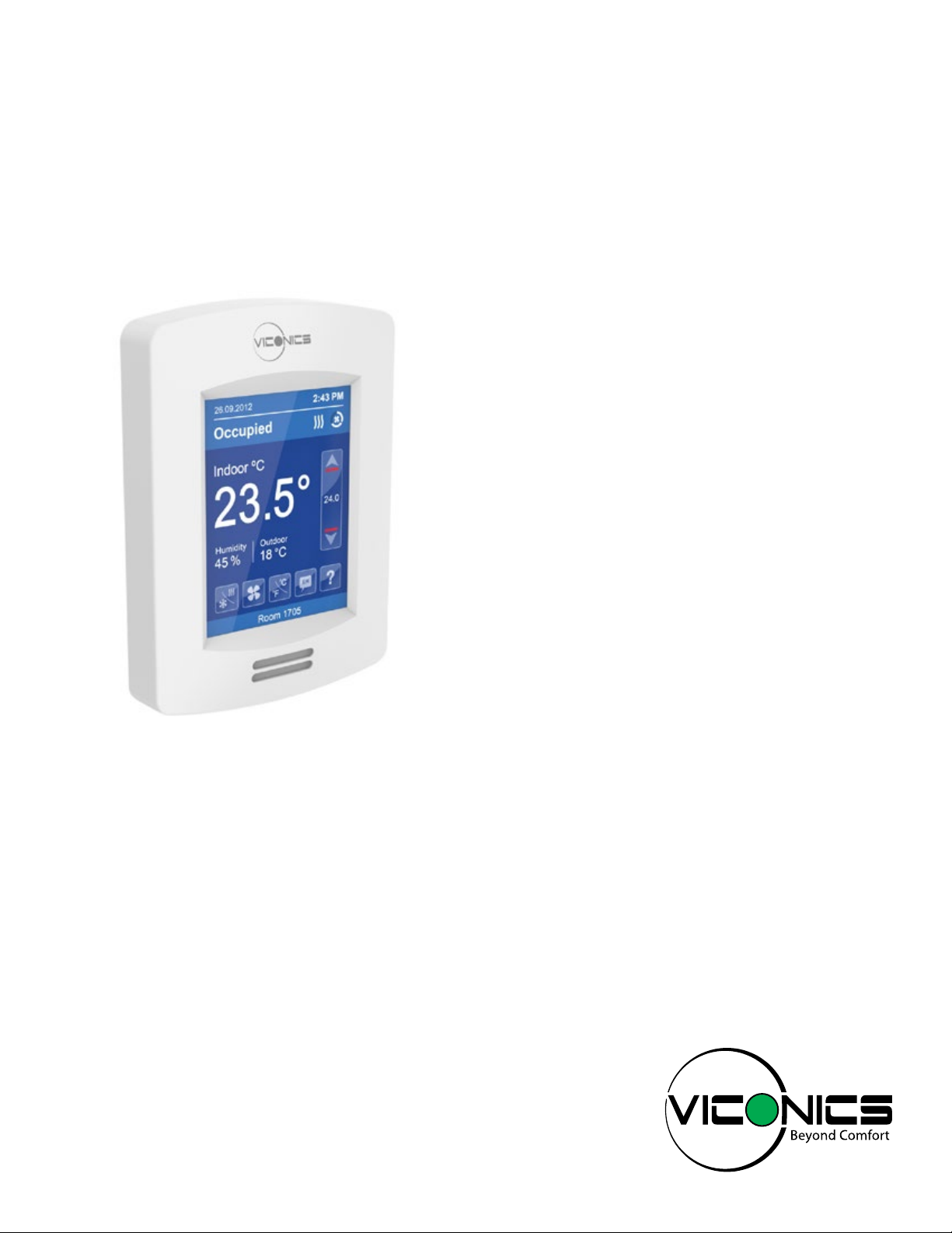
Preparation
• Remove the security screw (if any) on the bottom of the Terminal Equipment
Controller cover.
• Open unit by pulling on bottom side of the Terminal Equipment Controller
(Fig. 1).
• Read FCC ID and IC label installed in cover before installing any wireless
product.
• Ensure correct side of base faces up.
Location
1. Do not install on outside wall.
2. Do not install in areas with direct heat source.
3. Do no install near any air discharge grill.
4. Do not install in areas exposed to direct sunlight.
5. Ensure Controller has sufficient air circulation.
6. Ensure wall surface is flat and clean.
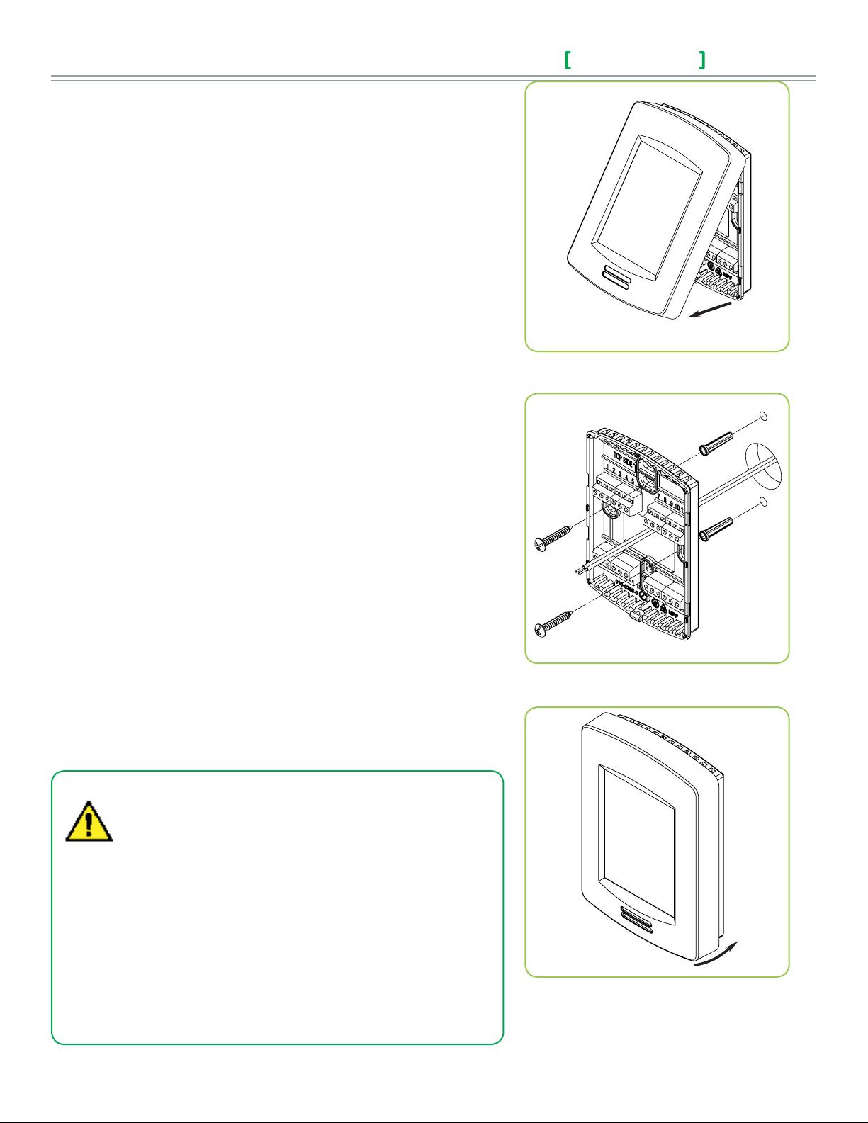
Installation
1. Pull cables 15 cm ( 6” ) out from wall.
2. Align base and mark location of two mounting holes on wall.
3. Install anchors in wall.
4. Insert cable in central hole of base.
5. Insert screws in mounting holes on each side of base.
6. Strip each wire 1/4” ( 0.6 cm) from end.
7. Insert each wire and screw according to wiring chart.
8. Gently push excess wiring back into hole.
9. Gently align cover to top of base and snap in place from bottom.
10. Install security screw.
Installation Guide
Figure-1 Ope n the cover
Figure-2 Install the bas e
VT8300 Series
• If replacing an existing Line Voltage FCU Controller, label wires
before removal of Controller.
• Electronic controls are static sensitive devices. Discharge
yourself correctly before manipulating and installing Controller.
• A short circuit or wrong wiring may permanently damage
Controller or equipment.
• All VT8300 ® series controls are designed for use as operating
controls only and are not safety devices. Tampering with the
devices or unintended application of the devices will result in a
void of warranty.
• This device must be installed to provide a separation distance
of at least 8in (40cm) from all persons and must not be
collocated or operating in conjunction with any other antenna
Figure-3 Reinstall cover
or transmitter.
Viconics Technologies Inc. | 9245 La ngeli er Blvd. | St.-Leonard | Quebec | Canada | H1P 3K9 | Tel : (514) 321-5660 | Fa x: ( 514) 32 1-415 0
028-0429-02 www.viconics.com | sales @viconics.com February 2015
©2015 Viconics Technologies Inc. All rights reserved.
Page 3

Installation Guide
VT8300 Series
3
CONFIGURABLE BI/UI UNIVERSAL INPUTS OVERVIEW
Universal input #16 can be configured for the following binary
functions:
1. (None): No function will be associated with the input
2. (Rem NSB): remote NSB timer clock input. The scheduling will now be
set as per the binary input. It provides low cost setback operation via a dry
contact.
Contact opened = Occupied
Contact closed = Unoccupied
3. (Motion NO) and (Motion NC): Advanced PIR occupancy functions using
a normally open (NO) or normally closed (NC) remote PIR motion sensor.
Occupancy mode is now set as per applied PIR function and configuration.
Application information and examples are available on document: APP-PIRSE8xxx. This document will provide the installers and system designers with
detailed examples on applications, parameter configuration information,
sequence of operation, troubleshooting and diagnostic help required for the
proper usage of the onboard PIR sensor.
4. (Window) EMS: Forces the system to disable any current heating or cooling
action by the Terminal Equipment Controller. The mode stays the same and
the current setpoints are the same occupied setpoints. Only the outputs
are disabled. There is a Door/Window alarm displayed on the Terminal
Equipment Controller to indicate to the local tenant that the door/window
needs to be closed for cooling or heating to resume. Use NC contact.
Contact opened = System disabled with local Window alarm
Contact closed = System enabled
Universal input #17 can be configured for the following binary
functions:
1. (None): No function will be associated with the input
2. (Door Dry) Door contact & Motion detector: This configuration is only
functional if binary input #1 is set to Motion NO or Motion NC or an onboard
PIR sensor is used. With this sequence enabled, the occupancy is now
dictated through those 2 inputs. Any motion detected will set the zone
to occupied status. The zone will remain permanently in occupied mode
until the door contact switch opens momentarily. The Terminal Equipment
Controller will then go in stand-by mode. If more movements are detected,
the occupied mode will resume. While the door is opened, any movements
detected by the remote PIR sensor or the onboard PIR sensor will be
ignored. Use a Normally Closed contact switching device.
4. (Filter): a Filter alarm short text message will be
displayed on the Terminal Equipment Controller
screen when the input is energized. It can be
tied to a differential pressure switch that monitor
filters
Contact opened = No alarm
Contact closed = Alarm displayed
5. (Service): a Service alarm short text message
will be displayed on the Terminal Equipment
Controller screen when the input is energized. It
can be tied in to the AC unit control card, which
provides an alarm in case of malfunction.
Contact opened = No alarm
Contact closed = Alarm displayed
Universal input #19 can be configured for
the following functions:
1. (None): No function will be associated with the
input
2. (COC/NH) Change over dry contact.
Normally Heat: Used for hot / cold air / water
change over switching in 2 pipe systems.
Contact closed = Cold air/water present
Contact opened = Hot air/water present
Only used and valid if Room Controller is set
up for a 2 pipe system.
3. (COC/NC) Change over dry contact.
Normally Cool: Used for hot / cold air / water
change over switching in 2 pipe systems.
Contact closed = Hot air/water present
Contact opened = Cold air/water
present
Only used and valid if Room Controller is set
up for a 2 pipe system.
4. (COS) Change over analog sensor: Used for
hot / cold air / water change over switching in 2
pipe systems.
Contact opened = Door opened
Contact closed = Door closed
3. (RemOVR): temporary occupancy remote override contact. This function
disables the central button override function on the Terminal Equipment
Controller. The override function is now controlled by a manual remote
momentarily closed contact. When configured in this mode, the input
operates in a toggle mode. It is now possible to toggle between unoccupied
& occupied setpoints for the amount of time set by parameter (TOccTime)
temporary occupancy time.
Viconics Technologies Inc. | 9245 La ngeli er Blvd. | St.-Leonard | Quebec | Canada | H1P 3K9 | Tel : (514) 321-5660 | Fa x: ( 514) 32 1-415 0
028-0429-02 www.viconics.com | sales @viconics.com February 2015
Only used and valid if Room Controller is set
up for a 2 pipe system.
If temperature is > 77 °F = Hot air / water
present
If temperature is < 75 °F = Cold air / water
present
©2015 Viconics Technologies Inc. All rights reserved.
Page 4

4
TERMINAL IDENTIFICATION & FUNCTION
Terminal identification
Installation Guide
VT8300 Series
VT83xxU
Description / Application
2 & 4 Pipe 2 & 4 Pipe 2 & 4 Pipe
Control Type = On/Off Control Type = Floating Control Type = Analog
Internal Temperature X X X
Internal Humidity
1- BO1
2- BO2
3- BO3
4- BO4
5- RC / 24 V~ Hot
6- C / 24 V~ Com
7- RH
8- BO8
9- UO9
10- UO10
11- UO 11
12- UO12
Model Dependent Model Dependent Model Dependent
Not used Not used Not used
Fan-L Fan-L Fan-L
Fan-M Fan-M Fan-M
Fan-H Fan-H Fan-H
24 V~ Hot 24 V~ Hot 24 V~ Hot
24 V~ Com 24 V~ Com 24 V~ Com
Aux Heat Aux Heat Aux Heat
Aux Heat Aux Heat Aux Heat
Normally Close Cool Valve Close Cool Valve Not used
Normally Close Heat Valve Close Heat Valve Not used
Normally Open Cool Valve Open Cool Valve Analog Heat valve
Normally Open Heat Valve Open Heat Valve Analog Cool Valve
Used in applications
13- RS485 +
14- RS485 -
15- RS485 Ref
16- UI16
17- UI17
18- Common
19- UI19
20- UI20
21- Common
22- UI22
23- UI23
24- UI24
BACnet MS-TP + BACnet MS-TP + BACnet MS-TP +
BACnet MS-TP - BACnet MS-TP - BACnet MS-TP -
BACnet MS-TP Ref BACnet MS-TP Ref BACnet MS-TP Ref
UI16 Function UI16 Function UI16 Function
UI17 Function UI17 Function UI17 Function
Common Common Common
UI19 Function UI19 Function UI19 Function
Remote Room Sensor Remote Room Sensor Remote Room Sensor
Common Common Common
Remote Supply Sensor Remote Supply Sensor Remote Supply Sensor
Not used Not used Not used
Not used Not used Not used
Viconics Technologies Inc. | 9245 La ngeli er Blvd. | St.-Leonard | Quebec | Canada | H1P 3K9 | Tel : (514) 321-5660 | Fa x: ( 514) 32 1-415 0
028-0429-02 www.viconics.com | sales @viconics.com February 2015
©2015 Viconics Technologies Inc. All rights reserved.
Page 5

Installation Guide
2 Pipe Applications
Com
24Vac
Com
4 Pipe Applications
2 Pipe Applications 4 Pipe Applications
Com
24Vac
Com
24Vac
Com
Open
Close
Com
Open
Com
24Vac
Com
24Vac
Com
Open
Close
Com
24 Vac
0-10 Vdc
Com
Com
24Vac
Com
24Vac
Com
Open
Close
Com
Open
Close
Com
24Vac
Com
24Vac
Com
Open
Close
Com
Open
Close
VT8300 Series
Wiring
Power & Fan (All Models)
3 Speed 2 Speed Single Speed
LOW LOW
LOW LOW
MED
MED
5
HIGH HIGH
HIGHHIGH HIGH
HIGH
BO8 Auxilliary output wiring
Dry contact to end device 24 V~ maximum 24 Vac power to relay
RC (24 Vac)
C (Common)
RC (24 Vac)
C (Common)
R
RH
BO8 - Aux Heat
Main outputs wiring
2 Pipe Applications 4 Pipe Applications
Control type = On-Off
RH
BO8 - Aux Heat
24 Vac
Transformer
R
UO9
UO11
OR
Heating / Cooling valve
Com
24Vac
Floating control
UO11
UO9
Heating / Cooling valve
Com
Open
Close
Analog control
UO10 NC
UO12 NO
UO11 NO
UO11 NC
UO12
UO10
UO11
UO9
Com
OR
OR
24Vac
Com
24Vac
Com
Open
Close
Com
Open
Close
Heating valve
Cooling valve
Heating valve
Cooling valve
Heating / Cooling valve
Com
24Vac
UO12
Viconics Technologies Inc. | 9245 La ngeli er Blvd. | St.-Leonard | Quebec | Canada | H1P 3K9 | Tel : (514) 321-5660 | Fa x: ( 514) 32 1-415 0
028-0429-02 www.viconics.com | sales @viconics.com February 2015
0-10Vdc
UO11
UO12
Com
24 Vac
0-10 Vdc
Com
24 Vac
0-10 Vdc
Heating valve
Cooling valve
©2015 Viconics Technologies Inc. All rights reserved.
Page 6

6
24 Vac fan relays
TYPICAL APPLICATIONS
Schematic Wiring Settings
Normally Closed
3 Speed Fan
Sensor
Room Temperature
Control Thermostat
On/Off
Cooling / Heating
Valve
2 pipe system cooling and/or heating
Control type = On / Off
24 Vac fan relays
2
3
4
5
6
7
8
9
10
11
12
18
19
BO2 - Fan L
BO3 - Fan M
BO4 - Fan H
RC (24 Vac)
C (Common)
RH
BO8 - Aux Heat
UO9 NC
UO10
UO11
UO12
SCom
UI 19 - UI13
LOW
MED
HIGH
Optional supply water
temperature sensor
24 Vac Transformer
Normally Closed
2 pipe system cooling and/or heating
Control type = Floating
Installation Guide
VT8300 Series
Mandatory
• Pipe no = 2 pipes
• CntrltTyp = On/Off
• Fan Menu = 0 (L-M-H)
• FL time = N/A
If cooling only set::
• SeqOpera = 0 Cooling only
If heating only set:
• SeqOpera = 1 Heating only
If heat / cool auto-changeover with
a local water temperature sensor set:
• SeqOpera = 0 Cooling only
• UI3 = COS
3 Speed Fan
Room Temperature
Control Thermostat
Modulating Floating
Cooling / Heating
Sensor
Valve
2
3
4
5
6
7
8
9
10
11
12
18
19
BO2 - Fan L
BO3 - Fan M
BO4 - Fan H
RC (24 Vac)
C (Common)
RH
BO8 - Aux Heat
UO9
UO10
UO11
UO12
SCom
UI 19 - UI13
LOW
MED
HIGH
Optional supply water
temperature sensor
24 Vac Transformer
Normally Closed
Mandatory
• Pipe no = 2 pipes
• CntrltTyp = Floating
• Fan Menu = 0 (L-M-H)
• FL time = as per actuator
If cooling only set:
• SeqOpera = 0 Cooling only
If heating only set:
• SeqOpera = 1 Heating only
If heat / cool auto-changeover with
a local water temperature sensor set:
• SeqOpera = 0 Cooling only
• UI3 = COS
Viconics Technologies Inc. | 9245 La ngeli er Blvd. | St.-Leonard | Quebec | Canada | H1P 3K9 | Tel : (514) 321-5660 | Fa x: ( 514) 32 1-415 0
028-0429-02 www.viconics.com | sales @viconics.com February 2015
©2015 Viconics Technologies Inc. All rights reserved.
Page 7

Installation Guide
24 Vac fan relays
Schematic Wiring Settings
3 Speed Fan
Sensor
Room Temperature
Control Thermostat
VT8300 Series
Modulating Analog
Cooling / Heating
Valve
2 pipe system cooling and/or heating
Control type = Analog
24 Vac fan relays
2
3
4
5
6
7
8
9
10
11
12
18
19
BO2 - Fan L
BO3 - Fan M
BO4 - Fan H
RC (24 Vac)
C (Common)
RH
BO8 - Aux Heat
UO9
UO10
UO11
UO12
SCom
UI 19 - UI13
LOW
MED
HIGH
Optional supply water
temperature sensor
24 Vac Transformer
0 to 10
Vdc
Normally Closed
7
Mandatory
• Pipe no = 2 pipes
• CntrltTyp = Analog
• Fan Menu = 0 (L-M-H)
• RA/DA = as per actuator
If cooling only set:
• SeqOpera = 0 Cooling only
If heating only set:
• SeqOpera = 1 Heating only
If heat / cool auto-changeover with
a local water temperature sensor set:
• SeqOpera = 0 Cooling only
• UI3 = COS
4 pipe system cooling and heating
Control type = On / Off
3 Speed Fan
Room Temperature
Control Thermostat
Normally Closed
On/Off
Cooling
Valve
Heating
Valve
2
3
4
5
6
7
8
9
10
11
12
BO2 - Fan L
BO3 - Fan M
BO4 - Fan H
RC (24 Vac)
C (Common)
RH
BO8 - Aux Heat
UO9 NC
UO10
UO11 NC
UO12
LOW
MED
HIGH
Normally Closed
Heating
24 Vac Transformer
Cooling
Mandatory
• Pipe no = 4 pipes
• CntrltTyp = On/Off
• Fan Menu = 0 (L-M-H)
• SeqOpera = 4 Cool/Heat
4 pipe system cooling and heating
Control type = Floating
24 Vac fan relays
LOW
MED
HIGH
Heating
24 Vac Transformer
Cooling
Mandatory
• Pipe no = 4 pipes
• CntrltTyp = Floating
• Fan Menu = 0 (L-M-H)
• FL time = as per actuator
• SeqOpera = 4 Cool/Heat
3 Speed Fan
Room Temperature
Modulating Floating
Cooling
Valve
Heating
Valve
2
3
4
5
6
7
8
9
10
11
12
BO2 - Fan L
BO3 - Fan M
BO4 - Fan H
RC (24 Vac)
C (Common)
RH
BO8 - Aux Heat
UO9
UO10
UO11
UO12
Control Thermostat
Viconics Technologies Inc. | 9245 La ngeli er Blvd. | St.-Leonard | Quebec | Canada | H1P 3K9 | Tel : (514) 321-5660 | Fa x: ( 514) 32 1-415 0
028-0429-02 www.viconics.com | sales @viconics.com February 2015
©2015 Viconics Technologies Inc. All rights reserved.
Page 8

8
3 Speed Fan
Installation Guide
Schematic Wiring Settings
4 pipe system cooling and heating
Control type = Analog
Modulating Analog
Cooling
Valve
Room Temperature
Control Thermostat
Heating
Valve
2
3
4
5
6
7
8
9
10
11
12
BO2 - Fan L
BO3 - Fan M
BO4 - Fan H
RC (24 Vac)
C (Common)
RH
BO8 - Aux Heat
UO9
UO10
UO11
UO12
2 pipe system cooling or heating with reheat
Control type = Floating
24 Vac fan relays
LOW
MED
HIGH
0 to 10
Vdc
Heating
24 Vac Transformer
0 to 10
Vdc
Cooling
Mandatory
• Pipe no = 4 pipes
• CntrltTyp = Analog
• Fan Menu = 0 (L-M-H)
• RA/DA = as per actuator
• SeqOpera = 4 Cool/Heat
VT8300 Series
3 Speed Fan
Modulating Floationg
Cooling / Heating
Valve
Sensor
Room Temperature
Control Thermostat
Electric
Reheat
2
3
4
5
6
7
8
9
10
11
12
18
19
BO2 - Fan L
BO3 - Fan M
BO4 - Fan H
RC (24 Vac)
C (Common)
RH
BO8 - Aux Heat
UO9
UO10
UO11
UO12
SCom
UI 19 - UI13
24 Vac fan relays
LOW
MED
HIGH
Electric
Reheat
Optional supply water
temperature sensor
24 Vac Transformer
Normally Closed
Mandatory
• Pipe no = 2 pipes
• CntrltTyp = Floating
• Fan Menu = 0 (L-M-H)
• FL time = as per actuator
• SeqOpera = 2 Cool/Reheat
• UI3 = COS
Viconics Technologies Inc. | 9245 La ngeli er Blvd. | St.-Leonard | Quebec | Canada | H1P 3K9 | Tel : (514) 321-5660 | Fa x: ( 514) 32 1-415 0
028-0429-02 www.viconics.com | sales @viconics.com February 2015
©2015 Viconics Technologies Inc. All rights reserved.
Page 9

Installation Guide
VT8300 Series
REMOTE SENSOR ACCESSORIES
Model no. Description
S3010W1000 Wall mounted temperature sensor
S3020W1000 Wall mounted temperature sensor with override button and occupancy status
LED
The VT8300 room controller is compatible with remote mount temperature sensors using 10K type 2 NTC thermistors.
Note:
If one or multiple sensor(s) is/are connected into the RS terminal, the internal temperature sensor is automatically disabled. Disconnecting
the sensor(s) in the RS terminal will re-activate the internal sensor.
Features:
• Each sensor can be configured for various averaging combinations
• Optional occupancy led
• Optional override key
Wiring example of single remote room sensor:
9
VT8300
Series Controller
Common
UI 20
BO8
24 Vac Com
UI17
S3020W1000
Remote wiring 1 sensor
S2-1= On, S2-2=On
SCom
OR
RS
Aux
C
DI
S3010W1000
Remote wiring 1 sensor
S2-1= On, S2-2=On
SCom
RS
Dip switch
setting for:
1 sensor
ON
1 2
S2-1 = ON
S2-2 = ON
Viconics Technologies Inc. | 9245 La ngeli er Blvd. | St.-Leonard | Quebec | Canada | H1P 3K9 | Tel : (514) 321-5660 | Fa x: ( 514) 32 1-415 0
028-0429-02 www.viconics.com | sales @viconics.com February 2015
©2015 Viconics Technologies Inc. All rights reserved.
Page 10

10
VT8300
2 x S3010W1000
1 2
1 2
Installation Guide
Wiring examples of 2 remote room sensors for averaging applications:
VT8300 Series
VT8300
Series Controller
Common
UI 20
BO8
24 Vac Com
UI17
Series Controller
Common
UI 20
1 x S3010W1000 & 1 x S3020W1000
Remote wiring 2 sensor
S2-1= On, S2-2=Off
SCom
RS
Aux
C
DI
Remote wiring 2 sensor
S2-1= On, S2-2=Off
SCom
RS
SCom
RS
SCom
RS
Notes for averaging applications:
• S3010W1000andS3020W1000canbe
mixedmatched.
• S3010W1000andS3020W1000aretobe
wiredinparallel.
• Respectthedipswitchsettingineach
remotesensor.
VT8300
Series Controller
Common
UI 20
BO8
24 Vac Com
UI17
Dip switch
setting for:
2 sensors
2 x S3020W1000
Remote wiring 2 sensor
S2-1= On, S2-2=Off
SCom
RS
Aux
C
DI
ON
S2-1 = ON
S2-2 = OFF
SCom
RS
Wiring examples of 3 remote room sensors for averaging applications:
VT8300
Series Controller
Common
UI 20
BO8
24 Vac Com
UI17
Temperature vs. resistance chart for 10 Kohm NTC thermistor (R25°C = 10KΩ±3%, B25/85°C = 3975K±1.5%)
ºC ºF Kohm ºC ºF Kohm ºC ºF Kohm ºC ºF Kohm ºC ºF Kohm
-40 -40 324.3197 -20 -4 94.5149 0 32 32.1910 20 68 12.4601 40 104 5.3467
-35 -31 234.4009 -15 5 71.2430 5 41 25.1119 25 77 10.0000 45 113 4.3881
-30 -22 171.3474 -10 14 54.1988 10 50 19.7390 30 86 8.0694 50 122 3.6202
-25 -13 126.6109 -5 23 41.5956 15 59 15.6286 35 95 6.5499 55 131 3.0016
2 x S3010W1000 & 1x S3020W1000
Remote wiring 3 sensor
S2-1= Off, S2-2=Off
SCom
RS
Aux
C
DI
SCom
RS
SCom
RS
VT8300
Series Controller
Common
UI 20
3 x S3010W1000
Remote wiring 3 sensor
S2-1= Off, S2-2=Off
SCom
RS
Dip switch
setting for:
3 sensors
SCom
RS
ON
S2-1 = OFF
S2-2 = OFF
SCom
RS
028-0429-02 www.viconics.com | sales @viconics.com February 2015
Viconics Technologies Inc. | 9245 La ngeli er Blvd. | St.-Leonard | Quebec | Canada | H1P 3K9 | Tel : (514) 321-5660 | Fa x: ( 514) 32 1-415 0
©2015 Viconics Technologies Inc. All rights reserved.
Page 11

Installation Guide
VT8300 Series
HOME SCREEN DISPLAY
11
Hospitality User Interface Shown
Date
Occupancy Status
Indoor Temperature
Indoor Humidity
Outdoor Temperature
System Mode
Short Network
Message
Time
System Status
Fan Status
Up Arrow
Increase Temperature Setpoint
Actual Setpoint
Down Arrow
Decrease Temperature
Setpoint
Help
Fan Mode
Language Selection
Temperature Units
Note: User HMI is configurable and allows display functions such as Date, Time,
Humidity, Outdoor Temperature, Setpoint, and others to be enabled or disabled by
setting various parameters.
Viconics Technologies Inc. | 9245 La ngeli er Blvd. | St.-Leonard | Quebec | Canada | H1P 3K9 | Tel : (514) 321-5660 | Fa x: ( 514) 32 1-415 0
028-0429-02 www.viconics.com | sales @viconics.com February 2015
©2015 Viconics Technologies Inc. All rights reserved.
Page 12

12
Setup
Network
Configuration
Setpoints - Display
Service view
Test outputs
HOW TO ENTER SET-UP SCREEN
Installation Guide
VT8300 Series
SET-UP SCREEN DISPLAY
Touch and hold this point
for 3 seconds to enter set-up mode
Note: If a configuration/installer
password is activated to prevent
unauthorised access to the
configuration menu parameters, a
password entry prompt shows to
prevent access to device configuration
components.
For more information on using and
configuring the functions of the HMI,
refer to the following document:
VT8300 Series
Terminal Equipment Controller
User Interface Guide
Return to
home screen
Enter BACnet
Enter parameter configuration menu
Enter setpoint & display settings
Enter status and service view
Enter output testing mode
Enter language selection
Discover Mode The Controller
becomes discoverable on the wireless
ZigBee® network for 1 minute (this
button is hidden if ZigBee® settings are
not configured)
®
& ZigBee® network settings
General Note:
Adjustable parameter
Non-adjustable parameter
Viconics Technologies Inc. | 9245 La ngeli er Blvd. | St.-Leonard | Quebec | Canada | H1P 3K9 | Tel : (514) 321-5660 | Fa x: ( 514) 32 1-415 0
028-0429-02 www.viconics.com | sales @viconics.com February 2015
©2015 Viconics Technologies Inc. All rights reserved.
Page 13

Installation Guide
VT8300 Series
APPENDIX A: TERMINAL CORRESPONDANCE
The terminals of a VT8300 are identified differently and have a wider range of possible functions compared to those of any of the
VT7000 series Room Controllers. Nonetheless, there is a direct correspondance of functions between the terminals of the VT7000
series and the VT8300 series. Consult the table below to verify the appropriate terminal when replacing a VT7000 Room
Controller with a VT8300 Room Controller.
VT7000 VT8300
Terminal name Terminal ID Terminal name Terminal ID
Binary Input 1 BI1 Universal Input 16 UI16
Binary Input 2 BI2 Universal Input 17 UI17
Universal Input 3 UI3 Universal Input 19 UI19
Sensor Common Scom Terminal 18 Common COM
Remote Sensor RS Universal Input 20 UI20 - RS
Sensor Common Scom Terminal 21 Common COM
Mix/Supply Sensor MS Universal Input 22 UI22 - SS
13
APPENDIX B: POWER OUTAGE CLOCK RESET
In the event of a power outage, VT8300 Room Controllers retain the correct time as long as the duration of the power outage is
not prolonged. Depending on the duration of the power outage, the Room Controllers internal clock may need to be updated
or reset completely. The following table gives an indication of the expected clock performance after a power outage of a given
duration.
Outage duration Room Controller behaviour
0 - 24 hours Clock functions are normal
24 - 36 hours Clock accuracy not guaranteed, time may need to be adjusted
36 - 72 hours Clock no longer increments and will need to be adjusted when power is
restored.
72+ hours Clock functions are fully reset, and will need to be reinitialized as per a
new installation.
Viconics Technologies Inc. | 9245 La ngeli er Blvd. | St.-Leonard | Quebec | Canada | H1P 3K9 | Tel : (514) 321-5660 | Fa x: ( 514) 32 1-415 0
028-0429-02 www.viconics.com | sales @viconics.com February 2015
©2015 Viconics Technologies Inc. All rights reserved.
 Loading...