

Page 1
Device Replacement Procedure
VT8000 Series Room Controllers
Page 2

2
VT8000 Controller Replacement Guide
Overview
This procedure shows how to replace VT8000 Series Room Controllers which are already installed and set-up to communicate with a
front end Multi-purpose Manager (MPM) via Zigbee or BACnet.
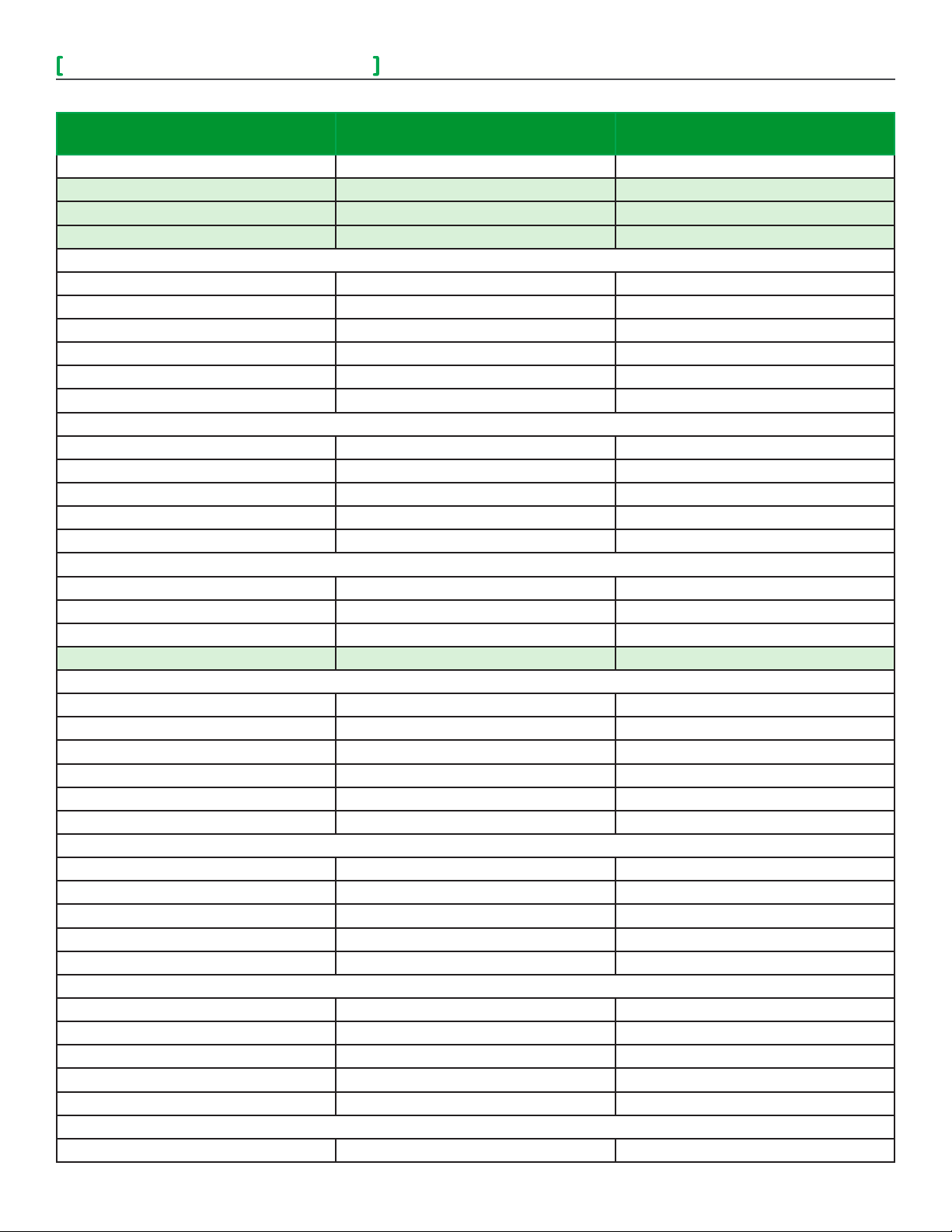
Use the following table to compare default values with the current parameter configurations on the VT8300/VT8350 before replacing the
Room Controller. Navigate through the Network, Configuration, and Setpoints/Display pages in the Setup menu and note the current
configurations if they are different from the default ones. Also, verify you are replacing the Room Controller with the same model.
• When replacing an installed Room Controller, turn off the HVAC
system to prevent any damage by potentially incorrect default
settings on the new Room Controller.
• Electronic controls are static sensitive devices. Discharge
yourself correctly before handling and installing Room Controller.
• Use high caution when installing Room Controller as a short
circuit or incorrect wiring may cause permanent damage to
Room Controller or equipment.
• All VT8000® series Room Controllers controls are designed
for use as operating controls only and are not safety devices.
Tampering with the Device or unintended application of the
Device will result in a void of warranty.
Legend
All models
VT8350 only
Note: ZigBee settings only apply if a ZIgBee
module is installed in Room Controller.
Object Name Default Configurations
1/2 Zigbee Network
COM Address 254
PAN ID 0
Channel 10
2/2 Zigbee others
Permit Join on
1/2 BACnet Network
COM Address 254
Network Units Imperial
Network Language English
BACnet Baud Rate Auto
1/7 Configuration
BI 1 / UI 16 Status None
BI 2 / UI 17 Status None
RUI 1 / UI 19 Status None
Occupancy Command Local occ.
2/7 Configuration
Auto Mode Enabled
Fan Menu (Sequence) On-Auto
Auto Fan Function AS
Standby Mode Abs
Standby Differential 2 °C ( 3 °F )
3/7 Configuration
Standby Time 0.5H
Unoccupied Time 0H
Viconics Technologies Inc. | 9245 Lan gelier Bl vd. | St.-Leonard | Quebec | Canada | H1P 3K9 | Tel: (514) 321-5660 | Fa x: (514 ) 3 21-415 0
028-0454-00 www.viconics.com | sales@viconics.com November 2014
Current Configurations
before Replacement
© 2014 Viconcis Technologies. All rights reserved.
Page 3
VT8000 Controller Replacement Guide
3
Object Name Default Configurations
Current Configurations
before Replacement
Temporary Occupancy Time 2H
Dehumidification Hysteresis 5%
Dehumidification Max Cooling 100%
Dehumidification Lockout Enabled
4/7 Configuration
CPH 4
Control Type Floating
BO8 Out Time 15 Minute
BO8 AuxOut Not Used
Floating Time 1.5 min
DA /RA DA
5/7 Configuration
Proportional Band 3°F (1.2°C)
Pipe Number 2
Sequence of Operation Heat only
Purge Sample Period 2 hours
Purge Open 2 Minutes
6/7 Configuration
Main Password 0
User Password 0
Calib. Temperature 0.0 °C
Calib. Humidity 0.0 %RH
1/2 Setpoints
Unoccupied Cool Setpoint 80°F (26.5°C)
Standby Cool Setpoint 78°F (26°C)
Occupied Cool Setpoint 75°F (24°C)
Occupied Heat Setpoint 72°F (22°C)
Standby Heat Setpoint 69°F (21°C)
Unoccupied Heat Setpoint 62°F (16.5°C)
2/2 Setpoints
Default Heating Setpoint 72°F (22°C)
Minimum Deadband 2°F (1°C)
Max. Heating limit 90°F (32°C)
Min. Cooling limit 54°F (12°C)
Dehumidify 50 %RH
1/2 Display
User HMI 0
Color White
Main Display Temperature
Use Standby Screen No
Long message background color White
2/2 Display
Display Language English
Viconics Technologies Inc. | 9245 Lan gelier Bl vd. | St.-Leonard | Quebec | Canada | H1P 3K9 | Tel: (514) 321-5660 | Fa x: (514 ) 3 21-415 0
028-0454-00 www.viconics.com | sales@viconics.com November 2014
© 2014 Viconcis Technologies. All rights reserved.
Page 4

4
VT8000 Controller Replacement Guide
Object Name Default Configurations
Current Configurations
before Replacement
Units (Temperature Scale) °C
Low Backlight 60%
Night Backlight 5%
RH display Enabled
The below parameters are not accessible through the Setup menu in the VT8300/VT8350. However, they can be modified via the front
end Room Controllers once the device is online.
Object Name Default Configurations Current Configurations before
Replacement
More BACnet/ZigBee objects
System Mode Sequence#1 (Heat only)
Fan Mode N/A
Short Screen Message (BACnet only) Off
Long Screen Message (BACnet only) Off
Display Long Screen Message No
Heating Demand Limit N/A
Cooling Demand Limit N/A
No Activity Sleep Mode Disabled
Depending on Firmware version of MPM, some properties (such as Display Long Screen Message) do not show up in the Objects list.
NOTE
This document has one procedure to remove a Room Controller on a ZigBee Network and one procedure to remove a Room Controller
on a BACnet Network. Make sure to use the correct procedure.
Viconics Technologies Inc. | 9245 Lan gelier Bl vd. | St.-Leonard | Quebec | Canada | H1P 3K9 | Tel: (514) 321-5660 | Fa x: (514 ) 3 21-415 0
028-0454-00 www.viconics.com | sales@viconics.com November 2014
© 2014 Viconcis Technologies. All rights reserved.
Page 5

VT8000 Controller Replacement Guide
ZigBee Network
1. Remove security screw on bottom of Room Controller cover.
2. Open unit by pulling on bottom side of Room Controller cover (Figure 1).
3. Remove cover.
5
Figure 1 Cover
4. Open new VT8300/VT8350 Room Controller box and separate back plate from front plate.
5. Remove ZigBee communication module on back of front plate and install on the back side of front plate of
new Room Controller (Figure 2).
Figure 2 Communication Module
Viconics Technologies Inc. | 9245 Lan gelier Bl vd. | St.-Leonard | Quebec | Canada | H1P 3K9 | Tel: (514) 321-5660 | Fa x: (514 ) 3 21-415 0
028-0454-00 www.viconics.com | sales@viconics.com November 2014
© 2014 Viconcis Technologies. All rights reserved.
Page 6

6
VT8000 Controller Replacement Guide
6. Mount the front plate on the existing back plate installed on the wall.
NOTE: Ensure small plastic projections at top of front plate align with notches at top of back plate.
Figure 3 Secure Unit
7. Push on front plate bottom two corners to secure unit in place (Figure 3).
8. Wait for Room Controller to power up.
9. Use the table on earlier pages to re-configure your parameters such as sequence of operation, pipe number, occupied
heating/cooling setpoints.
10. Make sure Channel, Pan ID, and Com address match previous settings before replacement to bring Room Controller
back online.
Note: In the event a new ZigBee module is being used instead of the pre-exsisting one, the Room Controller must
be bound to the MPM again.
Viconics Technologies Inc. | 9245 Lan gelier Bl vd. | St.-Leonard | Quebec | Canada | H1P 3K9 | Tel: (514) 321-5660 | Fa x: (514 ) 3 21-415 0
028-0454-00 www.viconics.com | sales@viconics.com November 2014
© 2014 Viconcis Technologies. All rights reserved.
Page 7

VT8000 Controller Replacement Guide
BACnet Network
1. Remove security screw on bottom of Room Controller cover.
2. Open unit by pulling on bottom side of Room Controller cover (Figure 1).
3. Remove cover.
7
Figure 1 Cover
4. Open new VT8300/VT8350 Room Controller box and separate back plate from front plate.
5. Mount new front plate on existing back plate installed on the wall.
NOTE: Ensure small plastic projections at top of front plate align with notches at top of back plate.
6. Push on front plate bottom two corners to secure unit in place (Figure 2).
Figure 2 Secure Unit
7. Wait for Room Controller to power up.
8. Use the table on earlier pages to re-configure your parameters such as sequence of operation, pipe number, occupied heating/
cooling setpoints.
9. Make sure Channel, Pan ID, and Com address match previous settings before replacement to bring Room Controller back online.
Viconics Technologies Inc. | 9245 Lan gelier Bl vd. | St.-Leonard | Quebec | Canada | H1P 3K9 | Tel: (514) 321-5660 | Fa x: (514 ) 3 21-415 0
028-0454-00 www.viconics.com | sales@viconics.com November 2014
© 2014 Viconcis Technologies. All rights reserved.
 Loading...