

Page 1

Viconics VT7682S
Wireless Central Manager
Application Guide
VT7682S_Application_Guide-E00
(028-6041 R0 Issue Date: January 10th, 2012)
Table of Contents
Product Overview ............................................................................................................................................ 1
1.1. Features & Benefits ......................................................................................................................... 1
1.2. System Overview & Architecture ..................................................................................................... 2
1.3. Models Available .............................................................................................................................. 2
1.4. Terminal Identification & Functions ................................................................................................. 3
1.5. Screw Terminal Arrangement .......................................................................................................... 3
Integration & Global Commands ..................................................................................................................... 4
1.6. Alarms .............................................................................................................................................. 4
1.7. Outdoor air temperature .................................................................................................................. 5
Typical Application ........................................................................................................................................... 5
1.8. Example of two different systems: ................................................................................................... 6
Wireless Communication Overview ................................................................................................................. 7
Basic Initial Design and Deployment Consideration ........................................................................................ 8
1.9. Knowing and understanding the 6A / 5H rule of Zigbee and how to cover orphan nodes .............. 8
1.10. 6A stands for a maximum 6 addresses per device / node / controller............................................. 8
1.11. Orphan Nodes. ................................................................................................................................ 9
1.12. 5H stands for 5 hops maximum recommended. ............................................................................ 10
1.13. Best practice Zigbee initial network start-up procedure ................................................................ 10
Status LED Indicators .................................................................................................................................... 14
Tips & Things You Need to Know .................................................................................................................. 14
1.14. Compatibility .................................................................................................................................. 14
1.15. Maximum Devices ......................................................................................................................... 14
Troubleshooting Guide .................................................................................................................................. 15
Specifications ................................................................................................................................................. 16
Page 2
1
Administer 60 controller units with one Wireless Central
Manager.
Flexible control of multiple units with one central scheduler.
Compatible with all current Viconics wireless Terminal
Equipment Controllers.
Insures flexibility without having to invest in new equipment.
Provides multi control functionality.
Wireless Central Manager can control more than one unit
simultaneously.
Intuitive menu-driven, back-lit LCD display simplifies
scheduling.
Easy to commission with user friendly LCD display.
Basic DDC system features built into Wireless Central
Manager.
Provides all the basic required features of a DDC system in one
small package.
Centralized 7 day scheduling (2 or 4 events).
Simplifies scheduling of multiple units.
Central remote outdoor sensing capability for added
flexibility.
Centralized system lock out of heating and cooling modes.
Centralized remote alarm monitoring.
Provides easy alarm monitoring of zones which are in alarm mode
from one central location.
Lockable keypads for tamper proofing. No need for Terminal
Equipment Controller guards.
Eliminates tampering or unauthorized modifications of unit settings.
Allows for setting of central occupied heating and cooling
setpoints.
Effortless adjustment of heating and cooling set points from one
central location.
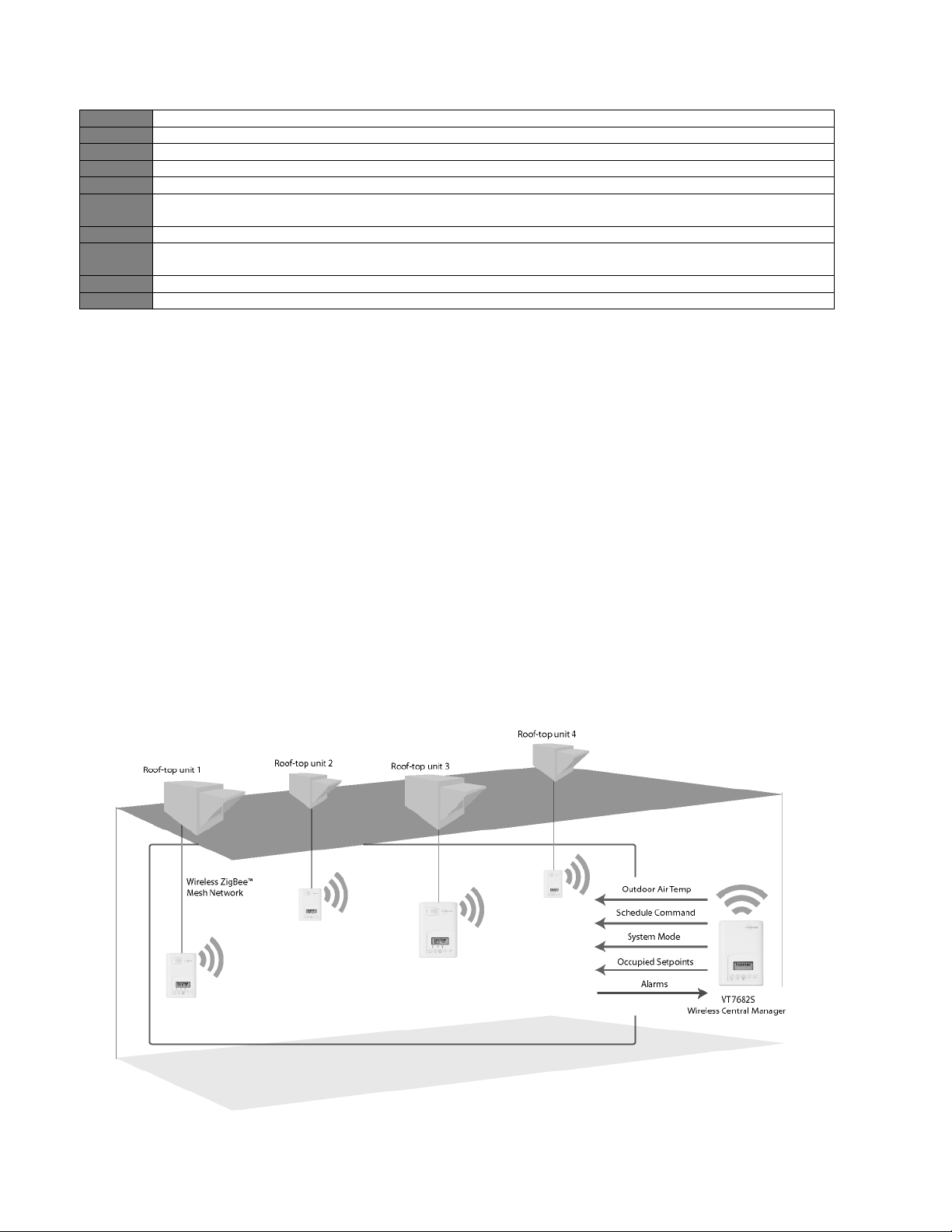
Product Overview
The Viconics VT7682S Wireless Central Manager allows for simple yet flexible management of multiple
equipment controllers from one convenient location. Facility managers can now efficiently administer
parameters for up to 60 room controllers with one Wireless Central Manager, saving both time and effort.
The Wireless Central Manager is compatible with all current Viconics wireless terminal equipment
controllers including fan-coil units, rooftop units and heat-pump models. The Wireless Central Manager
allows adjustment of set points, central system modes, global overrides, broadcasting of outdoor
temperature and central alarm reporting for installed equipment. The Wireless Central Manager will even
allow you to control more than one type of system simultaneously.
The Wireless Central Manager features an intuitive, menu-driven, back-lit LCD display, which guides users
through simple parameters such as setting central temperature set-points, timed events, system mode and
more.
The Wireless Central Manager Saves you time and money by providing a solution, which is simple to
install, yet does not skimp on functionality. The Wireless Central Manager provides most of the basic
required features of a DDC system at the cost of a typical standalone controller. The Wireless Central
Manager allows for night setback functionality across previously independent programmable and nonprogrammable standalone thermostats, which results in a more energy-efficient, unified building system.
Viconics has made it easier than ever to manage your building more effectively while saving energy with
the VT768S Wireless Central Manager!
1.1. Features & Benefits
Please check with your local government for instruction on disposal of this product.
Page 3
2
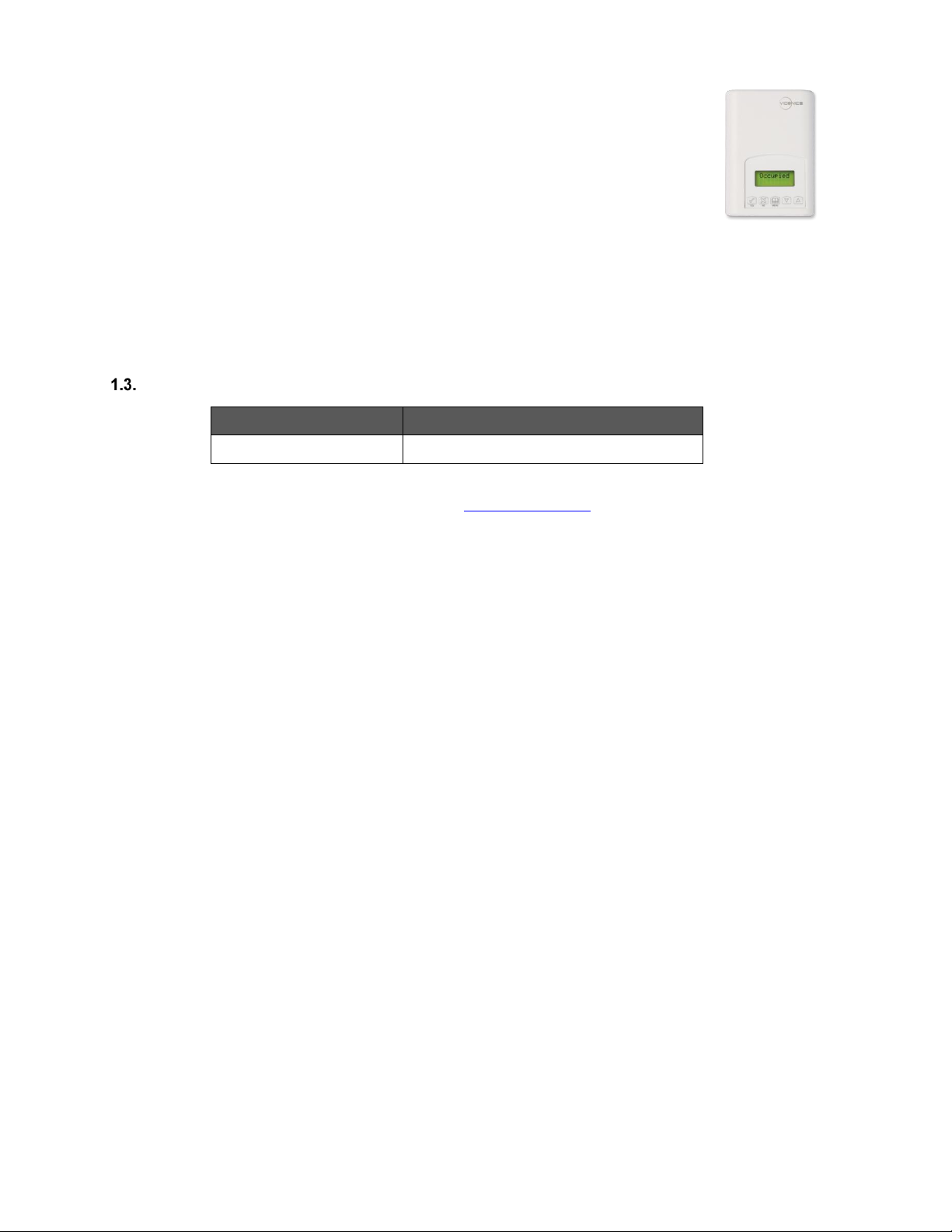
PART NUMBER
DESCRIPTION
VT7682S5000W
Wireless Central Manager
1.2. System Overview & Architecture
The Wireless Central Manager is also compatible with the new Viconics PIR cover accessories.
Devices equipped with a PIR cover provide advanced active occupancy logic, which will
automatically switch occupancy levels from Occupied to Unoccupied as required by local activity
being present or not. This advanced occupancy functionality provides advantageous energy savings
during occupied hours without sacrificing occupant comfort. All controllers can be ordered with or
without a factory installed PIR cover (see ordering notes below).
The following hardware is required for operation of the wireless manager, but not included:
24 VAC power supply. Typically taken directly from the RTU power supply (C & RC)
An outdoor air sensor (Optional)
Proper wiring of all components as per the installation manual
Proper network wires pulled through all devices communication connections
Models Available
The additional following documentation is available on www.viconics.com
- VT7682 installation guide available on document: LIT-VT7682S-Exx.
- Information on the Wireless models is available on documents: ITG-VWG-50-BAC-Exx and LIT-VWG-50-SETUP-Exx.
- Information on the survey tool available on document: MAN-VWG-SURVEY-Exx.
Page 4
3
Terminal Use
Terminal Identification
Description
4 – RC 24VAC hot
24 V ~ Hot
Power supply of controller (hot side)
5 – C 24VAC com
0 V ~ Com
Power supply of controller (com side)
14 – Scom
Scom
Reference input for OS
15 – OS
OS
Outside air temperature sensor input
Scom
OS
24 V ~ Hot
0 V ~ Com
Left top connector
Bottom connector
1.4. Terminal Identification & Functions
1.5. Screw Terminal Arrangement
Page 5
4
CLOCK
STATUS
SCHEDULE
STATUS
OUTDOOR TEMPERATURE
IF CONNECTED
ALARMS
Monday
12:00 AM
Occupied
Outdoor
x.x °C or°F
SetClock
Unoccupied
Zone X**
Override
Zone Y*
Zone Z**
Dup Zig
Duplicate Zigbee Address
Wireless Network (up to 60)
Wireless Central Manager
Wireless Controllers
(All Wireless Models)
Central Outdoor Temperature
Outdoor Temperature
Schedule
Occupancy Command
Setpoints
Occupied Heating Setpoint
Unoccupied Heating Setpoint
Occupied Cooling Setpoint
Unoccupied Cooling Setpoint
Central system mode
System Mode
Global commands all devices
(All Controllers)
Global commands specific devices
(Specific Controllers)
Central Global override
Temporary Occupancy Time
Central Alarm
See table below
Integration & Global Commands
The following figure shows which objects from the controller can be monitored and commanded from the
BAS front-end.
Manager Level Device Level
Figure 1: Global commands from a BAS front-end to a VT7600 series controller
1.6. Alarms
Sequence of auto-scroll status display of Wireless Central Manager
** X, Y, Z is the MAC address of the zone that has the alarm.
*** Restart the network by changing the PAN ID (See troubleshooting guide at the end of this document).
Page 6
5
Frost ON
Indicates that the heating is energized by the low limit frost protection room temperature setpoint 5.6 °C (42 °F).
SetClock
Indicates that the clock needs to be reset. There has been a power failure which has lasted longer than 6 hours.
Service
Indicates that there is a service alarm as per one of the configurable digital input.
Filter
Indicates that the filters are dirty as per one of the configurable digital input.
Fan lock
Indicates that the heating and cooling action are locked out due to a defective fan operation.
Window
Indicates that the outside window or door is opened and that the terminal equipment controller has cancelled any
cooling or heating action.
Discharg
Indicates that the discharge temperature is beyond maximum permissible value.
Low Batt
Indicates that one of the attached wireless switching devices (door or window contact) have a low battery
condition.
FreshAir
Indicates that the fresh air measurement is not within range.
CO2
Indicates that the CO2 level is beyond the maximum permissible value.
The Wireless Central Manager displays the zone MAC address of the device which contains the alarm. The
following are alarms which can be displayed by the controllers:
If alarms are detected, they will automatically be displayed at the end of the status display scroll.
During an alarm message display, the back lit screen will light up at the same time as the message and shut off during
the rest of the status display.
Two alarms maximum can appear at any given time.
The priority for the alarms is as follows:
First zone in, second zone in…subsequent zones in alarm will only display when the first one(s) are out.
The range of zones that can be in alarm is 1 to 253.
1.7. Outdoor air temperature
Outdoor air temperature display is only enabled when outdoor air temperature sensor is connected.
A maximum range status display of 50 °C (122 °F) indicates a shorted sensor. Associated functions, such as mode
lockouts and economizer function are automatically disabled.
A minimum range status -40 °C (-40 °F) is not displayed and indicates an opened sensor or a sensor not connected.
Associated functions, such as mode lockouts and economizer function are automatically disabled.
Typical Application
Page 7

6
1.8. Example of two different systems:
Cluster of controllers with same PAN ID and Channel from each system reporting to corresponding Wireless Central
Manager with same PAN ID and Channel.
Page 8

7
Wireless Communication Overview
The Viconics Wireless Central Manager and other related wireless controller family (VT7xxxXxxxxW) networkable
devices operate using ZigBee/IEEE 802.15.4 physical layer for communication.
General characteristics of the wireless physical communication layer are:
· Wireless physical layer of 2.4GHz with a data rates of 250 kbps
· Yields high throughput and low latency
· Automatic multiple topologies configuration: star, peer-to-peer, mesh
· Fully handshake protocol for transfer reliability
· Range: 30 feet / 10M typical (up to 100 feet / 30 M based on environment)
IEEE 802.15.4 along with ZigBee’s Network and Application Support Layer provide:
· Low cost installation deployment
· Ease of implementation
· Reliable data transfer
· Short range operation
· Very low power consumption
· Appropriate levels of security
Many network specific features of the IEEE 802.15.4 standard are not covered in detail in this paper. However, these
are necessary for the efficient operation of a ZigBee network. The features of the network physical layer include
receiver energy detection, link quality indication and clear channel assessment. Both contention-based and contentionfree channel access methods are supported with a maximum packet size of 128 bytes, which includes a variable
payload up to 104 bytes. Also employed are 64-bit IEEE and 16-bit short addressing, supporting over 65,000 nodes per
network. All the properties of the physical layer are used and employed by the Viconics mesh network but are hidden to
the user for ease of configuration and commissioning of the network database.
Page 9

8
Basic Initial Design and Deployment Consideration
IMPORTANT: It is HIGHLY recommended that you do a proper field survey with the Viconics survey tools to establish
connectivity limitations and architecture layout on ALL job sites considered for deployment with the Viconics wireless
controller products. Please refer to the following manual for the survey procedures and tool usage: MAN VWGSURVEY-Exx.
Please note that the following is well covered in the field survey tool procedure manual. A quick summary is provided
here as a reference.
The Viconics wireless survey tools are intended to verify and validate the deployment and use of the Viconics wireless
controllers on a potential job site.
The survey tool will display a numerical percentage value on the LCD screen which represents the wireless network
Zigbee ™™ RSSI dBi value (Receiving Signal Strength Indicator).
Any value from 10 to 100% indicates good Zigbee connectivity.
Any value below 10% “may” indicate that an extra Router VRP 5000W1000W may need to be installed.
1.9. Knowing and understanding the 6A / 5H rule of Zigbee and how to cover orphan nodes
Zigbee is a standard which is suitable for wireless sensor and controller networks. In Zigbee, a device / node /
controller is said to join a network if it can obtain a Zigbee network address from a parent device. This Zigbee address
is a value which is NOT initially exposed or available for the integrator to see.
Devices / nodes / controllers can calculate and assign addresses for their surrounding devices by a distributed address
assignment scheme. This assignment is flexible, but it does somewhat restricts the number of attached devices and the
possible depth of the said network for any given device on the network.
Zigbee supports three kinds of networks type: star, tree, and mesh networks. The Zigbee coordinator ( In our case, this
is the Wireless Central Manager with the wireless communication card ) is responsible for initializing, maintaining, and
controlling the network.
A star network has a coordinator with devices directly connecting to the coordinator.
A tree and mesh networks, devices can communicate with each other in a multi-hop fashion.
The network is formed by one Zigbee coordinator and multiple Zigbee routers. A device can join a network as an end
device by the associating with the coordinator or a router.
A Zigbee device / node / controller is said to have successfully joined a network if it can obtain a Zigbee network
address from the main Wireless Central Manager coordinator or any other router devices / nodes / controller.
1.10. 6A stands for a maximum 6 addresses per device / node / controller.
Any given device / node / controller including the Wireless Central Manager –coordinator can ONLY give a maximum 6
Zigbee addresses out to other devices so they join the active Zigbee network. This means for any device / node /
controller to be able to successfully join a Zigbee network, it needs an address to be assigned by another device / node
/ controller which is within connectivity and that has NOT already assigned its maximum of 6 addresses allowed.
Please note that once a device / node / controller has been assigned a Zigbee address & has joined the active Zigbee
network, it will save its assigned Zigbee address to flash memory & re-use it afterwards even after a power failure or a
network re-start. The ONLY time device / node / controller would require a NEW Zigbee address is if the network is restarted with either a new PAN ID or a new Channel value. This causes the currently assigned & saved Zigbee address
in flash to be erased & will force the / node / controller to try to re-join a new network.
Page 10

9
1.11. Orphan Nodes.
As such it is important to understand that HOW the network is first initially started up “may” create orphan unassigned
devices / nodes / controllers that will seem to NOT want to join the Zigbee network. Let’s first understand how an
orphan node is created. A typical example is when jobs are started on a technician desk before sending the devices /
nodes / controllers in the field for installation. Often the integration technician will power the Wireless Central Manager
– coordinator & connect it to the Workbench tool first creating & adding the WirelessTstatNetwork driver layer.
Once the WirelessTstatNetwork driver layer is up and running, they open & will start up the wireless devices / nodes /
controllers one by one on their desk and add them to their Niagara database.
They will power the first unit, add it to the database & then power it down.
They will power the second unit, add it to the database & then power it down.
And so forth up to 6 devices maximum
This will work fine for 6 devices maximum, simply because the Wireless Central Manager – coordinator has filled its
maximum 6 give away addresses. So when the technician powers up the 7th device / node / controller, it will NOT be
able to join the Zigbee network…….unless one of the previous device / node / controller is powered back on also.
In order to add another 6 devices, one of the previously added devices needs to be left on. And so forth as the number
of added devices / nodes / controllers grows. If 42 devices are to be added to the network, 8 of them should be
ALWAYS powered & within connectivity range of all the others.
So how would orphan nodes appear I the field & how would you allow them to join the Zigbee network?
Please note again that this ONLY applies to the initial network start-up & that once all the devices are online to the
Niagara database, everything will operate seamlessly even on power up / down & network re-starts.
How Orphan nodes are created in the field.
Ex.: 2 small buildings are within a few feet of each other. Both have 6+ devices / nodes / controller each.
A possible case for Building B orphan nodes is as follow: Building A is first stated & sets the Wireless Central Manager
– coordinator configuration parameters for the PAN ID & Channel.
Premises:
Building A is first stated.
Yellow device / node / controller have given out its 6 addresses to other devices in building A.
Building B devices / nodes / controllers can only be connected through blue device / nodes / controller due to
maximum distance coverage.
Result:
Orange devices / nodes / controllers cannot join the Zigbee network.
Workaround to get orphan devices on the network:
Disconnect & bring one of building B device / node / controller & power it up in building A until it joins the
Zigbee network ( confirmed either at the Wireless Central Manager – coordinator or using the status LED on
the wireless communication card of the device / node / controller.
When the device / node / controller has joined the network in building A and is added to the Niagara database,
bring it back into building B so it can propagate Zigbee addresses to the other devices in building B.
Page 11

10
1.12. 5H stands for 5 hops maximum recommended.
5H is for a simple process when laying out the architecture of the network. ANY given device / node / controller should
be “optimized” to be NO FURTHER IF POSSIBLE than 5 Hops to & from the Wireless Central Manager /
Coordinator. This is due to the nature of the Viconics Zigbee stack in the wireless controllers. To properly layout the
potential architecture and determine the number of Wireless Central Manager’s required on the job site, you first need
to establish the maximum possible coverage of a single Wireless Central Manager with a wireless communication card
with a 5 hop maximum. This is also done with the survey tools & is covered in detail in the manual for the survey
procedures and tool usage: MAN VWG-SURVEY-Exx.
1.13. Best practice Zigbee initial network start-up procedure
In order to avoid creating orphan devices / nodes/ controllers and moving about devices / nodes / controllers during the
initial network start-up, it is recommended that you use the same power up sequence for devices as you originally did
during the survey. Again, please note that once a device / node / controller has been assigned a Zigbee address and
has joined the active Zigbee network, it will save its assigned Zigbee address to flash memory & re-use it afterwards
even after a power failure or a network re-start. The ONLY time a device / node / controller would require a NEW
Zigbee address is if the network is re-started with either a new PAN ID or a new Channel value. This causes the
currently assigned & saved Zigbee address in flash to be erased and will force the / node / controller to try to re-join a
new network. I.E. this is ONLY applicable during the initial network start-up.
Page 12

11
Proper design considerations need to be addressed prior to any installation of a Wireless Central Manager
1. To properly avoid network interference with 802.11 Wi-Fi devices in the 2.4GHz spectrum range, Viconics
recommends the use of 802.15.4 channels 25 and 26 only. 802.11 Wi-Fi transmissions overlap and may
interfere with other channel selection allowed by 802.15.4 ( Channels 11 to 24 )
2. Maximum distance between each node ( controller ) should be:
Clear line of sight between 2 nodes should be under 100 feet ( 30 M )
Page 13

12
Minimum 3 feet (1
M) between Wi-Fi
equipment and
Viconics wireless
Preferably 10 feet (3
M) or more between
Wi-Fi equipment and
Viconics wireless
Non line of sight, typical wall gypsum wall partitions made with metal stud frame should be under 50 feet ( 15M )
3. Ensure that the minimum distance between any Viconics node and any Wi-Fi devices (wireless routers,
wireless adapters, lap-tops using wireless networks, etc….) to be at least 3 foot (1 M) and preferably 10 feet
(3 M) or more.
Page 14

13
4. Ensure that at least one controller is within 50 feet of the Wireless Central Manager for every cluster of 10
controllers installed.
5. Always try to locate if possible the Wireless Central Manager near the center of all associated wireless
controllers.
6. Always try to locate the Wireless Central Manager near on in line of sight to as many wireless controllers as
possible.
7. Try to avoid metal, brick walls or concrete obstructions between wireless devices as much as possible.
8. Make sure the antenna on the Wireless Central Manager is always perpendicular to the floor.
9. Avoid placing Wireless Central Manager and controllers near metal or enclosed in metal boxes. If the Wireless
Central Manager needs to be installed inside a metal cabinet, use the remote antenna accessory.
Ex. 50 wireless controllers total. A minimum of 3 of them should be within 50 feet (15 M) of the Wireless Central
Manager range.
Page 15

14
Wireless Central Manager Adapter LED Status Indicators
1 x(200ms) short
blink
Power on.
2 x (200ms) short
blinks
Power on and communicating with Wireless Central Manager.
3 x (200ms) short
blinks
Power on, communicating with Wireless Central Manager and wireless network initializing.
4 x (200ms) short
blinks
Power on, communicating with Wireless Central Manager and wireless network started successfully.
4 x (200ms) short
blinks
And
1 x (1500ms) long
blink
Power on, communicating with Wireless Central Manager and wireless network started successfully
and wireless communication with wireless controllers are active.
System Troubleshooting Recommendations
1. If a controller is not detected by a Wireless Central Manager, verify that the LED is blinking at least 4 times. If it is only blinking twice, ensure
that the PAN and Channel of the controller is the same as the Wireless Central Manager it must communicate with.
2. When commissioning a network, it is recommended to use channels 15 or 25. Alternate these channels between floors.
3. If a particular controller refuses to join the network and cannot be seen by the Wireless Central Manager. Please move momentarily closer to
the Wireless Central Manager until it has joined the network and it is added to the database. It can then be re-located to its original position.
Wireless
Central
Manager
All VT7600 Series
models
VT7200 / 7300
Series models
All VTR7300 Series
models
Status LED Indicators
Tips & Things You Need to Know
1.14. Compatibility
The Wireless Central Manager is compatible with all VT7xxxX and VTR73xxA wireless controllers and can
be mixed and matched with different models in a single system.
1.15. Maximum Devices
A single Wireless Central Manager can administer up to 60 controller units. If more than 60 controller
units are required, a second Wireless Central Manager will be needed.
Page 16

15
Error / Trouble Condition
Cause
Solution
Duplicate Zigbee Address
Two or more devices hold
identical Zigbee addresses.
Restart the network by changing the
PAN ID which will release a new
Zigbee address to the device and
power cycle the network.
Duplicate MAC Address
Two or more devices hold
identical MAC addresses.
Make sure all devices have unique
MAC addresses.
Miscellaneous errors
Too many devices
The Wireless Central Manager can
only hold up to 60 controller devices.
If more than 60 are required, install
an additional Wireless Central
Manager
Not communicating properly
Make sure all controller devices have
same PAN ID & Channel as
corresponding Wireless Central
Manager
Troubleshooting Guide
Page 17

16
Terminal Equipment Controller power
requirements:
Operating conditions:
Storage conditions:
Outdoor air Temperature sensor
Wire gauge:
Approximate shipping weight:
Agency Approvals all models:
Agency Approvals all models:
Agency Approvals Wireless models:
19-30 VAC 50 or 60 Hz; 2 VA Class 2
0 °C to 50 °C ( 32 °F to 122 °F )
0% to 95% R.H. non-condensing
-30 °C to 50 °C ( -22 °F to 122 °F )
0% to 95% R.H. non-condensing
-40 °C to 50 °C ( -40 °F to 122 °F )
18 gauge maximum, 22 gauge
0.75 lb ( 0.34 kg )
UL: UL 873 (US) and CSA C22.2 No.
24 (Canada), File E27734 with CCN
XAPX (US) and XAPX7 (Canada)
Industry Canada: ICES-003 (Canada)
FCC: Compliant to CFR 47, Part 15,
Subpart B, Class A (US)
CE : EMC Directive 89/336/EEC
(Europe Union)
C-Tick: AS/NZS CISPR 22 Compliant
(Australia / New Zealand) Supplier
Code Number N10696
FCC: Compliant to: Part 15, Subpart C
When replacing an existing Terminal Equipment Controller, label the wires
before removal of the Terminal Equipment Controller.
Electronic controls are static sensitive devices. Discharge yourself properly
before manipulating and installing the Terminal Equipment Controller.
A short circuit or improper wiring may permanently damage the Terminal
Equipment Controller or the equipment.
All VT7000 series Terminal Equipment Controllers are designed for use as
operating controls only and are not safety devices. These instruments have
undergone rigorous tests and verification prior to shipping to ensure proper and
reliable operation in the field. Whenever a control failure could lead to personal
injury and or loss of property, it becomes the responsibility of the user or
installer or electrical system designer to incorporate safety devices (such as
relays, flow switch, thermal protections, etc…) and or an alarm system to
protect the entire system against such catastrophic failures. Tampering with the
devices or unintended application of the devices will result in a void of
warranty.
Viconics Technologies Inc.
Tel.: Fax: Toll free:
www.viconics.com
Specifications
THIS DEVICE COMPLIES WITH PART 15 OF THE FCC RULES. OPERATION IS SUBJECT TO THE FOLLOWING TWO CONDITIONS: (1) THIS
DEVICE MAY NOT CAUSE HARMFUL INTERFERENCE, AND (2) THIS DEVICE MUST ACCEPT ANY INTERFERENCE RECEIVED, INCLUDING
INTERFERENCE THAT MAY CAUSE UNDESIRED OPERATION.
 Loading...