

1
VRP5000W1000W
24 VAC Powered Zigbee Repeater
For Viconics Wireless Networks Applications
(Issue Date May 3rd, 2012 – 028-0265-04)
Product overview
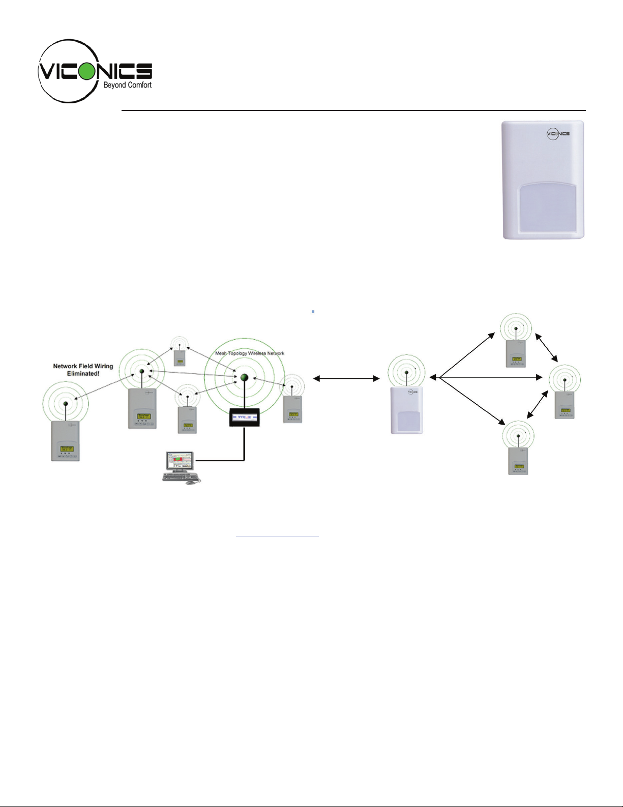
The VRP5000W1000W wireless repeater has been specically designed to be used
within a Viconics wireless ZigBee network for Viconics wireless controllers.
The repeater is intended to be a low cost additional communication component used
when some remote controllers are too far from the main mesh of the Viconics device
cluster and cannot communicate with either:
• A VWG ( Viconics Wireless Gateway )
OR
• A JACE wireless communication card and related WirelessStatNetwork driver le that have been specically designed to
be used by the Niagara AX® powered JACE controllers.
The repeater(s) will enable the remote controller(s) to re-establish communication and act as bridge(s) to the main mesh.
The repeater(s) can be installed where most convenient such as a wall or in a suspended ceiling space if required.
VRP5000W1000W
Repeater
Viconics Controller(s)
Main Mesh Cluster
Remote Viconics
Controller(s) Cluster
The following documentation is available on www.viconics.com
• VWG hardware installation is available in document LIT-VWG-40-INSTALL-Exx
• VWG BACnet integration information is available in document ITG-VWG-40-BAC-Exx
• VWG information on design considerations of a wireless mesh network set-up and diagnostics is available in document
LIT-VWG-40-SETUP-Exx
• JACE2 communication card set-up, integration information and design consideration of wireless mesh networks for setup and diagnostics is available in document MAN-Wireless-Stat-Driver-Guide-Exx
0028-0265-04
www.viconics.com / sales@viconics.com
2
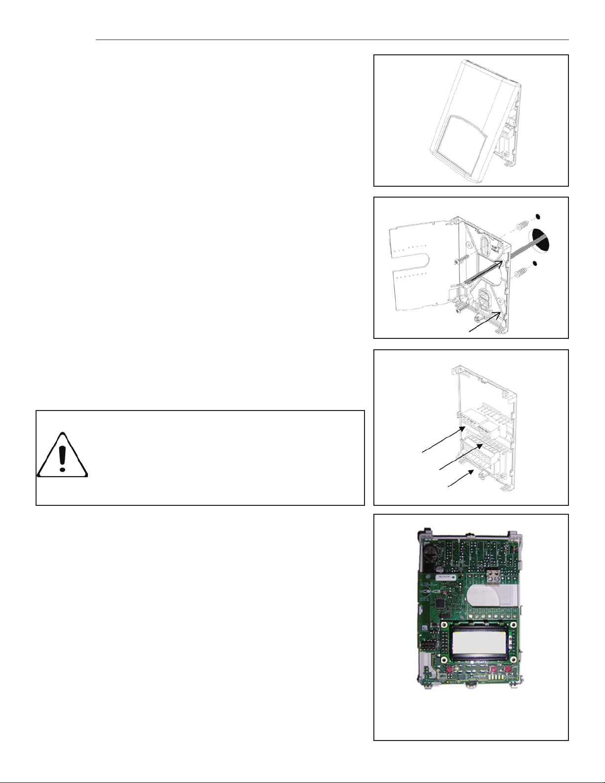
Installation
• Remove security screw on the bottom of repeater cover.
• Open cover by pulling on the bottom edge of repeater.
• Remove assembly and then remove wiring terminals from sticker.
(Fig. 3)
• Please note the FCC ID and IC label installed in the cover upon
removal of cover of the wireless products.
A) Installation ( wall or within suspended ceiling ):
1- Swing open the repeater PCB to the left by pressing the PCB
locking tabs. (Fig. 4)
2- Pull cables 6” out of the wall.
3- Mounting surface must be at and clean.
4- Insert cables in the central hole of the base.
5- Align the base and mark the location of the two mounting holes on
the wall. Install with proper side of base facing up.
6- Install anchors if required.
7- Insert screws in mounting holes on each side of the base.
(Fig. 4)
8- Gently swing back the circuit board on the base and push on it
until the tabs lock.
9- Strip each wire 1/4 inches from end.
10- Insert each wire according to wiring diagram.
11- Gently push excess wiring back into hole (Fig. 5).
12- Re-Install wiring terminals in correct location. (Fig. 5).
13- Reinstall the cover (top side rst) and gently push extra wire length
into the hole in the wall.
14- Install security screw.
Fig. 3
Location of PCB retaining tabs
Fig. 4
Re-install terminal blocks
• Electronic controls are static sensitive devices.
Discharge yourself properly before manipulating and
installing the controller.
• A short circuit or wrong wiring may permanently damage the controller or the equipment.
Fig. 5
Repeater assembly
(VRP5000W)
0028-0265-04
www.viconics.com / sales@viconics.com
3
Basic Initial Design And Deployment Considerations
Proper design considerations need to be addressed prior to installation of a VWG or JACE with a Viconics wireless communication card and related wireless controllers.
1. To properly avoid network interference with 802.11 Wi-Fi devices in the 2.4GHz spectrum range, Viconics recommends the use of 802.15.4 channels 15, 25 and 26 only. 802.11 Wi-Fi transmissions overlap and may interfere with
other channel selection allowed by 802.15.4 (Channels 11 to 24)
2. Maximum distance between each node ( controller(s) or repeater(s)) should be:
• Clear line of sight distance between 2 nodes should be under 100 feet (30 M)
• Non line of sight distance for typical wall gypsum partitions made with metal stud frame should be under 30
feet (10M)
3. Ensure that the minimum distance between any Viconics ZigBee node and any Wi-Fi devices (wireless routers, wireless adapters, lap-tops using wireless networks, etc….) to be at least 3 foot (1 M) and preferably 10 feet (3 M) or
more.
4. Ensure that at least one controller is within 30 feet of the VWG and JACE for every cluster of 10 Controllers installed.
Always try to locate the VWG and JACE near the center of all associated wireless controllers when possible.
5. Always try to locate the VWG and JACE near on in line of sigh to as many wireless controllers as possible.
6. Avoid metal, brick walls or concrete obstructions between wireless devices when possible.
7. Make sure the antenna on the VWG and JACE is always perpendicular to the oor.
8. Avoid placing VWG, JACE and controllers near metal or enclosed in metal boxes. If the VWG and JACE need to be
installed inside a metal cabinet, use the remote antenna accessory.
VRP5000W1000W Deployment Considerations
When Viconics wireless controller nodes cannot be discovered or added to a VWG and JACE database due to distance,
the use of repeaters to bridge communication back to the VWG and JACE becomes necessary.
The number of repeater(s) necessary depends on how many devices are not able to join the VWG and JACE and how
they are organized and distanced from each other.
• Clear line of sight distance between 2 nodes should be under 100 feet (30 M)
• Non line of sight distance for typical wall gypsum partitions made with metal stud frame should be under 30
feet (10M)
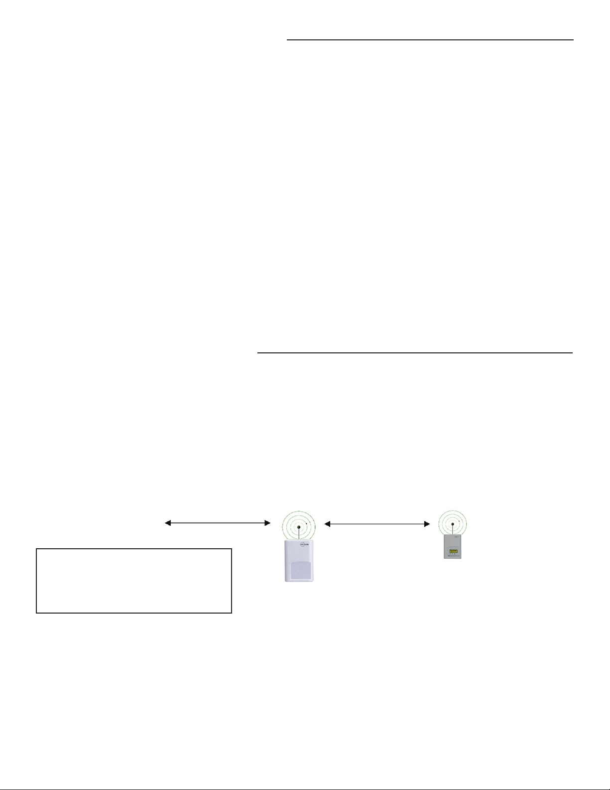
If a single controller is too far away and cannot join the main network a single repeater may be used:
Viconics Controller(s)
Main Mesh Cluster
All distances
Line of sight maximum 100 feet (30 M)
Through partitions maximum 30 feet (31 M)
VRP5000W1000W
Remote Viconics
Controller
Repeater
0028-0265-04
www.viconics.com / sales@viconics.com

4
If a single controller is too far away and cannot join the main network with a single repeater, multiple repeaters
can be used to increase the covered communication distance to the required coverage expected:
Viconics Controller(s)
Main Mesh Cluster
All distances
Line of sight maximum 100 feet (30 M)
Through partitions maximum 30 feet (31 M)
VRP5000W1000W
Repeater
VRP5000W1000W
Repeater(s)
Remote Viconics
Controller
More than 2 can be used
If 2 or more controllers are too far away and cannot join the main network a single repeater may be used as
long as the cluster of devices distanced as recommended for the main network deployment:
Viconics Controller(s)
Main Mesh Cluster
All distances
Line of sight maximum 100 feet (30 M)
Through partitions maximum 30 feet (31 M)
VRP5000W1000W
Repeater
Remote Viconics
Controller(s) Cluster
More than 1 can be used
0028-0265-04
www.viconics.com / sales@viconics.com

5
Repeater Status LED
¾ Be sure all controllers and repeaters connected to a VWG and JACE are using the same PAN ID and Channel as
the JACE wireless communication card.
Repeater Wireless Adapter LED Status Indicators
1 x 200ms short blink Power on
2 x 200ms short blinks Power on and adapter communicating with repeater base
3 x 200ms short blinks Power on, adapter communicating with repeater base and there is connectivity to wire-
4 x 200ms short blinks Power on, adapter communicating with repeater base, connectivity to wireless network
4 x 200ms short blinks and 1 x 1500ms long blink Power on, adapter communicating with repeater base, connectivity to wireless network
System Troubleshooting Recommendations
1. If a repeater is not detected by the VWG and JACE, verify that the LED is blinking at least 4 times. If it is only blinking twice, ensure
that the PAN and Channel of the controller is the same as the VWG and JACE it must communicate with.
2. When commissioning a network, it is recommended to use channels 15, 25 or 26. Alternate these channels between oors.
3. If a particular repeater or controller refuses to join the network and cannot be seen by the VWG and JACE. Please move closer to the
VWG and JACE until it has joined the network and it is added to the database. It can then be re-located to its original position.
less network
and VWG / JACE is communicating with wireless repeater
and VWG is communicating with wireless repeater.
Terminal Block
Two wires power the repeater. No other wiring is required. Simply connect 24 Vac to the terminal block as shown below.
0028-0265-04
www.viconics.com / sales@viconics.com

Installer conguration parameter menu
Conguration is done locally at the repeater.
• To enter conguration, press and hold the Left button for 8 seconds
• Press again the Left button repetitively to scroll between all the available parameters
• Use the (up / right) and (down / middle / center) key to change the parameter to the desired value.
• To acknowledge and save the new value, press the Left button again.
• The next listed parameter is now displayed
Conguration interface
Left Enters the conguration mode. Press and hold for 8 seconds
Pressing repetitively will scroll all available parameters one by one
Middle / Center Adjust / rotate parameter value down
Right Adjust / rotate parameter value up
6
Conguration parameters
Signicance and adjustments
Default value
Com Addr Repeater networking address
Default value = 254
Range is: 0 to 254 Valid range is 0 to 254
PAN ID Personal Area Network Identication
Default value = 0
Range is: 0 to 500
This parameter (Personal Area Network Identication) is used to link specic
controllers or repeaters to a single specic Viconics wireless gateway ( VWG /
JACE ) For every controller or repeater reporting to a gateway be sure you set
the SAME PAN ID value both at the gateway and the wireless device(s).
The default value of 0 is NOT a valid PAN ID. The valid range of available PAN
ID is from 1 to 500
Channel Channel selection
Default value = 10
Range is: 10 to 26
0028-0265-04
This parameter (Channel) is used to link specic controllers or repeaters to
specic Viconics wireless gateway(s) ( VWG / JACE ) For every controller or
repeater reporting to a gateway be sure you set the SAME channel value both at
the gateway and the wireless device(s).
Viconics recommends using only the following channels ( 15, 25 or 26 )
The default value of 10 is NOT a valid channel. The valid range of available
channel is from 11 to 26
www.viconics.com / sales@viconics.com

Specications
Repeater power requirements: 19-30 VAC 50 or 60 Hz; 2 VA Class 2
Operating conditions: 0 °C to 50 °C ( 32 °F to 122 °F )
0% to 95% R.H. non-condensing
Storage conditions: -30 °C to 50 °C ( -22 °F to 122 °F )
0% to 95% R.H. non-condensing
Wire gauge: 18 gauge maximum, 22 gauge recommended
Dimensions: 4.94” x 3.38” x 1.13”
Approximate shipping weight: 0.75 lb ( 0.34 kg )
Agency Approvals all models: UL: UL 873 (US) and CSA C22.2 No. 24 (Canada), File
E27734 with CCN XAPX (US) and XAPX7 (Canada)
Industry Canada: ICES-003 (Canada)
Agency Approvals all models: FCC: Compliant to CFR 47, Part 15, Subpart B, Class A
(US)
CE: EMC Directive 89/336/EEC (Europe Union)
C-Tick: AS/NZS CISPR 22 Compliant (Australia / New
Zealand) Supplier Code Number N10696
FCC: Compliant to: Part 15, Subpart C
THIS DEVICE COMPLIES WITH SECTION 15 OF THE FCC RULES. OPERATION IS SUBJECT TO THE FOLLOWING TWO
CONDITIONS: (1) THIS DEVICE MAY NOT CAUSE HARMFUL INTERFERENCE, AND (2) THIS DEVICE MUST ACCEPT ANY
INTERFERENCE RECEIVED, INCLUDING INTERFERENCE THAT MAY CAUSE UNDESIRED OPERATION.
7
Drawing & Dimensions
Fig.13 – Repeater dimensions
0028-0265-04
9245 Langelier Blvd. I St-Leonard I Quebec I Canada I H1P 3K9
Viconics Technologies Inc.
Tel .: (514) 321.5660 I Fax: (514) 321.4150 Toll free: 1 800.563.5660
sales@viconics.com I www.viconics.com
www.viconics.com / sales@viconics.com
 Loading...