

Page 1
Features
Benefits
Microcomputer-based
Exceptional accuracy and linearity
2% models 10 point calibration
3% models 3 point calibration
Increased accuracy and linearity across the
required control range
Timed RH level status LED
Rapid trouble-shooting and commissioning.
Humidity level is proportional to a 10 second
duty cycle. Ex, using a time clock, if pulse
duration is 6.5 seconds, sensed % RH by
transmitter is 65% RH
Elegant aesthetic design
Blends well in all environments
Various additional temperature
sensor options available
More functionality for DDC system installation
by combining local temperature and humidity
sensing in a single component
Model Output
Accuracy Temperature Sensor
Mounting
Extension
VH2
0 0-5 / 0-10 V
2 +/- 2%
0 None W Wall 1 4-20 mA
3 +/- 3%
1 3K Ohms thermistor
+/- 1%
D Duct 2 10K Ohms Type 2
+/- 1%
E Outdoor
3
10K Ohms Type 3
+/- 1%
4
100K Ohms thermistor
+/- 1% 5
1K Ohm NIFE
6
100 Ohms Platinum
7
1K Ohm Platinum
VH2
0 2 2 W 1000
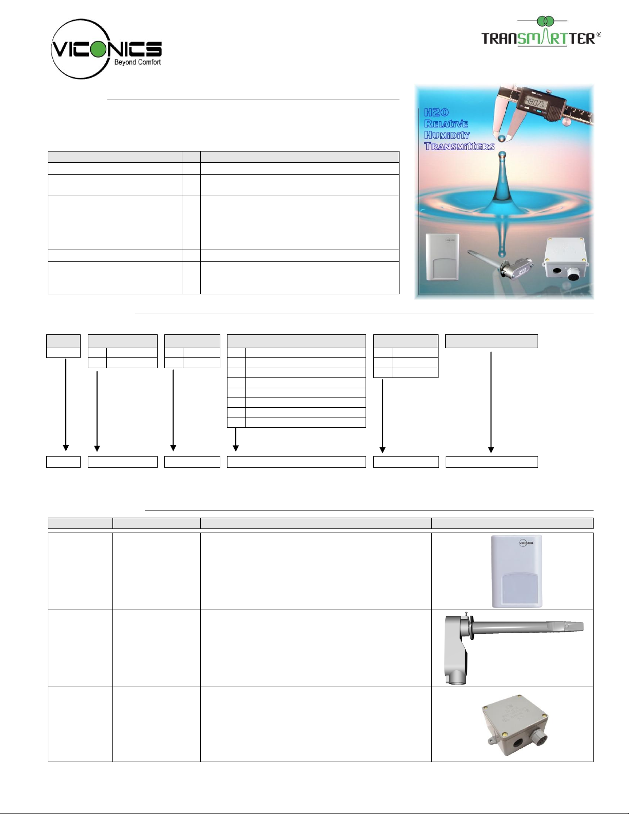
Model:
Description:
Application:
Picture:
VH20 Wall
Room sensor
Remote room humidity sensing
Accessory temperature sensor available
VH20 Duct
Duct sensor with
junction box
Remote return air humidity sensing with the
sensor mounted on the return air duct.
Outside air humidity sensing with the sensor
installed in the fresh air plenum.
Supply air humidity sensor
Accessory temperature sensor available
VH20
Exterior
Outside air
sensor, NEMA 4
enclosure
Outside air humidity sensing with the sensor
installed directly exposed to the elements.
Sensor uses a water resistant NEMA 4 PVC
enclosure for outdoor applications
Accessory temperature sensor available
VH20 Electronic Humidity Transmitter Series
Description
The VH20 series, microcomputer-based humidity transmitters are designed for
accurate humidity sensing in non-corrosive commercial applications such as:
hospitals, schools, office buildings, retail stores, museums and computer rooms.
Available models
Example: Above model is VH2022W1000 for wall mount, 2% accuracy, 0-10 or 0-5 Vdc output with 10K Ohms Type 2
temperature sensor.
Models description
1
Page 2
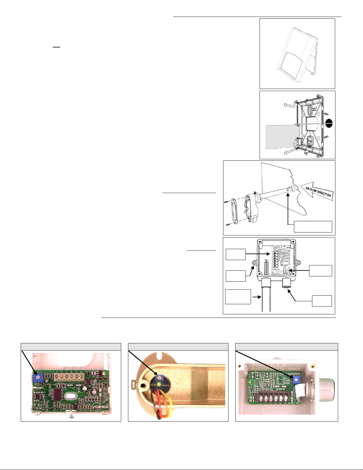
Fig. 2
Installation of room sensors (VH20 Wall) (Fig. 1 & 2)
VH20 Wall mounted
VH20 Duct mounted
VH20 Outdoor
Fig. 1
Fig.3
Probe tip, flat side
facing airflow
Fig.4
Calibration
+/- 5% RH
Sensing
probe
PCV conduit
Adapter by
others
Wiring
terminal
Mounting
hole
Remove security screw on the bottom of sensor cover.
Open up by pulling on the bottom side of sensor. (Fig.1)
Location:
1- Should not be installed on an outside wall.
2- Must be installed away from any heat source.
3- Should not be installed near an air discharge grill.
4- Should not be affected by direct sun radiation.
5- Nothing must restrain vertical air circulation to the sensor.
Installation:
1. Remove security screw on the bottom of thermostat cover.
2. Open up by pulling on the bottom side of thermostat.
3. Pull out cables 6” out of the wall.
4. Wall surface must be flat and clean.
5. Insert cable in the central hole of the base.
6. Flip printed circuit board to access mounting hole
7. Align the base and mark the location of the two mounting holes on the wall.
8. Install proper side of base up.
9. Install anchors in the wall.
10. Insert screws in mounting holes on each side of the base. DO NOT OVERTIGHTEN
11. Strip each wire 1/4 inch.
12. Insert each wire according to wiring diagram.
13. Gently push back into hole excess wring back into the wall.
14. Press back printed circuit board into place
15. Install the cover, top side first
16. Install security screw.
Installation of duct sensors (VH20 Duct) – (Fig.3)
1. Drill 1” [25mm] hole mid height on the side of the duct to insert the probe.
2. Direct the probe so that the flat side of probe tip is facing the airflow.
3. Mark the position of the two holes to be drilled for mounting the sensor on the
duct. Fasten the sensor to the duct with the two self-taping screws ( notincluded ). Do not overtighten!
4. Junction box must be directed downwards or sideways.
5. For best results, locate sensor as far as you can from heating/cooling source.
Installation of outside air sensor (VH20 Outdoor) – (Fig.4)
1. Install sensor using mounting holes on each side.
2. Install on a vertical surface, respect mounting orientation
3. Remove the four screws and remove the cover.
4. Strip each wire 1/4 inch.
5. Insert each wire according to wiring diagram.
6. Install the cover with supplied screws.
7. In snowy area allow sufficient height for snow accumulation.
Maintenance of transmitter
Calibration: The transmitter is factory calibrated. However, it can be field recalibrated by using the ( -5%, 0%, 5% ) potentiometer
inside the transmitter to adjust the zero. The transmitter is already factory calibrated to the center of the potentiometer. To
recalibrate the transmitter to the factory preset, turn the potentiometer to the 0% adjustment. (see pictures below)
Cleaning: The VH20 duct sensor probe needs inspection annually to be cleaned of any excess dirt on the sensing element tip.
The whole filter tip can be ordered and replaced if it cannot be cleaned properly. Part number: VH20DuctTip.
Page 3

0 to 10 Vdc / 0 to 5 Vdc output models
4 wires / terminals
0 to 10 Vdc / 0 to 5 Vdc output models
With optional temperature sensor
6 wires / terminals
4 to 20 mA output models
2 wires / terminals
4 to 20 mA output models
With optional temperature sensor
4 wires / terminals
-2
% R.H.
+2% R.H.
Reference
10 20 604030 50 70 80 90
Typical Calibration Curve 2% Model
% R.H.
Vdc Power (+) 12-30 Vdc
4 to 20 mA Output
VH20 Duct model
Red
Black
VH20 Wall and Outdoor models
2
1
Vdc Power (+) 12-30 Vdc
4 to 20 mA Output
2
1
VH20 Wall and Outdoor models
561
2
Temperature sensor
Temperature sensor
4 to 20 mA Output
Vdc Power (+) 12-30 Vdc
6
512
4 to 20 mA Output
Temperature sensor
Temperature sensor
Vdc Power (+) 12-30 Vdc
White
VH20 Duct model
Black
White
Red
VH20 Wall and Outdoor models
6
54321
Temperature sensor
Temperature sensor
6
5
0 to 10 Vdc Output
0 to 5 Vdc Output
Power (+) 12-30 Vdc / 24 Vac
Common (-)
243
1
VH20 Wall and Outdoor models
1
342
0 to 10 Vdc Output
0 to 5 Vdc Output
Power (+) 12-30 Vdc / 24 Vac
1
Common (-)
342
Power (+) 12-30 Vdc / 24 Vac
0 to 10 Vdc Output
0 to 5 Vdc Output
Orange
Black
Yellow
Red
VH20 Duct model
Common (-)
Temperature sensor
Temperature sensor
White
White
0 to 5 Vdc Output
Power (+) 12-30 Vdc / 24 Vac
0 to 10 Vdc Output
Orange
VH20 Duct model
Red
Yellow
Black
Common (-)
Typical calibration curve
The VH20 2% series, microcomputer-based humidity transmitters are calibrated with a 10 point curve with each point
equally spread from 10% to 90%
Wiring of VH20 transmitter
3
Page 4

Specifications:
Power supply
Vdc models output
Linear output 0 to 10 Vdc / 0 to 5 Vdc into 2K resistance min.
24 Vac / Vdc -15%, +10% Vac 50/60 Hz; 1 VA
Power supply
4-20 mA models output
Linear output 4 to 20 mA
12-30 Vdc
Calibration
10 point for 2% models; 3 point for 3% models
Humidity sensing element
10 points calibrated bulk polymer type sensor
Temperature effect
% RH is temperature compensated. Effect is less than 0.1% over the full range (0-100%)
Stability
Less than 1.0 % yearly (typical drift)
Field calibration
-5% / 0% factory / +5% trimmer
Optional temperature sensor
1 % accuracy typical
Maximum wire length
5,000 feet [1,525 m] for 24 GA wire and up
Warranty
18 months from date of purchase or 12 months from date of installation
Operating conditions:
32 F to 122 F ( 0 C to 50 C )
0% to 95% R.H. non-condensing
Time constant:
Less than 1 minute at 63%
Storage conditions:
-22 F to 122 F ( -30 C to 50 C )
0% to 95% R.H. non-condensing
Dimensions:
(refer to drawing Fig.5)
Appr. shipping weight:
0.4 LBS (0.2 kg )
Enclosure plastic type:
ABS - FRI [WT1337V] UV stabilized
Operating conditions:
-40 F to 122 F ( -40 C to 50 C )
0% to 95% R.H. non-condensing
Time constant:
Less than 10 seconds at 63%
Min. 100 FPM max. 1200 FPM
Storage conditions:
-40 F to 122 F ( -40 C to 50 C )
0% to 95% R.H. non-condensing
Dimensions:
(refer to drawing Fig.6)
Appr. shipping weight:
0.8 LBS [0.4 Kg]
Probe tip plastic type:
Fire retardant grade "HB" ABS
Operating and storage
conditions:
-40 F to 122 F ( -40 C to 50 C )
0% to 100% R.H.
Time constant:
Less than 1 minute at 63%
Dimensions:
(refer to drawing Fig.7)
Appr. shipping weight:
1.3 LBS [0.6 Kg]
Enclosure plastic type:
NEMA 4 PVC
Viconics Technologies Inc. 9245, Langelier Blvd, St-Leonard, Quebec, Canada H1P 3K9
028-0116
www.viconics.com
sales@viconics.com
1/2" [13 mm] FPT
Ø 0.75" [19 mm]
7.00" [178 mm]
1.30" [33 mm]
4.40" [112 mm]
1.75" [44 mm]
2.10" [53 mm]
Ø 5/32" [4 mm]
c/c 1.75" [44mm]
Fig.6
4.00"
[102 mm]
4.88" [124 mm]
3.45"
[88 mm]
3.67" [93 mm]
* Threaded
brass insert
Ø 8-32*
Ø 0.25"
[6 mm]
Ø 7/8"
[22 mm]
1.63"
[42 mm]
c/c 4.68" [119 mm]
5.25" [133 mm]
1.19" [30 mm] 1.19" [30 mm]
2.00"
[51 mm]
4.00" [102 mm]
3.45" [88 mm]
0.25" [6 mm]
2.125"
[54 mm]
Fig.7
Fig.5
3.38" [86 mm]
1.13" [29 mm]
4.94" [125 mm]
General for all sensors
Room sensors (VH20 Wall) (Fig.5)
Duct sensor (VH20 Duct) (Fig.6)
Outside air sensor (VH20 Exterior) (Fig.7)
Notes:
Humidity sensor is suitable for normal clean air.
Not to be used in corrosive or harmful environment.
Specifications and equipment are subject to change without prior
notice.
Important notice
undergone rigorous tests and verifications prior to shipment to ensure
proper and reliable operation in the field. Whenever a control failure
could lead to personal injury and/or loss of property, it becomes the
responsibility of the user / installer / electrical system designer to
incorporate safety devices ( such as relays, flow switch, high and low
limits, thermal protections, etc…) and/or alarm system to protect the
entire system against such catastrophic failures. Tampering of the
devices or mis application of the device will void warranty.
All VH20 series sensors are for use as operating controls
only and are not safety devices. These instruments have
05/04/12 LIT-VH20X-E06.doc
 Loading...