

Page 1
VCM7000 Series
Accessory Communication Module
Installation Guide
For VT(R)7000 Series Controllers
May 16th 2011 / 028-0344-R1
Contents
Description 2
Models Available 2
Installation 3
Module Installation 3
Specications 4
VCM7000 Series-Installation Guide1 |
Page 2
Description
All current “Network Ready” Viconics VT(X)7000 ( 5000 Series ) controllers purchased
after July 2010 are capable of being retrot in the eld with accessory communication
adapters that enables the controllers to be integrated into virtually all leading building
automation system.
This approach allows the exibility to add network communication strategies as budgets allow or as the buildings needs change.
The manufacturing date is identied inside the controller on a small label which also
contains the part number. The format of the date code is year / week. If in doubt,
please contact the factory for assistance. Always verify the manufacturing date code
of all thermostats before ordering any communication modules.
Ex.: VTR7355A5500, date code is 1115 manufactured in
2011 during the 15th week of the year at the beginning of
April.
If required, Network Ready ( Stand-Alone ) Terminal Equipment Controllers can be
eld retrotted with the following communication adapters
Models Available
MODEL DESCRIPTION
VCM7000V5000W Wireless Retrot Communication Card for all VT7000 & VTR7000 Series
VCM7000V50xxP Wireless Retrot Communication Card for all VT7000 & VTR7000 Series
VCM7300V5000B BACnet Retrot Communication Card for all VT7200 & VT7300 Series
VCM7600V5000B BACnet Retrot Communication Card for all VT7600 Series
VCM7607V5000B BACnet Retrot Communication Card for all VT76x7 with RH
VCM7300T5000B BACnet Retrot Communication Card for all VTR7300 Series
VCM7300V5000E Echelon Retrot Communication Card for all VT7200 & VT7300 Series
VCM7600V5000E Echelon Retrot Communication Card for all VT7600 Series
VCM7607V5000E Echelon Retrot Communication Card for all VT76x7 with RH
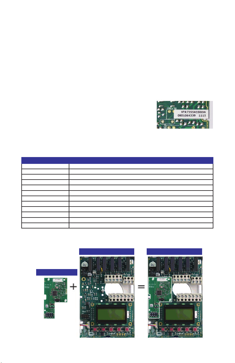
Network Ready Controller Wireless Network Controller
Wireless Communication Card
VCM7000 Series-Installation Guide2 |
Page 3

installation
Remove the security screw on the bottom of
Terminal Equipment Controller cover.
• Open unit by pulling on the bottom
side of Terminal Equipment Controller
(g. 1).
• Remove power to the unit by
disconnecting to top left terminal block.
• Ensure power is down by conrming
the local display is not operating.
Module Installation
1. Align module connector and the 2
retaining pins on their respective
insertion points of the controller base.
2. Insert connector and the 2 retaining
pins all at once by pressing on the 3
location simultaneously. (g. 2).
3. Make sure retaining pins are properly
snapped in place.
4. A misalignment of the module
connector while the controller is
powered may permanently damage
the Terminal Equipment Controller or
the communication module
5. Power back the unit by reconnecting
the top left terminal block.
6. Re-install the cover (top side rst)
7. Re-install security screw
Fig. 1
Fig. 2
• Electronic controls are static sensitive devices. Discharge yourself properly
before manipulating and installing the Terminal Equipment Controller.
• A misalignment of the module connector while the controller is powered
may permanently damage the Terminal Equipment Controller or the
communication module.
• All VT(R)7000 series controls are designed for use as operating controls
only and are not safety devices. These instruments have undergone rigorous
tests and verication prior to shipping to ensure proper and reliable operation
in the eld. Whenever a control failure could lead to personal injury and/or
loss of property, it becomes the responsibility of the user / installer / electrical
system designer to incorporate safety devices ( such as relays, ow switches,
thermal protections, etc…) and/or alarm systems to protect the entire system
against such catastrophic failures. Tampering with the devices or unintended
application of the devices will result in a void of warranty.
VCM7000 Series-Installation Guide3 |
Page 4

specifications
Operating conditions: 0 °C to 50 °C ( 32 °F to 122 °F )
Storage conditions: -30 °C to 50 °C ( -22 °F to 122 °F )
Approximate shipping weight: 0.75 lb ( 0.34 kg )
Agency Approvals all models: UL: UL 873 (US) and CSA C22.2 No.
Agency Approvals all models: FCC: Compliant to CFR 47, Part 15,
Agency Approvals Wireless models: FCC: Compliant to: Part 15, Subpart C
0% to 95% R.H. non-condensing
0% to 95% R.H. non-condensing
24 (Canada), File E27734 with CCN
XAPX (US) and XAPX7 (Canada)
Industry Canada: ICES-003 (Canada)
Subpart B (US)
CE : EMC Directive 89/336/EEC (Eu-
rope Union)
C-Tick: AS/NZS CISPR 22 Compliant
(Australia / New Zealand) Supplier
Code Number N10696
Viconics Electronics Inc.
9245 Langelier Blvd. I St-Leonard I Quebec I Canada I H1P 3K9
Tel .: (514) 321.5660 I Fax: (514) 321.4150 Toll free: 1 800.563.5660
sales@viconics.com I www.viconics.com
VCM7000 Series-Installation Guide4 |
 Loading...