

Page 1
VC 3000 Series
Line Voltage Switching
Relay Pack Controllers
Installation Guide
For Commercial and Lodging HVAC
Fan Coil Applications
May 3rd, 2012 / 028-0296-R6
CONTENTS
Installation 2
Communication Wiring to VTR73xxA 4
Terminal Equipment Controller 4
VC3xxx LED Operation 5
Wiring of Remote Inputs to VC3504E and VC3404E 6
Model Chart 7
Terminals, Wire Identification & Ratings 8
Typical Wiring Example 9
Specifications 9
Dimensions 10
Important Notice Error! Bookmark not defined.
1 VC7300 Series-Installation Guide
Page 2
INSTALLATION
IMPORTANT: ALL WIRING MUST CONFORM TO LOCAL
AND NATIONAL ELECTRICAL CODE REGULATIONS.
Please read the following instructions carefully before proceeding with the
installation. Failure to follow the instructions could damage the product or
cause a hazardous condition. Installation must be performed by a qualified
service technician or electrician. Disconnect power supply before installing in
order to prevent electrical shock.
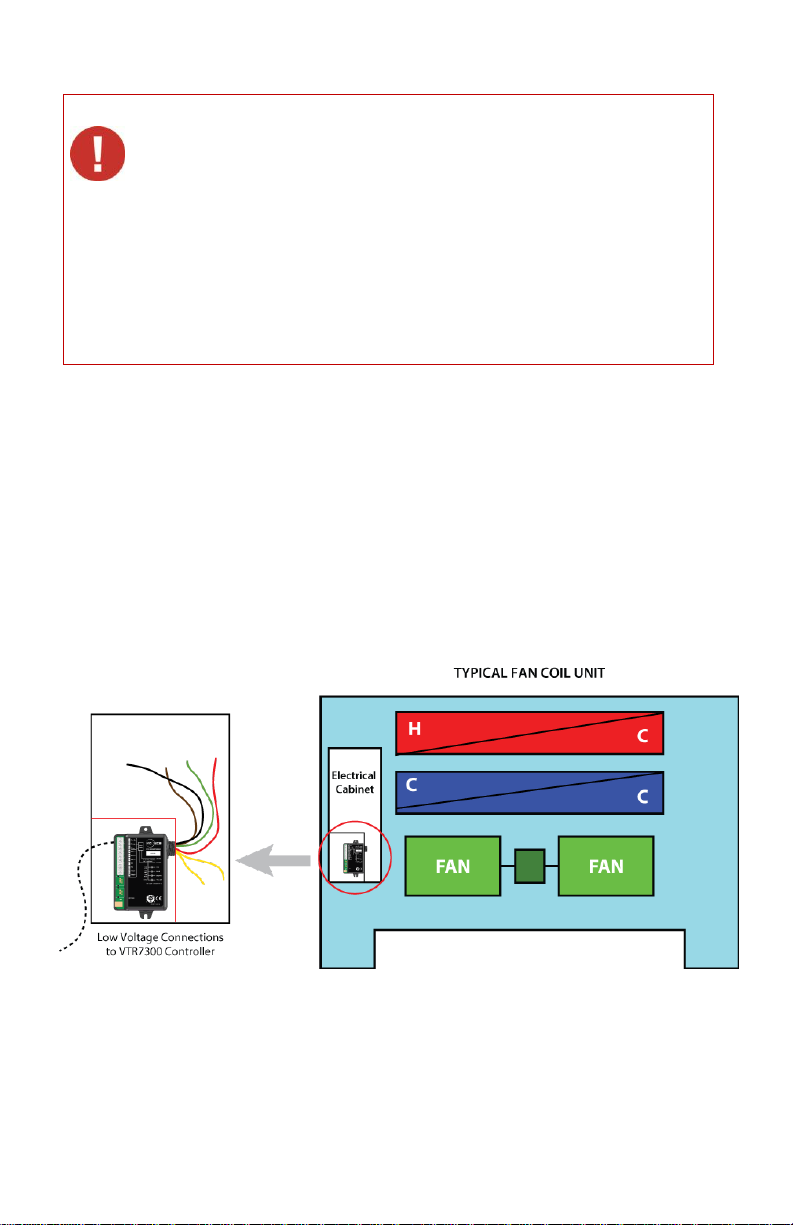
There are three basic methods for installing the VC3000 transformer relay pack controller.
A) Inside an electrical cabinet of a fan coil unit
• Use the plastic mounting tabs to secure the unit to the inside of the electrical enclosure.
• Secure to the inside with screws.
• Cut one or both plastic mounting tabs if space is needed inside the enclosure.
• Install a low voltage or high voltage metal separator if required.
• Do not exceed the maximum rated temperature of the unit. (50 °C/122 °F)
2 VC7300 Series-Installation Guide
Page 3
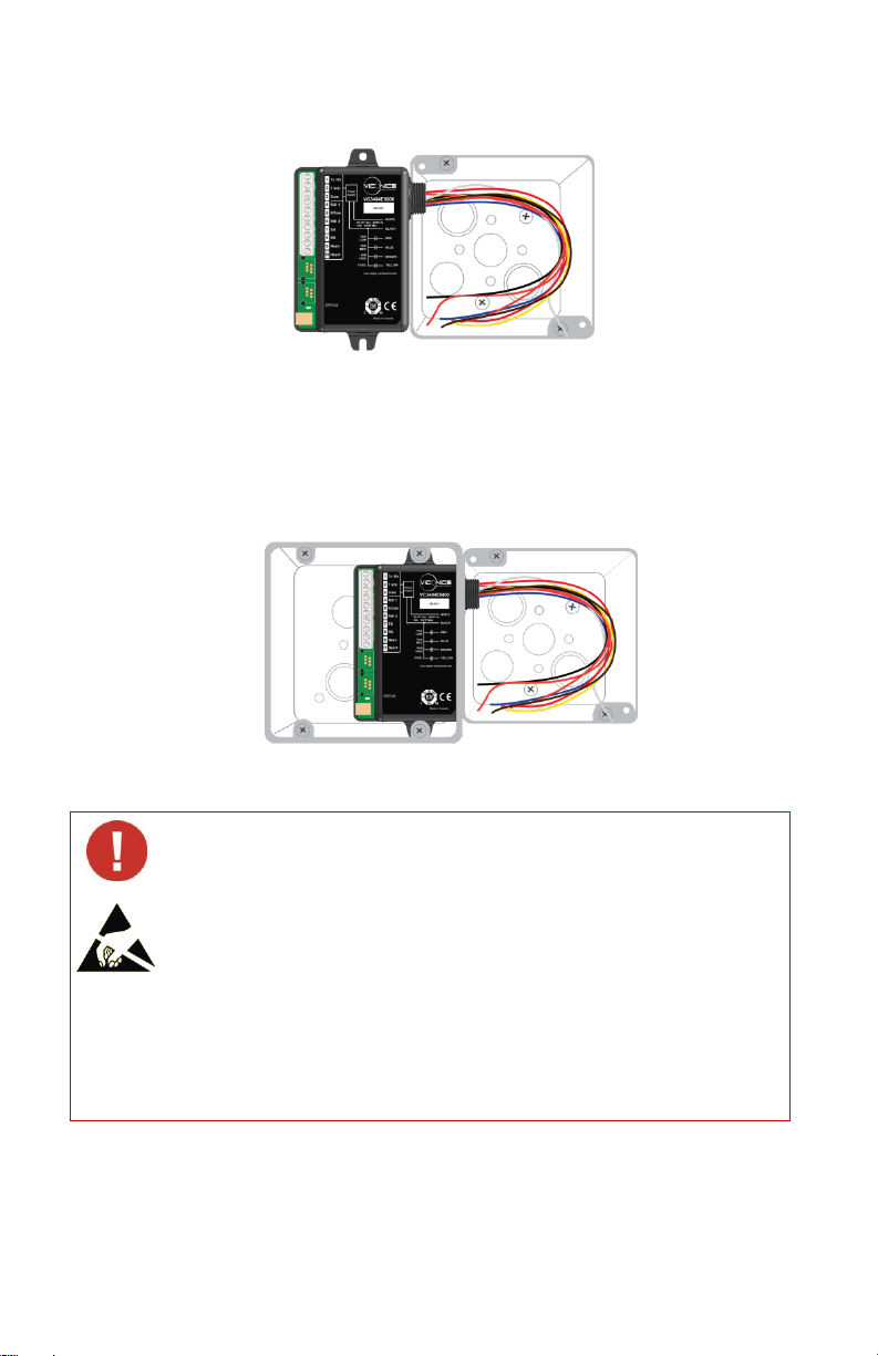
B) Outside of a junction box or electrical cabinet
If replacing an old line voltage fan coil controller, label the wires
before removal of the old controller.
Electronic controls are static sensitive devices. Discharge yourself
of any electrostatic build-up before manipulating or installing the
terminal equipment controller.
A short circuit or wrong wiring may permanently damage the
terminal equipment controller or the equipment.
VC3000 series transformer relay packs are to be used only as
operating controls. If installed incorrectly the intended application may
fail or lead to personal injury or loss of property. It is the responsibility
of the end user to ensure that the device has been properly installed
by a certified professional and that proper safety precautions have
been taken to protect against failures.
• Use the supplied lock nut to secure the transformer relay pack to the electrical junction
box or to the electrical cabinet of the fan coil unit.
C) Enclosed low voltage junction box type installation (if required by local codes)
• Install the transformer relay pack inside a 4”x 4” junction box.
• Cut one or both plastic mounting tabs if space is needed inside the enclosure.
• Use the supplied lock nut to secure the transformer relay pack (inside its junction box) to
the main electrical junction box or to the electrical cabinet of the fan coil unit.
3 VC7300 Series-Installation Guide
Page 4

COMMUNICATION WIRING TO VTR73XXA
TERMINAL EQUIPMENT CONTROLLER
Only one VC3xxxX relay pack with remote monitoring inputs can be used under a single
VTR73xxA controller. All other slave units must be either VC3xxxX relay pack(s)
WITHOUT remote inputs. A maximum of 10 VC3xxxX relay packs can be used for a
single VTR73xxA terminal equipment controller.
From the VTR73xxA to the first VC3xxxX
o Existing or new field wires
o 3 minimum required 14-22 Ga solid or stranded. Shield not necessary.7
From the first VC3xxxX to the controller to all other VC3xxxX Relay Pack(s)
o Existing or new field wires
o 2 minimum required 14-22 Ga solid or stranded. Shield not necessary.
o Connect only common and 2 Tx / Rx communication
4 VC7300 Series-Installation Guide
Page 5

Possible network wiring topology
Condition of the Status LED
Cause
Solution
2 short blinks
No communication between
the VTR73xxA and the
VC3xxxX relay pack. The
VC3xxxX Relay Pack will
resume its output “no
communication active” status
Check communication
wiring and or power
cycle the controllers
2 short blinks and a
longer blink
Normal communication
between the VTR73xxA and
the VC3xxxX relay pack.
N/A
0.2
2.5
0.6
0.4
0.0
1.0
5.0 sec
Power On
Online to
VTR73xxA
The VTR7300 to VC3000 transformer relay pack can use any network wiring topology as
required or based on topology of existing wires.
VC3XXX LED OPERATION
Condition of the status LED
5 VC7300 Series-Installation Guide
On/off LED vs. time (normal operation)
Page 6

WIRING OF REMOTE INPUTS TO VC3504E AND VC3404E
6 VC7300 Series-Installation Guide
Page 7

MODEL CHART
Part #
VC3500E5000
VC3504E5000
VC3514E5000
Occ. Output
VC3400E5000
VC3404E5000
VC3300E5000
Slave Fan
Unit
Applications
2 pipes
2 pipes with
reheat
4 pipes
2 pipes
2 pipes with
reheat
4 pipes
2 pipes
2 pipes with
reheat
4 pipes
2 pipes
2 pipes with
modulating
pulsed reheat
2 pipes
2 pipes with
modulating
pulsed reheat
Slave fan
control only
Fan control
Up to 3 speed
Up to 3 speed
Up to 3 speed
Up to 3 speed
Up to 3 speed
Up to 3 speed
Monitoring
inputs
None
4 FCU remote
inputs
4 FCU remote
inputs
None
4 FCU remote
inputs
None
Control
types
On-Off line
switched valve
output control
- 1 heat / cool
output
- 1 cool output
- 3 fan outputs
On-Off line
switched valve
output control
- 1 heat / cool
output
- 1 cool output
- 3 fan outputs
On-Off line
switched valve
output control
- 1 heat / cool
output
- 1 cool output
- 3 fan outputs
- Occupancy
output
On-Off line
switched valve
output control
- 1 heat / cool
output
- 1 Modulating
pulsed Vdc
output for SSR
electric reheat
control
- 3 fan outputs
On-Off line
switched valve
output control
- 1 heat / cool
output
- 1 Modulating
pulsed Vdc
output for SSR
electric reheat
control
- 3 fan outputs
Slave fan
control only
3 fan outputs
Ordering Information Notes:
Please refer to the “Operation overview” section for related information on VTR73xxA and
VC3xxxX arrangements and possible combinations.
More than one VC3xxxX Relay Pack can be used for a single VTR73xxA Terminal
Equipment Controller.
Only one VC3x4X Relay Pack with monitoring inputs can be used for a single VTR73xxA
Terminal Equipment Controller
Ordering examples:
A VC3500E5000 is for a 90 to 277 Vac powered FCU mounted Relay Pack with the
following outputs:
Three 90 to 277 Vac switching fan relay outputs
Two 90 to 277 Vac switching valve relay outputs
A VC3504E5000 is for a 90 to 277 Vac powered FCU mounted Relay Pack with the
following inputs and outputs:
One configurable universal input
One configurable binary input
One dedicated discharge air temperature monitoring input
One dedicated return air temperature control input
Three 90 to 277 Vac switching fan relay outputs
Two 90 to 277 Vac switching valve relay outputs
A VC3300E5000 is for a 90 to 277 Vac powered FCU mounted Relay Pack with the
following outputs:
Three 90 to 277 Vac switching fan relay outputs
7 VC7300 Series-Installation Guide
Page 8

TERMINALS, WIRE IDENTIFICATION & RATINGS
Part #
VC3500E5000
VC3504E5000
VC3514E5000
Occupancy
Output
VC3400E5000
VC3404E5000
VC3300E5000
Slave Fan Unit
Low
Voltage
Terminals
No local inputs
Low voltage
inputs
Low voltage
inputs
No local inputs
Low voltage
inputs
No local inputs
1
1- Tx/Rx
1- Tx/Rx
1- Tx/Rx
1- Tx/Rx
1- Tx/Rx
1- Tx/Rx
2
2- 7 VDC
2- 7 VDC
2- 7 VDC
2- 7 VDC
2- 7 VDC
2- 7 VDC
3
3- Com
3- Com
3- Com
3- Com
3- Com
3- Com
4
4- RUI 1
4- RUI 1
4- RUI 1
5
5- Scom
5- Scom
5- Scom
6
6- RBI 2
6- RBI 2
6- RBI 2
7
7- SS
7- SS
7- SS 8 8- RS
8- RS
8- RS
9
9-Occ
9- Heat -
9- Heat -
10
10- Heat +
10- Heat +
LINE VOLTAGE CONNECTIONS
Power
Supply
Power supply: - 90 to 277 VAC universal all models
- Black Hot L1 Power VAC(Switches: Brown, Blue, Red, and Yellow)
- White neutral power VAC
Fan line
voltage
contact
Wire
connection
½ HP
Maximum
3 Fan Speed
Control Wires
Brown, Blue,
Red
3 Fan Speed
Control Wires
Brown, Blue,
Red
3 Fan Speed
Control Wires
Brown, Blue,
Red
3 Fan Speed
Control Wires
Brown, Blue,
Red
3 Fan Speed
Control Wires
Brown, Blue,
Red
3 Fan Speed
Control Wires
Brown, Blue,
Red
Valve line
voltage
contact
output
Yellow
wire
connection
10A
maximum
4 Pipes Cool
output
Or
2 Pipes Heat /
Cool output
4 Pipes Cool
output
Or
2 Pipes Heat /
Cool output
4 Pipes Cool
output
Or
2 Pipes Heat /
Cool output
2 Pipes Heat /
Cool output
2 Pipes Heat /
Cool output
N/A
Valve line
voltage
isolated
contact
output
2 x Orange
wires
connection
10A
maximum
4 Pipes Heat
output
Or
2 Pipes reheat
output
4 Pipes Heat
output
Or
2 Pipes reheat
output
4 Pipes Heat
output
Or
2 Pipes reheat
output
N/A
N/A
N/A
8 VC7300 Series-Installation Guide
Page 9

TYPICAL WIRING EXAMPLE
Output ratings:
-Heat Valve: (Orange wire):
10 Amps @ 277 VAC maximum
-Cool Valve: (Yellow wire):
5 Amps @ 277 VAC maximum
-Fan: (red, blue, brown
wire(s)):
1/2 HP @ 277 VAC maximum
Operating conditions:
0C to 50C (32F ro 122F)
0% to 95% RH non-condensing
Approximate shipping
weight:
0.75lb (0.34kg)
Agency approvals all models:
cTUVus: UL 873 (US) and CSA C22.2 No. 24
(Canada)
CE: LVD 2006/95/EC (Europe Union)
CE: EMC 2004/108/EC (Europe Union)
CE for RF: RTTE 1999/5/EC
FCC: Compliant to: Part 15, Subpart B
FCC for RF: Compliant to: Part 15, Subpart C
SPECIFICATIONS
Power Supply: 90 to 277 VAC universal, 50-60 Hz
Fan line voltage contact electrical ratings: Brown, Blue, Red wires ½ HP maximum
Main heat and cool line voltage contact electrical ratings: Yellow wire 10A maximum
Isolated heat line voltage contact electrical ratings: Orange wires 10A maximum
9 VC7300 Series-Installation Guide
Page 10

DIMENSIONS
VC3000 series transformer relay packs are to be used only as
operating controls. If installed incorrectly the intended application may
fail or lead to personal injury or loss of property. It is the responsibility
of the end user to ensure that the device has been properly installed
and that proper safety precautions have been taken to protect against
possible failures. Tampering with the devices or incorrect application
of the device will void warranty.
Viconics Technologies Inc.
Tel.: Fax: Toll free:
WWW.VICONICS.COM
IMPORTANT NOTICE
Please check with your local government for instruction on disposal of this product
10 VC7300 Series-Installation Guide
 Loading...