

Page 1
Door/Window Sensor Installation Guide
Procedure to Install Door/Window Motion Sensor
Page 2
Installation Guide
Door/Window Sensor
INSTALLATION
This procedure shows you how to install a Door/Window Sensor.
Complete the following steps to correctly install the Door/Window Sensor:
1. Install battery.
NOTE: ensure battery polarity is correct.
NOTE: When batteries are first installed, the sensor automatically goes into pairing mode. Refer to the
Room Controller pairing procedure for commissioning.
2. Pull plastic tab
3. Install Sensor Housing.
4. Install Magnet.
5. Install Sensor.
Location
Always consider the following location constraints before installing Door/Window Sensor:
1. Do not install in areas with direct heat source.
2. Do not install near any air discharge grill.
3. Do not install in areas exposed to direct sunlight.
4. Ensure Sensor has sufficient air circulation.
2
5. Ensure ceiling surface is flat and clean.
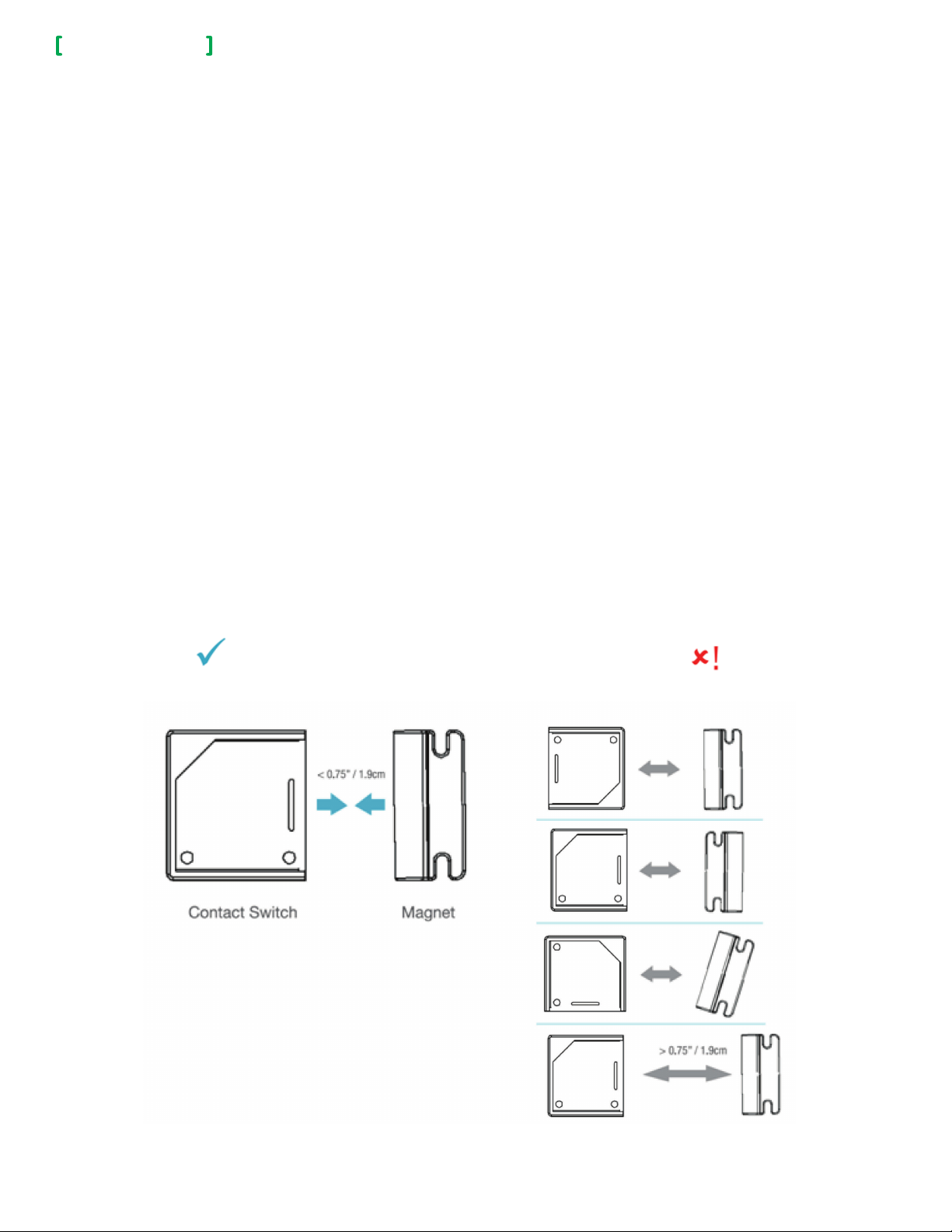
Sensor Placement and Orientation
Ensure Door/Window Sensor and Magnet face each other as shown in below illustration. The Magnet and Sensor
can be a maximum of 0.75in (1.9cm) apart. If aligned properly, you will hear a ‘click’ when they approach.
Correct Alignment
The below shows you how to correctly align the Door/Window Sensor.
Incorrect Alignment
Viconics Technologies Inc. | 9245 Langelier Blvd. | St.-Leo nard | Quebec | Canada | H1P 3K9 | Tel: (514) 321-5660 | Fax: (514) 321-4150
028-6076-00 www.viconics.com | sales@viconics.com October 2014
© 2014 Viconics. All rights reserved.
Page 3

Installation Guide
Door/Window Sensor
BATTERY REPLACEMENT
Pull tab and slide open top Housing of Door/Window Sensor to access old
battery (Figure 1).
NOTE: battery does not come out easily. Use plastic tool to gently pry battery
out of unit. Never use any metal tool to perform this procedure as it may cause
a short circuit or cause damage to Device.
1. Install one CR2032 battery in Housing top (Figure 2).
NOTE: ensure battery polarity is correct.
3
Figure - 1 Figure - 2
INSTALL SENSOR HOUSING
This procedure shows you how to install the Door/Window Sensor to the desired
location. You can use one of the following two options to install the Door/Window
Sensor:
• 2-sided tape
• Screws
Note orientation in illustration.
Option 1
1. Affix 2-sided tape to desired location (Figure 3).
2. NOTE: ensure tape is flush with surface and securely affixed to surface.
3. Set Sensor on 2-sided tape and press firmly to secure Sensor in place.
4. Test Sensor. Refer to "Device Function" on page 4.
Option 2
1. Using screwdriver, secure Sensor to desired location with two screws (Figure 4).
NOTE: ensure screws are tight and Sensor does not move easily. Do not torque
screws.
2. Test Sensor. Refer to "Device Function" on page 4.
Figure 3
• Always test Device before leaving job site.
• Avoid installing Device directly on metal surfaces.
Installation on metal can reduce transmission range.
• Ensure Device is installed in dry location away from
water, moisture, and rain.
Viconics Technologies Inc. | 9245 Langelier Blvd. | St.-Leo nard | Quebec | Canada | H1P 3K9 | Tel: (514) 321-5660 | Fax: (514) 321-4150
028-6076-00 www.viconics.com | sales@viconics.com October 2014
Figure 4
© 2014 Viconics. All rights reserved.
Page 4

Installation Guide
Door/Window Sensor
INSTALL MAGNET
This procedure shows you how to install the Magnet to the desired location. You
can use one of the following two options to install the Magnet:
• 2-sided tape
• Screws
Install Magnet in the proper orientation using 2-sided tape or screws. The Magnet
must be within 0.75in (1.9cm) of the Sensor. If using 2-sided tape, the Magnet’s
tab can be removed by snapping the screw tab along the scored line (Figure 1).
Option 1
1. Affix 2-sided tape to desired location.
NOTE: ensure tape is flush with surface and securely affixed to surface.
2. Set Magnet on 2-sided tape and press firmly to secure Magnet in place.
Option 2
1. Using screwdriver, secure Magnet to desired location with two screws.
NOTE: Ensure screws are tight and Sensor does not move easily. Do not
torque screws.
4
Figure 1
DEVICE FUNCTION
Function and LED Indicators
BUTTON LED ACTION LED DESCRIPTION
Joined
2 times GG Network Status
4 Times GGGG Network Join
8 Times
10 Times
GGGGGGGG
GGGGGGGGGG
G = Green
Y = Yellow
R = Red
Forced Re-Join YYY Re-Join, Searching for Parent
Network leave and join a
new Network
No Action
Power Up RRYYGG
GGG
RRR Not Joined
YYY Re-Join in Process
YRY
YGY Device Being Configured
GGG Device Joined
RRR Device Failed to Join
RRR Leave if Joined
GGGGG Defaults Restored
Y Wrong Button Press
YGR Device Busy
Searching for Network
Viconics Technologies Inc. | 9245 Langelier Blvd. | St.-Leo nard | Quebec | Canada | H1P 3K9 | Tel: (514) 321-5660 | Fax: (514) 321-4150
028-6076-00 www.viconics.com | sales@viconics.com October 2014
© 2014 Viconics. All rights reserved.
 Loading...