

Page 1
SED-WIN / SED-DOR
Wireless Door and Window Switch
Installation Guide
CONTENTS
Installation 2
Self Testing 2
Location 2
Operation Overview 3
Model Chart 3
Pairing Process Procedure 4
Configuring Actions 4
Using VT8000 Controllers for Stand-alone Systems 4
Using VT8000 Controllers for Networked Systems 6
Important Notes Before Starting Pairing Procedure 7
Pairing – Associating Switches with Controllers 8
Multiple Switch Configuration 8
Troubleshooting Guide 9
Status and Monitoring 9
Battery Status 10
Specifications 10
Drawing and Dimensions 11
Marking Templates for Mounting 12
Page 2
2
Wireless Door/Window Switch
INSTALLATION SED-WIN & SED-DOR
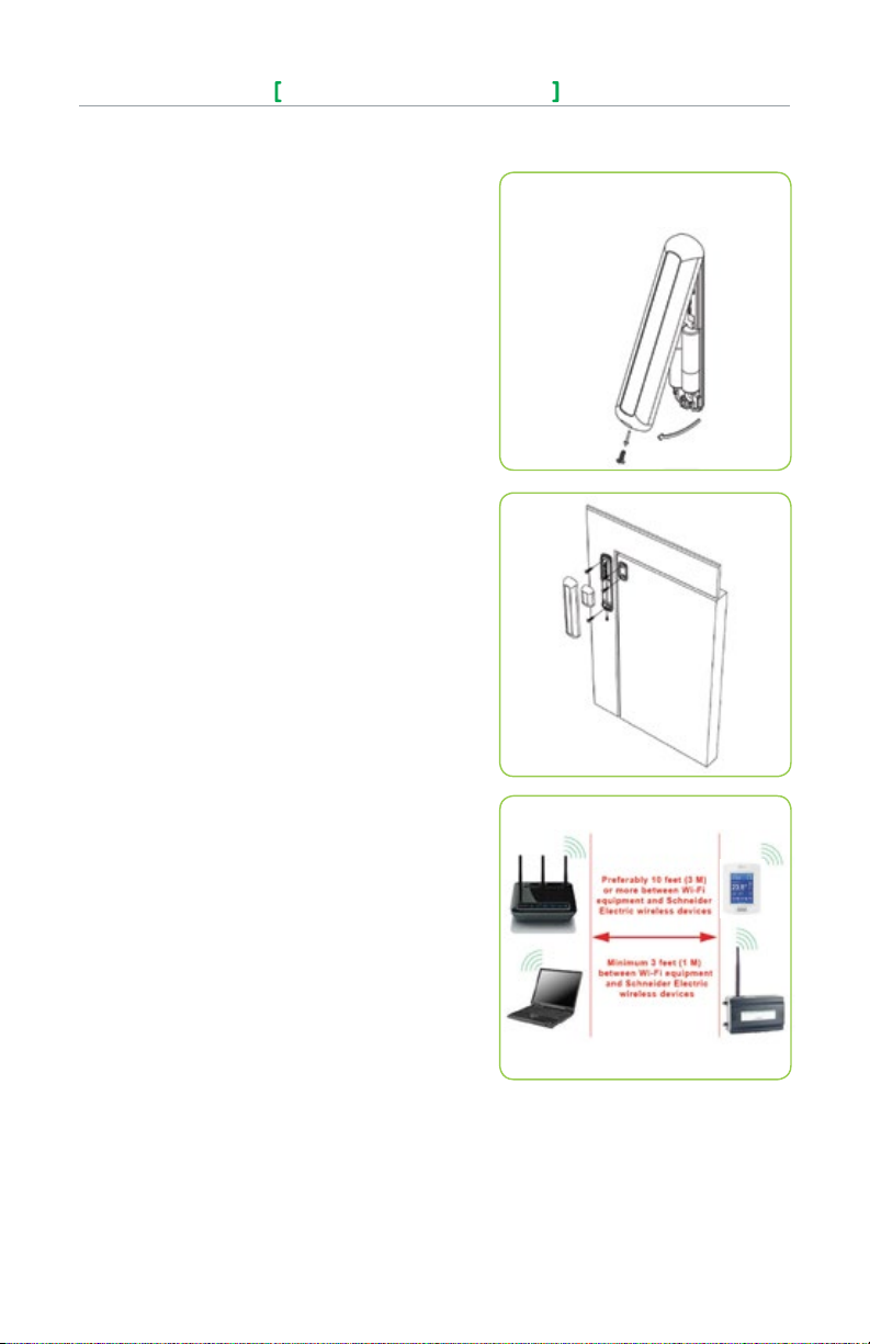
Installation
1. Remove cover by pulling on side where security screw was
mounted (Figure-1).
2. Remove cover of magnet unit.
3. Read FCC ID and IC label inside removed cover.
4. Cut out mounting template (end of this manual) for install. Do not
place it on hinge side of door unless self tested.
5. Locate template and mark four holes for self-tapping screws.
6. Use self-tapping screws to install both switch and magnet base
(Figure-2).
7. Follow pairing process before installing switch and magnet units.
8. After pairing process is successful, install switch and magnet
units.
9. Install security screw on switch.
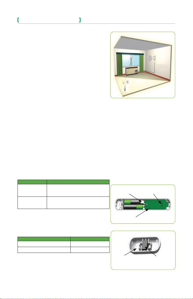
Self Testing
For best practice, the configuration of the wireless switch and magnet
unit should be configured as shown. Use the mounting template at the
end of this document for easy installation. Other configurations can be
used, such
as placing the devices on the top of the door, placed horizontally.
However, it is very important to self test the wireless switch to ensure
that it is working properly.
Location
• Never install switch unit on moving part (door or window).
• Install only magnet unit on moving part (door or window).
• Never install in direct sun.
• Ensure that the minimum distance between any SchneiderElectric wireless node and any WiFi devices (wireless routers,
wireless adapters, lap-tops using wireless networks, etc.) is at
least 3 feet (1 M) and preferably 10 feet (3 M) or more. (Fig. 3).
Notes
Electronic controls are static sensitive devices. Discharge yourself
properly before manipulating and installing the device.
A short circuit or wrong wiring may permanently damage the Terminal
Equipment Controller or the equipment.
All SED-WIN & SED-DOR series controls are designed for use as
operating controls only and are not safety devices. These instruments
have undergone rigorous tests and verification prior to shipping to
ensure proper and reliable operation in the field. Whenever a control
failure could lead to personal injury and or loss of property, it becomes
the responsibility of the user, installer, electrical system designer
to incorporate safety devices (such as relays, flow switch, thermal
protections, etc), or an alarm system to protect the entire system
against such catastrophic failures. Tampering with the devices or
unintended application of the devices will result in a void of warranty.
Please see the specifications page for operating and storage
conditions. Note that any occurring condensation can damage the
wireless switch.
Please respect polarity when replacing batteries, reversing the polarity
of the batteries can damage the wireless switch.
SED-WIN/SED-DOR
Figure -1 Opening the C over
Figure-2 Installing Switch and Magnet Bases
Figure -3 Minimum D istance fro m WiFi Device s
Viconics Technologies Inc. | 9245 Lange lier Blvd. | St.-Leona rd | Quebec | Canada | H1P 3K9 | Tel: (514) 321-5660 | Fax: (514) 321-4150
028-0415-01 www.viconics.com | sales@viconics.com November 2014
© 2014 Viconic s Technologies Inc. All rig hts rese rved.
Page 3
Wireless Door/Window Switch
The SED-WIN & SED-DOR series ZigBee Pro™ wireless switches are
used with the wireless versions of VT8000/VT7000 Series Terminal
Equipment Controllers.
A typical hospitality application is where the VT8000 wall terminal equipment controller has an on-board PIR sensor and wireless switches are
used to monitor the opening and closing of doors and windows.
Wireless door switches used with the local VT8000 PIR cover provide
advanced local occupancy routines allowing for increased energy savings during occupied hours without sacrificing occupant comfort.
Wireless window switches are used to monitor outside windows and or
patio and balcony doors being opened or closed. This allows prevention
of unnecessary energy consumption by the tenants.
Typical applications of VT8000/7000 Series Room Controllers with SEDWIN & SED-DOR series Zigbee Pro™ wireless switches can be used in
network ready mode with or without integration to a central management
system to allow for advanced functions such as central reservation occupancy functions.
A combination of up to twenty SED-WIN & SED-DOR door and/or window switches can be used simultaneously with a single VT8000 Series
Terminal Equipment Controller.
The SED-WIN & SED-DOR switches are factory delivered with 2 AAA
batteries and can be installed, configured, and used right out of the
box. Due to extremely small current consumption of the switches, the
expected battery life is approximately 10 years and is equivalent to the
battery shelf-life.
No tools are required for commissioning or servicing the door switch. A
very simple interface with an on-board LED and hidden switch provides
the required functions for local interaction. Local information for battery
life and connectivity (heartbeat) are provided at the VT8000/7000 Series
Terminal Equipment Controller local display level, or through the Zigbee
Pro™ wireless network.
Each switch is also factory supplied with a magnet, locking security
tamper proof screw, and self tapping mounting screws for installation.
SED-WIN/SED-DOR
Model Chart
PART NUMBER DESCRIPTION
SED-WIN
SED-DOR
SED-WIN
SED-DOR
To verify if the device is a wireless window switch or wireless door
switch:
Power cycle the switch (remove the battery for 60 seconds and then
insert again) and verify the LED blinking pattern to confirm if it is a
window switch or door switch; or simply read the label located on the
electronic board.
Wireless Win dow Switch (Patio and balcony
doors) Complete with magnet, batteries,
and required mounting hardware.
Wireless Door Switch
Complete with magnet, batteries,
and required mounting hardware.
Part Number Number of Blinks
Window Switch (SED-WIN & SED-DOR) 2 blinks
Door Switch (SED-WIN & SED-DOR) 3 blinks
WARNING: Respect polarity when replacing batteries or the switch may
be damaged. The (+) and (–) terminals are indicated on the board.
NOTE: The magnet is located on opposite side of security screw.
(Opposite side of the batteries)
Viconics Technologies Inc. | 9245 Lange lier Blvd. | St.-Leona rd | Quebec | Canada | H1P 3K9 | Tel: (514) 321-5660 | Fax: (514) 321-4150
028-0415-01 www.viconics.com | sales@viconics.com November 2014
Pull Tab
(remove to power
up
switch)
Hidden
Figure-4 Wireless Switch Components
Housing
Figure-5 Magnet Components and Proper Magnet
Orientation
Switch
LED
(switch side)
Magnet
3
© 2014 Viconic s Technologies Inc. All rig hts rese rved.
Page 4
4
Wireless Door/Window Switch
SED-WIN/SED-DOR
Pairing Process Procedure
NOTE: See VTR/VT installation manual for details on PAN ID parameter.
PAN ID for Centralized Networked Applications with MPM:
VT8000 Series VT7000 Series
1 - 500 1 - 250
PAN ID for Stand-alone Applications with no MPM:
VT8000 Series VT7000 Series
501 - 1000 N/A
Spec ial no te for all VT 700 0 Room Co ntrolle rs: The VT700 0 Room Controllers ar e only
compatible within a SmartStruxure network with MPM Controllers
Configuring Actions
Short Switch Duration Result
Approx. 1 second Enter Pai ring Mo de (page 8)
Approx. 1 s econd ( afte r being p aired ) Displ ays MAC add ress ( page 8 )
4+ seco nds and l ess tha n 10 second s Batter y Status (pag e 13 )
10+ seco nds and l ess tha n 20 seconds Diagnostic Mode (page 12)
20+ seconds Resets S witch
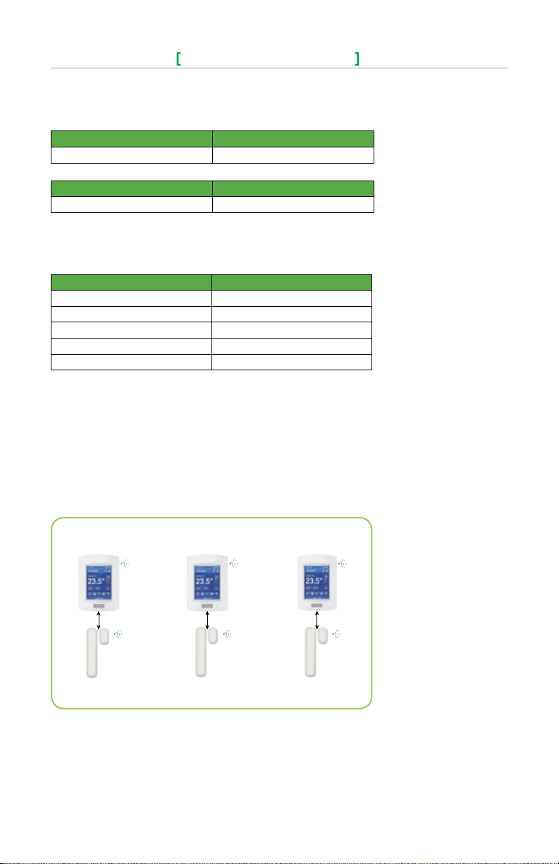
Using VT8000 Controllers for Stand-alone Systems
When PAN ID is used with Range of 501 - 1000 for Stand-Alone Systems
In this application, the VT8000 controller(s) are the coordinators to their own systems and are
network masters for each wireless switch reporting to them. A unique network is needed for proper
functionality according to the following:
• Wireless controller factory default Channel and PAN ID = controller(s) offline.
• Each VT8000 controller is its own network coordinator.
• Range of PAN ID on all controllers to use is 501 - 1000. This range is reserved for stand-alone
system operation.
Coordinator
VT8000 Series Controller
Channel: 15 PAN ID: 501
Coordinator
VT8000 Series Controller
Channel: 15 PAN ID: 502
Coordinator
VT8000 Series Controller
Channel: 15 PAN ID: 503
Window or Door Switch Window or Door Switch Window or Door Switch
Figure -6 Stand- alone VT8 000 serie s systems
Notes:
• Each VT8000 Controller uses a unique PAN ID and/or Channel settings.
• If all available PAN ID’s are used (501-1000), use a different channel.
• Up to 20 switches can be linked to each VT8000 Controller.
• The MAC address is only used to confirm parent pairing.
Viconics Technologies Inc. | 9245 Lange lier Blvd. | St.-Leona rd | Quebec | Canada | H1P 3K9 | Tel: (514) 321-5660 | Fax: (514) 321-4150
028-0415-01 www.viconics.com | sales@viconics.com November 2014
© 2014 Viconic s Technologies Inc. All rig hts rese rved.
Page 5

Wireless Door/Window Switch
SED-WIN/SED-DOR
Typical floor plan of a unique network for Stand-Alone systems with VT8000 Controllers:
5
Figure-8 Typical Stand-alone floorplan
Viconics Technologies Inc. | 9245 Lange lier Blvd. | St.-Leona rd | Quebec | Canada | H1P 3K9 | Tel: (514) 321-5660 | Fax: (514) 321-4150
028-0415-01 www.viconics.com | sales@viconics.com November 2014
© 2014 Viconic s Technologies Inc. All rig hts rese rved.
Page 6

6
PAN ID used with a Range of 1 to 500 for Networked Systems
In this application, any controller(s) are routers to the system. The MPM is the coordinator to the
system as the MPM is the network master for any controller(s) reporting to them.
• Wireless controller factory default Channel and PAN ID = controller(s) offline.
• MPM is network coordinator.
• VT8000/7000 controllers act as a router.
• Range of PAN ID on all controllers use 1 - 500. Reserved for networked system operation.
Wireless Door/Window Switch
SED-WIN/SED-DOR
Notes:
• Each controller uses same PAN ID and Channel as MPM coordinator.
• MPM supports network integration for required GUI/System/Status objects.
• Up to 20 switches can be linked to each VT8000/7000 Controller.
Coordinator Channel, 15 PAN ID: 250
VT8000 Controller
Channel, 15 PAN ID: 250
Window or Door Switch
Figure -9 MPM and V T8000 Ne tworked Syste m
VT8000 Controller
Channel, 15 PAN ID: 250
Window or Door Switch
VT8000 Controller
Channel, 15 PAN ID: 250
Window or Door Switch
Viconics Technologies Inc. | 9245 Lange lier Blvd. | St.-Leona rd | Quebec | Canada | H1P 3K9 | Tel: (514) 321-5660 | Fax: (514) 321-4150
028-0415-01 www.viconics.com | sales@viconics.com November 2014
© 2014 Viconic s Technologies Inc. All rig hts rese rved.
Page 7

Wireless Door/Window Switch
SED-WIN/SED-DOR
Important: Device Pairing Order
If a VT8000 controller that already has a SED-WIN & SED-DOR wireless switch paired with it is then
paired with an MPM, the paired wireless switch will fail to function normally.
To avoid this problem, always pair all VT8000 controllers to be used in a networked environment
with the appropriate MPMs before you pair them with SED-WIN & SED-DOR wireless switches.
As long as the sensors are paired with the controllers after the controllers are paired with the MPMs, the
switches will function normally. Only if the controllers are paired with the switches before they are paired
with the MPMs will the switches fail to function normally.
Before Starting Pairing Procedure
Verify that the following parameters on the VT8000 controller are set correctly to avoid failure in associating the wireless switch to the controller. For more information on the list of parameters, refer to the
VT8000 controller installation manual.
This pa ramete r will only appe ar when a wirele ss net work
adapter i s prese nt. If the Termi nal Equipment C ontrol ler
is insta lled as a s tand-a lone unit or with a BACnet™ or
PAN ID
Personal Area Network
Identification
Default value = 0
Range: 0 -1000
Channel
Channel selection
Default value = 10
Range: 11 - 25
Echelon™ adapter, this pa ramete r will not b e used or
displayed.
The default val ue of 0 is not a va lid PAN ID.
The valid range o f availa ble PAN ID is fr om 1 to 1000.
Range 1 to 500 is for central ized net worked a pplic ations using
a MPM with the wirel ess sta t drive r.
Range 501 to 1000 is for st and-al one app lications where no
MPM with the wirel ess sta t drive r is used.
This pa ramete r will only appe ar when a wirele ss net work
adapter i s prese nt. If the Termi nal Equipment C ontrol ler
is insta lled as a s tand-a lone unit or with a BACnet™ or
Echelon™ adapter, this pa ramete r will not b e used or
displayed.
Schneider Electric recommends using only channels 15 and
25 o nl y.
The default val ue of 10 is not a val id chan nel. The valid ra nge
of availa ble cha nnel is f rom 11 to 25.
7
Viconics Technologies Inc. | 9245 Lange lier Blvd. | St.-Leona rd | Quebec | Canada | H1P 3K9 | Tel: (514) 321-5660 | Fax: (514) 321-4150
028-0415-01 www.viconics.com | sales@viconics.com November 2014
© 2014 Viconic s Technologies Inc. All rig hts rese rved.
Page 8

8
Wireless Door/Window Switch
Pairing - Associating Switches with Controllers
1. Remove the pull tab from the battery holder to power-up the
switch.
2. Verify or set configuration parameter “BI1” or “BI2” to “None”.
This sequence will erase the current associated devices.
3. Set the configuration parameter “BI1” to “Window” and “BI2” to
“DoorDry” as required.
4. To reset a wireless switch to its factory default settings if
previously associated, simply short the switch (use a metal tool
like a ball-point pen)and hold for 20+ seconds. 5 short blinks
will confirm reset (see Figure-10).
5. Short the switch once for less than 3 seconds and bring the
switch to the left of the controller where the COM module is
located. Hold the switch as close as possible to the controller
during the pairing process (see Figure-11).
6. The LED will display one long blink followed by one short blink
to indicate switch is in pairing mode.
7. The LED will now display 2 short blinks in succession. Make
sure to place the switch close to the COM module of the
controller.
8. The LED will display five short blinks to indicate the switch is
paired.
9. Quickly short the switch and the LED will display a blinking pattern which matches the corresponding MAC address:
Example: MAC = 43 if the LED shows 4 short blinks followed
by a pause and another 3 short blinks.
Multiple Switch Configuration
In a multiple switch configuration, up to 20 switches can be linked to
one controller. Repeat steps 5 to 9 in the pairing process procedure to
add multiple wireless switches.
When a multiple switch configuration is modified, (removing a switch),
a reset is required. Please follow these steps to perform a reset:
1. To reset the wireless switch to its factory default settings, simply
short the switch (use a metal tool like a ball-point pen) and hold
for 20+ seconds. 5 short blinks will confirm the reset.
2. Set the configuration parameter “BI1” or “BI2” to “None” and
then back to “BI1” or “BI2” to erase the removed wireless
switch.
Upgrading from a Stand-alone System to a
Networked System
When upgrading from a stand-alone system to a networked system,
it is necessary to reset any already paired switches or they will
not function, as described on page 7. The general procedure for
all switches and controllers that will be included in the networked
installation should be as follows:
1. Reset all affected paired switches to factory default settings by
shorting the switches (use a metal tool like a ball-point pen) and
holding for 20+ seconds. Five short blinks will confirm the reset.
2. Set the configuration parameter “BI1” or “BI2” to “None” and
then back to “BI1” or “BI2” to erase the removed wireless
switches on every affected controller.
3. Pair the controllers to the MPM(s) of the networked system.
4. Once all the controllers are networked, repeat steps 5 - 9 of the
pairing process procedure for each switch that will be part of
the networked installation.
SED-WIN/SED-DOR
Figure 1 0 Shorting t he Switch
Figure 11 Switch/Controller proximity during Pairing
Viconics Technologies Inc. | 9245 Lange lier Blvd. | St.-Leona rd | Quebec | Canada | H1P 3K9 | Tel: (514) 321-5660 | Fax: (514) 321-4150
028-0415-01 www.viconics.com | sales@viconics.com November 2014
© 2014 Viconic s Technologies Inc. All rig hts rese rved.
Page 9

Wireless Door/Window Switch
SED-WIN/SED-DOR
Troubleshooting Guide
NOTE: If the wireless switch has not yet been paired, restart the pairing procedure.
Condition Possible Cause Solution
The wireless s witch is n ot
activating
Batter ies not i nstalled
properly
Properly install the batteries by respecting polarity
9
The swi tch does n ot
function properly
Always display ing
“Low Bat tery”
The wireless s witch is n ot
pairing with the controller
Not installed correctly
A switch wa s remove d See Multiple Switch Configuration
Configuration parameters
need to be r eset
The wireless s witch ne eds
to be reset
Incorrect PAN ID or Channel Set to a pprop riate PAN ID or C hanne l
See pag e 2 and the mo unting template a t
the end of this docu ment
Set confi gurati on para meters “ BI1” and “BI2” to “None”
and then reset “B I1” to “Window” a nd/or “BI2” to DoorDr y
Shor t the switc h for 20+ s econd s and res tart t he pair ing
Status and Monitoring
• Once the switch is commissioned, it can be monitored by the status LED when diagnostic
mode is enabled. Once diagnostic mode is enabled, when the magnet is placed near the
switch, the LED will be off and when the magnet is away from the switch, the LED will be
on.
• The switch status can also be viewed as a present value on the network front end.
• To enter/enable diagnostic mode
Short Switch Duration Duration of Diagnostic Mode
10+ seco nds and l ess tha n 20 seconds 2 minutes
Alarms
• If a low bat tery alarm is d etected, i t will au tomatic ally be d isplayed at the end of the wal l
controller scrolling status display.
• When an a larm m essag e is disp layed, th e backlit screen on the co ntroll er will i lluminate at
the same time as th e messa ge and sh ut off d uring the rest of th e status d isplay.
Indicates that a n attac hed wireless s witchi ng devices (door or window
contac t) has a low batter y cond ition.
Low Batt
Important: It is recommended that the batteries of all switches paired with a single controller be
replaced when this alarm is displayed.
Only functional when used with a wireless communication adapter.
OR
A switch was removed (see Multiple Switch Configuration)
Viconics Technologies Inc. | 9245 Lange lier Blvd. | St.-Leona rd | Quebec | Canada | H1P 3K9 | Tel: (514) 321-5660 | Fax: (514) 321-4150
028-0415-01 www.viconics.com | sales@viconics.com November 2014
© 2014 Viconic s Technologies Inc. All rig hts rese rved.
Page 10

10
Wireless Door/Window Switch
SED-WIN/SED-DOR
Battery Status
To verify the battery strength of the wireless switch, simply short the switch for more than 4
seconds and less than 10 seconds and a blinking pattern will be displayed. After the blinking
pattern is displayed, the switch will enter diagnostic mode for a duration of 10 seconds (see Status
and Monitoring).
Number of Blinks Indication
1 blink Replace batteries
2 blinks Replace batteries soon
3 blinks Battery strength is fair
4 blinks Battery strength is good
5 blinks Battery strength is excellent
**Important: Please respect polarity when replacing batteries, reversing the polarity of the batteries
can damage the wireless switch.
Specifications
Power requirements 3.0 VDC 2 x A AA bat terie s. Factor y supp lied
Operating conditions
Storage conditions
Agency a pprova ls for all m odels CE: RT TE 1999/ 5/EC
Agency a pprova ls for wir eless models FCC comp liant to : Part 15, Sub part C
THIS DE VICE CO MPLIES WI TH INDU STRY CANA DA LICENC E-EXE MPT RSS STANDA RD( S).
OPERATION I S SUBJECT TO THE FOLLOW ING TWO CONDITIONS : (1) THIS DE VICE MAY
NOT CAUSE INT ERFERE NCE, AND ( 2) THI S DEVICE MUST ACCE PT ANY IN TERFER ENCE,
INCLUDI NG INTERFERENC E THAT MAY CAUSE UNDES IRED OPER ATION OF TH E DEVI CE.
NOTE: TH E MANUFACTU RER IS NOT RESPONSI BLE FOR A NY RAD IO OR TV
INTERF ERENCE CAU SED BY UNAU THORIZED MODIFICATIONS TO THI S EQUIPM ENT.
SUCH MOD IFICATIONS C OULD VOID THE USER’S AUTHOR ITY TO OP ERATE THE
EQUIPMENT
0 °C - 50 °C ( 32 °F to 122 °F )
0% - 95% R.H. non-condensing
-30 °C - 65 °C ( -22 °F to 122 °F )
0% - 95% R.H. non-condensing
Check with your local government for instruction on disposal of this product
All SED-WIN & SED-DOR SERIES DEvIcES ARE fOR uSE AS
OpERAtINg cONtROlS ONly AND ARE NOt SAfEty DEvIcES. thESE
INStRumENtS hAvE uNDERgONE RIgOROuS tEStS AND vERIfIcAtIONS
pRIOR tO ShIpmENt tO ENSuRE pROpER AND RElIAblE OpERAtION IN
thE fIElD. WhENEvER A cONtROl fAIluRE cOulD lEAD tO pERSONAl
INjuRy AND OR lOSS Of pROpERty, It bEcOmES thE RESpONSIbIlIty
Of thE uSER, INStAllER, AND / OR ElEctRIcAl SyStEm DESIgNER tO
INcORpORAtE SAfEty DEvIcES (Such AS RElAyS, flOW SWItchES,
thERmAl pROtEctIONS, Etc) AND / OR AlARm SyStEmS tO pROtEct
thE ENtIRE SyStEm AgAINSt Such cAtAStROphIc fAIluRES. tAmpERINg
WIth thE DEvIcES OR mISApplIcAtION Of thE DEvIcES WIll vOID thE
WARRANty.
Viconics Technologies Inc. | 9245 Lange lier Blvd. | St.-Leona rd | Quebec | Canada | H1P 3K9 | Tel: (514) 321-5660 | Fax: (514) 321-4150
028-0415-01 www.viconics.com | sales@viconics.com November 2014
© 2014 Viconic s Technologies Inc. All rig hts rese rved.
Page 11

Wireless Door/Window Switch
SED-WIN/SED-DOR
Drawing and Dimensions
Figure-11 Switch and Switch Base Dimensions
11
Figure-12 Magnet and Magnet Base Dimensions
Viconics Technologies Inc. | 9245 Lange lier Blvd. | St.-Leona rd | Quebec | Canada | H1P 3K9 | Tel: (514) 321-5660 | Fax: (514) 321-4150
028-0415-01 www.viconics.com | sales@viconics.com November 2014
© 2014 Viconic s Technologies Inc. All rig hts rese rved.
Page 12

12
Wireless Door/Window Switch
Marking Templates for Mounting
SED-WIN/SED-DOR
Location of Security Screws
Viconics Technologies Inc. | 9245 Lange lier Blvd. | St.-Leona rd | Quebec | Canada | H1P 3K9 | Tel: (514) 321-5660 | Fax: (514) 321-4150
028-0415-01 www.viconics.com | sales@viconics.com November 2014
© 2014 Viconic s Technologies Inc. All rig hts rese rved.
 Loading...