

Page 1
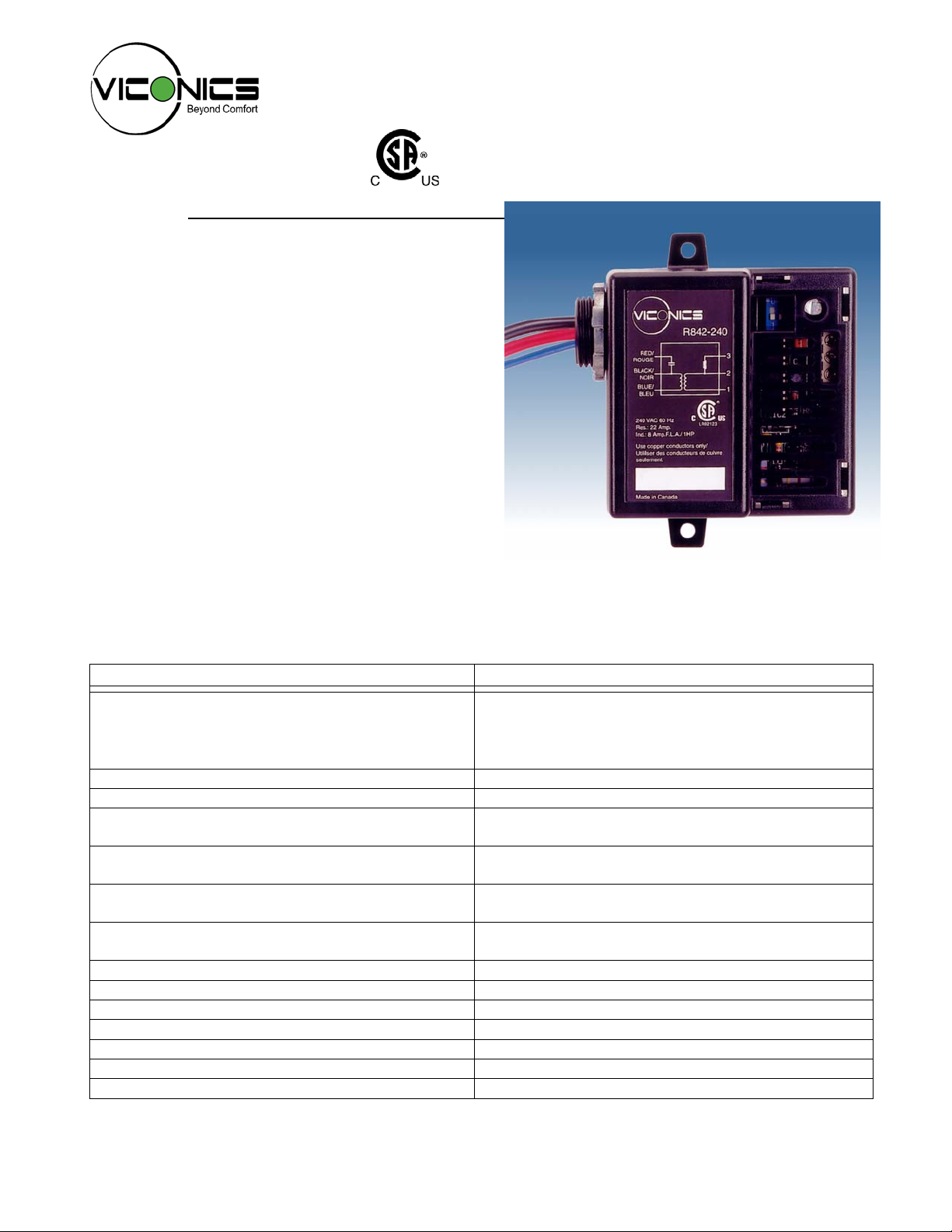
R842 Electronic Relay For Electric Baseboards
Description
Viconics’ innovative R842 electronic relay has been
designed for silent control of high voltage resistive
heater loads (120V to 600 Vac) from a low voltage
control circuit. Typical applications include control of
electric baseboard and cabinet heaters in commercial
buildings. Inductive motor loads can also be controlled
(120 and 240 Vac models only).
Using advanced microprocessor-based circuitry, the
R842 is capable of handling greater than 500,000 cycles
(typical). It has a built-in transformer and is compatible
with most industry standard electromechanical or
electronic thermostats with on/off outputs. A unique
feature of product is that it can operate with a value
priced Viconics’ T186 electronic PI (proportional and
integral) room thermostat with setpoint capability,
providing exceptional accuracy, comfort, and energy
savings.
Features Benefits
• Built-in transformer
• Universal replacement part
• Compatible with electronic T186 room sensor
Fig.1 - R842 relay for electric baseboards
⇒ Permits fully electronic PI control
• Unique compatibility with Viconics’ own designer
electronic thermostat
⇒ Improved accuracy (+/-0.3ºC) and comfort
⇒ Energy savings
⇒ Aesthetically pleasing thermostat
• Reliable microprocessor-based design ⇒ Long life
• Compatible with all standard 24 V thermostats ⇒ Adds flexibility
• Constant 10 second time delay
• Built-in transformer
• Broad voltage ranges available: 120, 208, 240,
⇒ Not affected by ambient temperatures typically
found in older, thermal type baseboard relays
⇒ Less inventory to stock
⇒ Easier installation
⇒ Covers most voltage applications
277, 347, 600 Vac.
• Status LED
⇒ Confirms operation
⇒ Simplifies troubleshooting
• Silent operation ⇒ Will not disturb occupants
• Direct replacement of competitive models ⇒ Easy to retrofit
• Large resistive amperage load rating ⇒ Will handle the largest baseboards with ease
• Inductive ratings ⇒ Used to control motor loads (fans, pumps, etc)
• Compact enclosure ⇒ Fits inside baseboard
• Standard ½” male conduit bushing ⇒ Can be installed on most electrical junction boxes
• 2 year warranty ⇒ Assured dependability
1
Page 2
Description (Cont’d)
(
)
The R842 has several advantages over traditional
electromechanical baseboard relays. The latter use
the principle of thermal expansion to make or break
the high voltage circuit. This operation typically takes
45 seconds and adds inaccuracy to the temperature
control loop. The R842, with enhanced electronic
circuitry, substantially reduces this long time delay
and is not affected by ambient temperature
conditions.
Due to its compact design, the R842 easily fits into
most electric baseboard enclosures and can replace
most competitive models. For junction box mounting,
a standard ½” male screwed fitting is available. In
addition, a high intensity LED is provided to indicate
operation and simplify troubleshooting. Silent
operation will ensure that each installation is trouble
free.
R842 Relay Models
Model No.
R842-120
R842-208
R842-240
R842-277
R842-347
R842-600
Voltage
Vac)
120 22
208 22
240 22
277 19
347 18
600 10
Amperage
(A
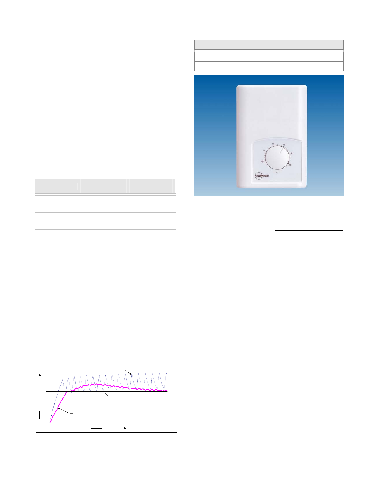
T186 Electronic PI Thermostat
The microprocessor-based design of the R842
permits the use of T186 electronic room sensor with
setpoint as an alternative to electromechanical
thermostats. The T186 transmits the actual
temperature and setpoint to the R842. The resulting
solid state PI control loop is much more accurate
than that offered by conventional thermostats and
eliminates wasted energy caused by on/off cycling
with these types of thermostats (see Fig. 2).
The T186 can also be used as lower cost alternative
to the use of solid state relays and pulse width
modulated thermostats, sometimes used to control
electric heat baseboards.
Electromechanical thermostat
Temperature
T186 PI control
Setpoint (comfort temperature)
Fig.2 - On/Off mechanical control vs PI electronic control
Time
T186 Sensor Models
Model No. Scale Range
T186C-01
T186F-01
5 °C to 30 °C
40 °F to 90 °F
Fig.3 - T186 electronic PI room sensor with setpoint
Typical Guide Specification
The relay shall be a microcomputer-based with PI, time
proportioning control capability. It should have an
average life of greater than 500,000 cycles and include
a built-in transformer. Relays shall be compatible with
all of the following control signals: Viconics T186
electronic room sensor with setpoint permitting PI
control with an accuracy of +/-0.3ºC and standard 24
Vac thermostats. Relay shall have a constant 10 second
time delay and shall not be affected by ambient
temperatures. The relays shall be equipped with a
status LED to confirm operation. Required quality: R842
electronic baseboard relay from Viconics.
2
Page 3

Installation
p
r
Important: All wiring must conform to local and
national electrical code regulations. Please read
these instructions carefully before the installation.
Failure to follow the instructions could damage the
product or cause a hazardous condition. Installation
must only be performed by a qualified service
technician. Disconnect power supply before installing
in order to prevent electrical shock. There are two
basic methods to install the R842 baseboard relay.
A. Installation Inside Electric Baseboard
Electric baseboard strip
Fig.4 - R842 relay installation Fig.5 - R842 relay, installation in an electrical junction box
1. Use the plastic mounting tabs to secure the unit
to the inside of the electrical enclosure.
2. Secure to the cabinet with screws.
3. Cut one or both plastic mounting tabs if space is
needed inside the enclosure.
4. If a high voltage separation barrier is needed,
please contact the baseboard manufacturer.
5. Do not exceed the maximum rated temperature
of the R842 unit. (65°C/149°F)
Secure inside cabinet
using mounting screws
B. Junction Box Installation
Use the supplied lock nut to secure the relay to the
electrical junction box. It is possible to mount the relay
completely inside the junction box or outside, as
desired. In the case of the former, make sure that the
front of the R842 relay is facing the cover of the junction
box. For mounting outside of the junction box, make
sure that the front of the relay is visible. In both cases,
this will permit the installer to view the red LED in order
to confirm operation.
From other high voltage
junction boxes
Standard 4 "x 4" junction box
installed in the ceiling
Electric baseboard strip
Dip Switch Settings
High voltage
wires
24 Vac Low voltage
control wires
To other high voltage
juction boxes
T186 sensor
Whenever using one R842 relay, please set the dip
switches as follows, depending on the input signal:
1. Two wire low voltage electromechanical thermostat:
set both switches to "ON"
2. Viconics' T186 set both switches to "OFF"
For all applications involving multiple R842 relays,
please refer to the diagrams on pages 4, 5, and 6
24 Vac Low voltage
control wires to
thermo st a t
ON
2
1
ON
1
If a high voltage separation barrier is needed,
lease contact baseboard manufacture
Fig.6 - R842 relay, installation inside baseboard cabinet Fig.7 - R842 relay, location of dip switches
Refer to wiring diagrams for dip switch setting
per application.
2
3
Page 4

A
A
A
A
Typical applications & wiring
Two wire low voltage thermostat using R842 baseboard
relay internal transformer
Baseboard(s) / load(s)
Relay(s)
Thermostat(s)
Transformer
One
One
One
Internal
RED
BLACK
BLUE
1
Internal circuit
ON
2
1
2 wire low voltage
thermostat
3
2
1
3
Load side
L1
L2 / N
Junction box
Set both switch on relay
to factory default ON position
2
Two wire low voltage thermostat using R842 baseboard
relay internal transformer for multiple relay
arrangement
Baseboard(s) / load(s)
Relay(s)
Thermostat(s)
Transformer
Load side
Load side
Load side
L1
L2 / N
RED
BLACK
BLUE
RED
BLACK
BLUE
1
RED
BLACK
BLUE
1
Maximum of 10 slave units
Internal circuit
ON
12
Internal circuit
ON
12
Internal circuit
ON
12
Multiple
Multiple
One
Internal
2 wire low
voltage thermostat
3
2
1
3
3
2
1
3
3
2
1
3
djust thermostat
anticipator to 0.1 A
or less.
Set both switch
on master relay
to factory default
position
ON
Master
Slave(s)
Set switch on
all slave relays to
S1 =
&
ON
S2 =
OFF.
djust thermostat
anticipator to 0.1 A
Two wire low voltage thermostat using a separate
24 Vac transformer
Baseboard(s) / load(s)
Relay(s)
Thermostat(s)
Transformer
One
One
One
External
2 wire low voltage
thermostat
Load side
Junction box
RED
BLACK
BLUE
1
L1
L2 / N
Internal circuit
ON
12
2
3
2
1
Set both switch on relay
to factory default ON position
Separate remote
3
24 Vac transformer
Two wire low voltage thermostat using a separate
24 Vac transformer for multiple relay arrangement
Baseboard(s) / load(s)
Relay(s)
Thermostat(s)
Transformer
2
4
L1
L2 / N
Internal circuit
RED
Load side
Load side
Load side
BLACK
BLUE
RED
BLACK
BLUE
RED
BLACK
BLUE
Internal circuit
Internal circuit
ON
2
1
ON
12
ON
12
Multiple
Multiple
One
External
2 wire low
voltage thermostat
3
2
1
3
2
1
3
2
1
djust thermostat
anticipator to 0.1 A
or less.
Separate remote
24 Vac transformer
L1
L2 / N
Set both switch on master
relay to factory default
position
ON
Set switch on
all slave relays to
S1 = ON &
S2 =
OFF.
djust thermostat
anticipator to 0.1 A
or less.
L1
L2 / N
Master
Slave(s)
1 High voltage blue wire is always connected. R842 units are powered devices.
2 Provide overload protection and disconnect as required.
3 Do not use 24 Vac terminal #1 as power supply to an electronic thermostat. Use a separate transformer.
4 L1, L2 & L3 can be mixed / matched.
5 Operates only if all relays control the same phase of a 3 phase system or on a single phase branch.
4
Page 5

A
Multiple two wire low voltage thermostats using the
same separate 24 Vac transformer to control
multiple R842 baseboard relays
Baseboard(s) / load(s)
Relay(s)
Thermostat(s)
Transformer
L1
L2 / N
Internal circuit
RED
Load side
Load side
Load side
BLACK
BLUE
RED
BLACK
BLUE
RED
BLACK
BLUE
Internal circuit
Internal circuit
ON
12
ON
12
ON
12
Multiple
Multiple
Multiple
External
2 wire low
voltage thermostats
3
2
1
3
2
1
3
2
1
L1
L2 / N
Separate remote
24 Vac
transformer
Set both switch
on all relays
to factory default
position
ON
Baseboard(s) / load(s)
Relay(s)
T186 thermostat
Load side
Junction box
Viconics T186 sensor to control
one R842 baseboard relay
One
One
One
sensor
T186
2 wire non polarized
Internal circuit
RED
BLACK
BLUE
L1
L2 / N
ON
1
3
2
2
1
Set both switch on relay
to
position
OFF
djust thermostat
anticipator to 0.1 A
or less.
Viconics T186 sensor for
master / slave arrangement of R842 baseboard relays
Baseboard(s) / load(s)
Electrical Specifications:
Relay(s)
T186 Thermostat
Load side
Load side
Load side
2
5
L1
L2 / N
RED
BLACK
BLUE
1
RED
BLACK
BLUE
1
RED
BLACK
BLUE
1
Maximum of 10 slave units
Internal circuit
Internal circuit
Internal circuit
1 High voltage blue wire is always connected. R842 units are powered devices.
2 Provide overload protection and disconnect as required.
3 Do not use 24 Vac terminal #1 as power supply to an electronic thermostat. Use a separate transformer.
4 L1, L2 & L3 can be mixed / matched.
5 Operates only if all relays control the same phase of a 3 phase system or on a single phase branch.
ON
12
ON
1
ON
12
2
Multiple
Multiple
One
2 wire non polarized
3
2
1
3
3
2
1
3
3
2
1
3
sensor
T186
Set both switch
on master relay
to
Set both switch
on slave relays
to factory default
ON
Install a jumper
across terminals
1 and 3 on all
slave relays
Note: Slave units life cycle is
100,000 cycles
position
OFF
Master
Slave(s)
position
Model Volt
Resistive
Rating (A)
Inductive
Rating (HP)
R842-120 120 22
R842-208 208 22
R842-240 240 22
½ HP
8 Amp
1 HP
8.8 Amp
1 HP
8 Amp
R842-277 277 19 N/A
R842-347 347 18 N/A
R842-600 600 10 N/A
5
Page 6

]
Specifications
Physical Specifications:
Ambient Operating
Temperature and Humidity Limits
• -20°C to 65°C (-4°F to 149°F )
• 0 % to 95 % R.H. non-condensing
Ambient Storage
Temperature and Humidity Limits
• -40°C to 80°C ( -40°F to 176°F )
• 0 % to 95 % R.H. non-condensing
• Greater than 500,000 (typical, resistive loads)
Life cycles
• 100,000 (typical, inductive loads for models
R842-120, R842-208 and R842-240 only)
Internal R842 transformer rating
Wire length
Net weight
Recommended wire size for screw terminal
Agency approval
• 24 Vac, -15%, +10% 50/60 Hz;
• 2.4 VA Class 2 transformer
• 8 inches [20 cm]
• 0.51 Lbs / 0.23 Kg
• 18-22 gauge
CSAus File no. LR92123 as per CSA Standard
• c
C22.2 no 24
Dimensions:
0.40" [10 mm]
3.70" [94 mm]
2.90" [74 mm]
0.40" [10 mm]
1.93" [49 mm]
0.90" [23 mm]
0.30" [8 mm]
Ø0.16" [4 mm]
1.77" [45 mm]
0.82" [21 mm]
1.65" [42 mm] 1.20" [30 mm]
0.39" [10 mm]
2.85" [72 mm]0.35" [9 mm]
1.60" [41 mm]
0.39" [10 mm]
0.12" [3 mm]
NOTE: VICONICS RESERVES THE RIGHT TO MAKE MODIFICATIONS WITHOUT PRIOR NOTICE.
All R842 series controls are for use as operating controls only and are not safety devices. These instruments have
undergone rigorous tests and verifications prior to shipm ent to ensure proper and reliable operation in the field.
Whenever a control failure could lead to personal in jury an d/or loss of property, it becomes the res ponsi bility of th e
user / installer / electrical panel designer to incorporate safety devices ( such as relays, flow switch, thermal
protections, etc… ) and/or alarm system to protect the entire system against such catastro phic failures. Tampering
of the devices or miss application of the device will void warranty.
Viconics Electronics Inc.
9245, Langelier Blvd, St-Leonard, Quebec, Canada H1P 3K9
LIT-R842X-E04
0.65" [17 mm
0.95" [24 mm]
sales@viconics.com
www.viconics.com
6
 Loading...