

Page 1
HP727
Single speed swimming pool heat pump controller
Operation manual
TTAABBLLEE OOFF CCOONNTTEENNTTS
S
1. General Description
2. Specifications
3. Installation Instructions
4. Electrical Wiring
5. Instrument Wiring
6. Instrument Identification
7. Operation
8. Service and Calibration
9. Troubleshooting
10. Defrost Cycle Sequence
11. Temperature Sensor Chart
12. Advanced Applications
\\\\NNTTSS4400PPDDCC0022\\BBIINNDDEERRSS\\11__BBIINNDDEERR\\0088__HHPP77XXXX\\0099__HHPP772277\\HHPP772277__0033..ddoocc 44//66//004
1
1
4
Page 2

1. GENERAL DESCRIPTION
The HP727 is a powerful microcomputer control designed for use in an outdoor swimming pool heatpump. The control features 3
digit temperature display and 3 push button keys. All adjustments are performed by simple key operations. The HP727 controls the
main compressor contactor, the 3 evaporator fan speeds, and the water circulating pump. The HP727 monitors both evaporator and
water temperature using precise thermistor sensors for superior control.
The control features full diagnostics messages, simplifying both installation and service. The HP727 is an excellent alternative to
electromechanical controls offering improved water temperature control accuracy, accurate defrost control, anti-short cycle timer,
and solid-state reliability all in a single package.
The HP727 features three speeds fan motor control for optimum efficiency and minimum acoustic noise.
All calibration and user parameters are stored in an EEPROM memory. There are no trimmer potentiometer adjustments. All
adjustments including sensor calibrations are done through the front panel. The HP727 features full self-test diagnostic capability
and sensor re-calibration if needed.
The HP727 offers maximum corrosion and vibration protection. All printed circuit board interconnections are soldered. The main
PCB is dipped in silicone. This assures maximum board protection even underneath the PCB components, against humidity, air
pollutants, chlorine vapors and vibrations.
2. VICONICS HP727 SWIMMING POOL HEATPUMP CONTROL SPECIFICATIONS
OPERATING CONDITIONS:
Rated Operating Conditions: 33 °F to 120 °F; R.H. 0% to 100 %, Non-Condensing
Storage: - 40 °F to 120 °F; R.H. 0% to 100 %, Non-Condensing
PERFORMANCE:
Accuracy: ± 1.8 °F
Repeatability: ± 0.2 °F
Resolution: ± 1 digit
INPUTS:
Swimming Pool Water Return Temperature Thermistor Sensor ( 0 °F To 120 °F )
Evaporator Defrost Temperature Thermistor Sensor ( 0 °F To 120 °F )
Contact From Remote High Pressure Switch Dry Contact Input
Contact From Remote Low Pressure Switch Dry Contact Input
Contact From Main Flow Switch Dry Contact Input
Contact From Remote Spa Select Flow Switch Dry Contact Input
OUTPUTS:
Compressor Relay Output:: 1A @ 24 Vac
3 Speeds Fan Relay Outputs: 4A @ 240 Vac
Circulating Pump Relay Output: 1A @ 24 Vac
GENERAL:
• Complete Diagnostic Error Messages
• Display: 3 Digits Display 0.56" High
• LED Status Indicators: Pool mode LED, Spa mode LED and Heat on LED
• Power supply : 0 / 12 / 24 Vac center tap transformer ±10% 50\60 Hz
- 5 VA required on 12 Vac for controller only
- 100 VA maximum for 24 Vac power connection
• Dimensions: approx. 5.5" x 6.0"
• Weight: 700 gm (1.51 lb.)
• Protection Against Humidity: Unit dipped with silicone based conformal coating
• Connectors: 1/4" fast-on connectors; screw terminals for field connections
• cCSAus file # LR92123
Important note: Heatpump unit should not be operated when outdoor air temperature is near or under freezing point; or as
specified by manufacturer of heatpump.
2
2
Page 3

3. INSTALLATION INSTRUCTIONS
UNPACKING
Examine the package on reception for any signs of external damage it may have received during transit. If damage is found, notify
the carrier immediately. Notify manufacturer or their agent immediately of any deficiencies.
INSTALLATION:
Take care in handling the Printed Circuit Board ( PCB ) so as not to damage or scratch the silicone conformal coating. Damage to
this coating will affect the resistance to moisture and humidity.
Install the board to the front panel using # 6-32 screws. Push ( or remove ) the fast-on connectors at a right angle to prevent bending
the board connectors.
Align and install the lexan cover membrane to the metal door.
4. ELECTRICAL WIRING
CAUTION:
NO HIGH VOLTAGES ARE PRESENT ON THE TERMINALS OF THIS INSTRUMENT ( EXCEPT AT THE FAN RELAYS
TERMINATIONS ) PLEASE READ ALL THE INSTRUCTIONS IN THIS MANUAL CAREFULLY, AND HAVE THE WIRING
DONE BY A SKILLED PROFESSIONAL.
THE INSTRUMENT HAS UNDERGONE RIGOROUS TESTS AND VERIFICATIONS PRIOR TO SHIPMENT TO ENSURE
PROPER AND RELIABLE OPERATION IN THE FIELD. IT IS THE RESPONSIBILITY OF THE USER OR ELECTRICAL
PANEL DESIGNER TO INCORPORATE SAFETY FEATURES ( SUCH AS OVER / UNDER TEMPERATURE CUTOUT
DEVICES ) TO PROTECT THE ENTIRE SYSTEM FROM GENERAL FAILURES.
• All wiring must conform with local or national electrical code regulations.
• See fig. 2 for electrical wiring diagram
• Some wiring to the board is done using 1/4" fast-on connectors.
• The instrument should be wired before applying power !
• Power supply : 0 / 12 / 24 Vac center tap transformer ±10% 50\60 Hz
- 5 VA required on 12 Vac for controller only
- 100 VA maximum for 24 Vac power connection
• The instrument front panel needs to be splash proof, and protected against the elements.
• The HP727 electronic controller should be mounted inside the control panel is NOT waterproof. The electrical panel must
therefore be properly protected against rain, dust and excessive water vapor condensation.
3
3
Page 4
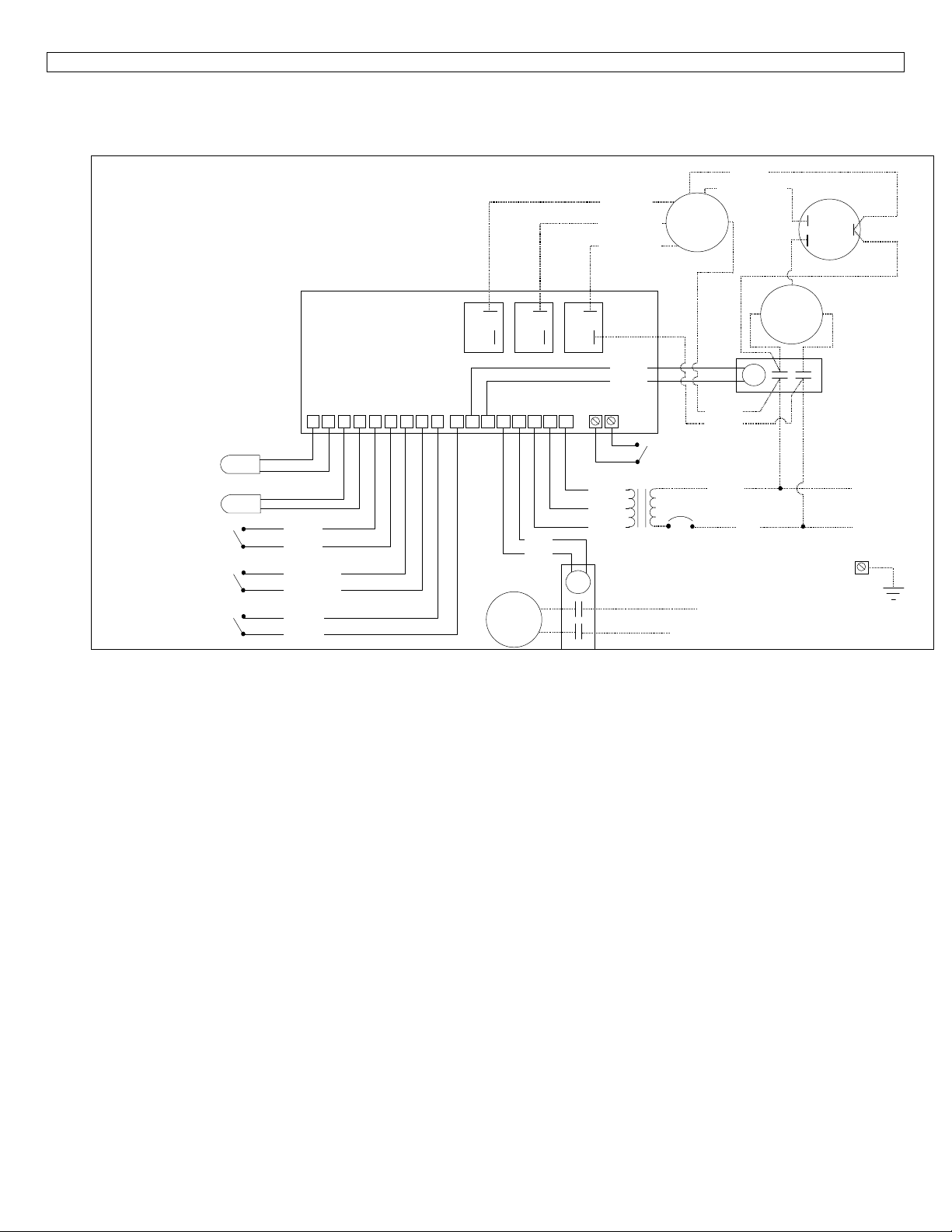
5. INSTRUMENT WIRING DIAGRAM
Wiring Diagram
Water sensor
Defrost sensor
High pressure switch
Closed = OK
Opened = high pressure
Low pressure switch
Closed = OK
Opened = low pressure
Flow switch
Closed = flow
Opened = no flow
Black
Black
Light Blue
Light Blue
Purple
Purple
HP727
Control Board
RLY1 RLY2 RLY3
12345678910 13 14 15 16 1711 12
FILTER
PUMP
Blue
Blue
Low (Red)
Med (Blue)
High (Black)
Yellow
Yellow
Remote switch
Pool (opened)
Spa (closed)
24 Vac
12 Vac
0 Vac
24 Vac transformer
24 Vac filter
pump contactor
Black & White
FAN
White
Brown
Black
Orange (240 Vac)
Red (208 Vac)
L1
L2 or Neutral
Brown
CAP
F
C
COMPRESSOR
S
R
C
24 Vac compressor
contactor
or
Ground
208 / 240 Vac
50 / 60 Hz
Herm.
L1
L2
Wiring727 .dsf
4
4
Page 5
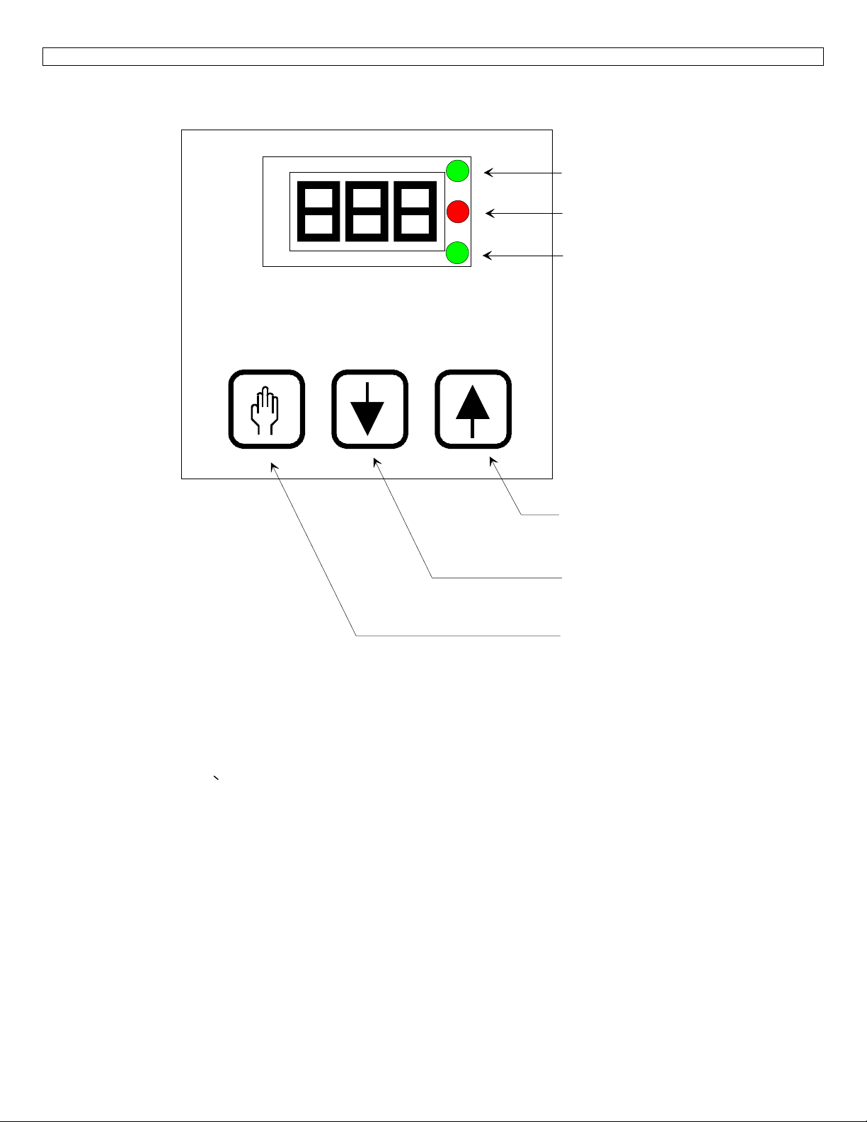
6. INSTRUMENT IDENTIFICATION
Pool LED
Heat on LED
Spa LED
Increase key
Decrease key
Service / Select key
DESCRIPTION OF FRONT PANEL:
POOL LED: Indicates that the Pool setpoint is selected.
SPA LED: Indicates that the Spa setpoint is selected.
HEAT ON LED: Indicates that the pool heater ( heatpump compressor ) is on, heating the water.
DIGITAL DISPLAY: Normally displays the actual water temperature. In set mode displays other parameters.
SERVICE / SELECT KEY: Used to enter the service mode or select between Pool and Spa temperature setpoint.
INCREASE KEY ↑ : Increases the selected parameter value.
DECREASE KEY ↓ : Decreases the selected parameter value.
NOTE: The display may be changed in steps by pushing the ↑ or ↓ keys repetitively, or automatically by holding down the same key
longer.
5
5
Page 6

7. OPERATION:
WHEN POWER IS FIRST APPLIED TO A FACTORY UNIT:
• The display will show [888] and the 3 status LED’s will come on for 4 seconds and then go off for 1 second.
• The pump will go on and then the actual water temperature will be displayed.
Factory settings of main parameters:
Pool setpoint: OFF
Spa setpoint: OFF
Filtration time FIL: 8 hours per day
The actual temperature displayed is held in memory and displayed for 5 minutes until the water temperature sensor has sampled
circulating water. After that delay of 5 minutes, the displayed temperature is automatically updated and displayed.
CONFIGURING THE UNIT J1 JUMPER
The unit can control 2 different setpoints:
The pool temperature and the Spa temperature.
2 methods can be used to switch the unit between ( Pool setpoint Mode ) or ( Spa setpoint Mode ).
How to activate either ( Pool setpoint Mode ) or ( Spa setpoint Mode )
J1 jumper not cut
J1 jumper cut A remote Spa flow switch connected on CN19 will activate ( Spa setpoint Mode ) **
** Notes:
• In this mode using the select key will authorize changing the Pool or Spa setpoint, but the actual mode is determined by the Spa
flow switch connected on CN19.
• The Pool LED or Spa LED on the display will confirm which mode is active.
Using the select key will active either mode manually ( press the ↑ or ↓ to switch between ( P_S )
ADJUSTING POOL & SPA SETPOINTS:
Setpoint ranges:
Controller configured in °F Controller configured in °C
Pool setpoint:
Spa setpoint:
• The control is shipped with setpoints at OFF in Pool and Spa mode.
• The heatpump is automatically switched OFF if a setpoint below 61 °F is selected.
• In the off mode the control will display the water temperature.
• Use the select and arrow key to enter Pool or Spa mode.
• Use the ↑ arrow to increase the setpoint above 61 °F on the selected mode.
• The pool heater ( heatpump compressor ) is automatically authorized to operate if a setpoint above 61 °F is selected.
• Adjust the setpoints to required value.
TURNING THE POOL HEATER ON ( HEATPUMP COMPRESSOR ):
When there is a demand for heat.
In Pool mode: If the actual water temperature is lower than the desired Pool setpoint temperature.
In Spa mode: If the Spa mode is manually selected ( J1 in place )
OFF → 61°F to 95°F OFF → 16°C to 35°C
OFF → 61°F to 104°F OFF → 16°C to 40°C
Or if the Spa flow switch is energized ( J1 cut )
And if the actual water temperature is lower than the desired Spa setpoint temperature.
When heatpump is energized:
• The Heat On LED is energized.
• The compressor will come on.
• The fan will come on at a speed dictated by coil temperature.
• Heat will stay on until setpoint is satisfied.
6
6
Page 7

Note that each time the compressor turns off , there will be a 3 minute anti-cycling delay before it can be turned on again.
7
7
Page 8

ADJUSTMENT OF MINIMUM FILTRATION TIME
The HP727 features an adjustable minimum filtration period. Parameter FIL.
• A daily 24 hours cycle is divided 6 daily periods of 4 hours ( 240 minutes ).
• The adjusted parameter value represent the minimum total daily hours that filtration is required.
FIL parameter adjustments:
Pump is always OFF Pump will work 2 to 23 hours daily Pump is always ON
• In OFF mode the circulating pump needs to be always on, or energized by an external timer clock.
• In ON mode, the circulating pump is always on.
The selected minimum filtration time is divided equally into the 6 daily periods.
Ex.: Selected 4 hours ÷ 6 periods = 40 minutes per period. So the circulating pump will work 40 minutes for each period of 4
hours.
The minimum selectable filtration time is 2 hours ( 6 periods of 20 minutes each )
When the circulating pump is energized, if there is a heating demand during a filtration period:
• The circulating pump will stay on until the heating demand is satisfied.
• During that period the minimum filtration time counter is still active and counting.
• If the daily minimum filtration time is obtained and the heat demand is not satisfied, the circulating pump will stay on until the
heating demand is satisfied.
• If the daily minimum filtration time is obtained and the heat is satisfied, there is still a 15 minutes circulating pump time per
period ( every 4 hours ). This is done to sample the pool water temperature is case the water needs to be heated. ( not valid if FIL
parameter = OFF )
OFF 2 hours to 23 hours ON
Whenever the FIL parameter is changed, the daily counter will reset.
BACKWASH OPERATIONS:
For backwash operation do the following:
1. Cut out power to the pump ( with line voltage switch or ( FIL = off, POL = off and SPA = off )).
2. Prepare system for backwash and energize the pump ( with line voltage switch or ( FIL = on )).
3. The circulating pump will go ON and the controller will not check for 5 minutes if water flow is present at pool flow switch.
4. You will have 5 minutes of uninterrupted water flow to do the backwash.
5. To stop the circulating pump use ( the line voltage switch or ( FIL = off )).
Normally, when the circulating pump is requested to operate, and there is no water flow detected at the flow switch, the pump will
automatically cut off. This procedure will give a 5 minutes period of uninterrupted water flow, before the circulating pump cuts off.
TO CHANGE THE DISPLAY BETWEEN °F OR °C:
Factory default is °F
• Touch and hold down the set key until the message POL appears
• Touch the [Service / Select ] key until the message F_C appear.
• Touch the ↑ arrow key to select °F or touch the ↓ arrow key to select °C
EEPROM RECOVERY:
If a flashing PLE or CSE error message appears, hold down the Service / Select key until the error message disappears ( approx. 4
seconds ). The control will be re-initiated to factory default.
Re-enter the Pool / Spa setpoints and minimum filtration time parameter.
HEATPUMP DEFROST OPERATION:
During the defrost cycle of the evaporator coil, the display will show FS to indicates that the unit is defrosting. During this time the
fan is in high speed and the compressor is inactive. See section 10. for defrost sequence.
8
8
Page 9

8. SERVICE AND CALIBRATION:
CALIBRATION AND RECONFIGURATION SHOULD BE DONE WITH CAUTION BY QUALIFIED PERSONNEL ONLY.
To enter the service mode, press down the Service key, for 8 seconds, until the display show the message Loc. You have 12
seconds from the time the last key was touched to make an adjustment. 12 seconds after the last key was depressed, any modified
value will be stored into EEPROM memory. After that, the unit will return to normal operation mode.
Adjustable parameters:
Loc
dEL
tSC
Lock code Adjustable from 00 to 99 ( 00 is no lock mode at all )
Factory default value is 50
Compressor anti-cycle delay by-pass Parameter value is at 0. Adjust value to 1 and wait
until control goes back in normal operation mode. 3
minutes anti-cycling delay is by-passed for 1 cycle
only.
Water temperature calibration ( Shows the actual water
temperature )
Adjustment is ± 5°F ( ± 3°C )
dSC
db1
Pressing the Service / Select key repetitively will scroll down all parameters.
Go to the desired parameter. The display will show the parameter name.
Use the ↑ or ↓ arrow once to display the actual value of the selected parameter.
Use the ↑ or ↓ arrow to adjust the parameter to the selected value
The display may be changed in steps by pushing the arrows briefly, or faster by holding down the desired arrow key.
NOTE: Any modified parameter value will be stored 12 seconds after the last arrow key was touched
The new value will be stored into EEPROM memory and the unit will return to normal operation mode.
Important notes:
Any time a new parameter value is stored, the display will blank out momentarily
Any modified parameter should be stored in writing on the instrument label inside the heatpump unit.
LOCK CODE ( Loc ):
The lock code provides security against unauthorized tampering of parameter values.
If the lock feature is enabled
Pressing the [Service / Select ] key for 8 seconds, will make the "Loc" message appear on the display.
Enter the Loc code value using the arrows.
Evaporator defrost temperature calibration. ( Shows the actual
evaporator temperature ) ( Viewable in calibration mode only )
Pool / Spa setpoint hysterisys 0.2°F to 2.0°F ( 0.1°C to 1.1°C )
Adjustment is ± 5°F ( ± 3°C )
Factory adjustment is 0.8°F
If an incorrect code is entered, the unit will exit the service mode, and the entire process will have to be repeated.
Once the proper lock code is entered, the lock value can be modified the second time the Loc parameter appears while scrolling
down the parameters.
If the Loc code is forgotten, proceed with the following procedures:
- Remove the power from the instrument.
- Press and hold the [Service / Select ] key while powering-up the instrument.
- The message dEL will appear.
- The lock function is temporarily disabled.
- Step to Loc parameter, as re-enter a new value as described in the above procedure.
9
9
Page 10

9. TROUBLE SHOOTING:
The instrument is capable of detecting a number of malfunctions, which may occur operating conditions.
When a malfunction occurs:
1) The heatpump fan and compressor are turned off.
2) The display flashes an error code for 5 seconds.
3) The instrument goes into power-up and restart sequences.
If the malfunction persists this process is repeated.
Error codes:
dPO
PO
dPC
Pc
LP
HP
FLo
FS
PLE
CSE
SPi
Evaporator temperature sensor connection
opened
Water temperature sensor connection opened Check for cut or loose sensor wiring or defective water sensor.
Evaporator temperature sensor connection
shorted
Water temperature sensor connection
shorted
Low pressure Check for refrigerant leaks or defective low pressure switch or wiring.
High pressure Check for evaporator fan operation or defective high pressure switch or
No water flow at main flow switch Circulation pump is off, filter is clogged or on backwash.
Evaporator frosted Heatpump in defrost cycle mode.
EEPROM memory data loss
EEPROM memory data loss
Defective controller Remove power and re-start. If error is still present, replace the unit.
Check for cut or loose sensor wiring or defective evaporator sensor.
Check for a short in sensor wiring or defective evaporator sensor.
Check for a short in sensor wiring or defective water sensor.
wiring.
Defective flow switch or wiring.
If the PLE or CSE error message appears, hold down the Service /
Select key until the error message disappears ( approx. 4 seconds ). The
control will be re-initiated to factory default.
Re-enter the Pool / Spa setpoints and minimum filtration time
parameter.
Error management:
1. An LP error code will stop the circulating pump, other errors will not stop the pump.
2. Error codes will not prevent access to user and service mode.
HP error code:
When HP error code becomes active, the compressor and the fan will stop.
• After 3 consecutive HP detection within an hour, the lockout mode for HP3 will be activated.
• To get out of the HP3 lockout mode, a button must be depressed.
• The unit may re-enter HP3 lockout mode if again there are 3 consecutive HP detection’s within an hour.
LP error code:
When LP error code becomes active, the compressor and the fan will stop.
• After 3 consecutive LP detection within an hour, the lockout mode for LP3 will be activated.
• To get out of the LP3 lockout mode, a button must be depressed.
• The unit may re-enter LP3 lockout mode if again there are 3 consecutive LP detection’s within an hour.
FLo error code:
• If parameter FIL = off, the Flo error message will be displayed whenever the flow switch does not register any water flow.
• If parameter FIL = on, the Flo error message will be displayed whenever the flow switch does not register any water flow.
• If parameter FIL is selected between 2 to 23 hours of operation daily:
• If the main flow switch detects no water flow when the circulating pump is requested to operate:
∗ Pump will stop after a 5 minutes on delay and display the FLo error code.
∗ After a 5 minutes off delay, the system will attempt to restart the circulating pump.
∗ After 3 consecutive retry, if the pump still does not start the circulating pump lockout mode will be activated
( FL3 error code) .
110
0
Page 11

∗ To get out of the pump lockout mode ( FL3 error code), a button must be depressed.
∗ The unit may re-enter FL3 lockout mode if again there are 3 consecutive FLo error detection’s within an hour.
111
1
Page 12

10. DEFROST CYCLE SEQUENCE:
The HP727 has an evaporator temperature sensor to regulate the 3 speeds of the evaporator fan when the compressor operates. This
sensor is also used in the defrost cycle sequence.
The 3 speeds of the fan and the defrost cycle is controlled as follow.
Whenever the compressor starts, the evaporator fan speed will be at high for 10 seconds.
If the POL or SPA setpoints are superior to the water temperature by 10°F, the fan will operate in high speed only independently of
the defrost sensor temperature.
Fan speed operation Defrost cycle operation
Compressor OFF
Fan always at high speed
during defrost cycle
Low speed
High speed
Medium speed Medium speed
Low speed
60 F 42 F44 F52 F 24 F
Compressor still ON
Evaporator temperature
112
2
Page 13

11. TEMPERATURE SENSORS RESISTANCE & VOLTAGE CHART:
Temperature °F Temperature °C Sensor Resistance Sensor Voltage Drop
180.0 °F 82.2 °C 0.549 Kohm 0.523 Vdc
175.0 °F 79.4 °C 0.601 Kohm 0.567 Vdc
170.0 °F 76.7 °C 0.659 Kohm 0.614 Vdc
165.0 °F 73.9 °C 0.722 Kohm 0.666 Vdc
160.0 °F 71.1 °C 0.793 Kohm 0.722 Vdc
155.0 °F 68.3 °C 0.872 Kohm 0.783 Vdc
150.0 °F 65.6 °C 0.961 Kohm 0.849 Vdc
145.0 °F 62.8 °C 1.060 Kohm 0.920 Vdc
140.0 °F 60.0 °C 1.170 Kohm 0.997 Vdc
135.0 °F 57.2 °C 1.294 Kohm 1.080 Vdc
130.0 °F 54.4 °C 1.434 Kohm 1.169 Vdc
125.0 °F 51.7 °C 1.591 Kohm 1.265 Vdc
120.0 °F 48.9 °C 1.768 Kohm 1.367 Vdc
115.0 °F 46.1 °C 1.968 Kohm 1.476 Vdc
110.0 °F 43.3 °C 2.194 Kohm 1.591 Vdc
105.0 °F 40.6 °C 2.451 Kohm 1.714 Vdc
100.0 °F 37.8 °C 2.741 Kohm 1.842 Vdc
95.0 °F 35.0 °C 3.072 Kohm 1.976 Vdc
90.0 °F 32.2 °C 3.448 Kohm 2.116 Vdc
85.0 °F 29.4 °C 3.879 Kohm 2.261 Vdc
80.0 °F 26.7 °C 4.370 Kohm 2.409 Vdc
75.0 °F 23.9 °C 4.935 Kohm 2.561 Vdc
70.0 °F 21.1 °C 5.583 Kohm 2.715 Vdc
65.0 °F 18.3 °C 6.328 Kohm 2.869 Vdc
60.0 °F 15.6 °C 7.187 Kohm 3.023 Vdc
55.0 °F 12.8 °C 8.180 Kohm 3.175 Vdc
50.0 °F 10.0 °C 9.334 Kohm 3.325 Vdc
45.0 °F 7.2 °C 10.671 Kohm 3.471 Vdc
40.0 °F 4.4 °C 12.230 Kohm 3.612 Vdc
35.0 °F 1.7 °C 14.044 Kohm 3.746 Vdc
30.0 °F -1.1 °C 16.167 Kohm 3.874 Vdc
25.0 °F -3.9 °C 18.655 Kohm 3.994 Vdc
20.0 °F -6.7 °C 21.581 Kohm 4.106 Vdc
15.0 °F -9.4 °C 25.036 Kohm 4.210 Vdc
10.0 °F -12.2 °C 29.110 Kohm 4.305 Vdc
5.0 °F -15.0 °C 33.950 Kohm 4.392 Vdc
0.0 °F -17.8 °C 39.683 Kohm 4.471 Vdc
113
3
Page 14

12. ADVANCED APPLICATIONS:
Remote Poll / Spa mode toggle with a remote switch.
The unit can control 2 different setpoints: The pool temperature and the Spa temperature.
2 methods can be used to switch the unit between ( Pool setpoint Mode ) or ( Spa setpoint Mode ).
How to activate either ( Pool setpoint Mode ) or ( Spa setpoint Mode )
RED J1 jumper not cut
RED J1 jumper cut A remote Spa flow switch connected on CN19 will activate ( Spa setpoint Mode ) **
** Notes:
• In this mode using the select key will authorize changing the Pool or Spa setpoint, but the actual mode is determined by the Spa
flow switch connected on CN19.
• The Pool LED or Spa LED on the display will confirm which mode is active.
Using the select key will active either mode manually ( press the ↑ or ↓ to switch between ( P_S )
CN19
18
19
Remote switch
Pool (opened)
Spa (closed)
Remote control of heat pump operation with a remote switch. ( On / Off operation )
For operation when the temperature is controlled by an external controller
The unit internal temperature control is by-passed to On / OFF operation from a remote switch.
- First cut the RED J1 jumper.
- Set Pool setpoint to OFF
- Set Spa setpoint to its maximum value of 104 °F or 40 °C
A remote switch connected on CN19 will now control the unit in On/Off mode.
** Notes:
• In this mode, the flow switch, high pressure, low pressure and anti-cycling protections are still performed by the HP727
controller.
•
A maximum temperature of 104°F ( 40°C ) can be attained by the remote controller.
•
CN19
18
19
Remote control switch
OFF
(opened) Pool setpoint is OFF
ON
(closed) Spa setpoint is set to maximum 104 F or 40 C
4
114
Page 15

 Loading...