

Page 1
ELECTRONIC THERMOSTATS
C1011
• One floating output
• Supply air temperature auto changeover input
DESCRIPTION
The C1011 series thermostats are microcomputer-based,
proportional and integral (PI) devices with one floating
(incremental) output. It can be used with most controlled
devices in the HVAC industry that are compatible with this
signal. Typical applications would be to control a floating
VAV or valve actuator. The thermostats also contain a berg
jumper for the actuator stroke time from full open to full
close.
Type of
output
Modulating
floating
SPECIFICATIONS
In cooling In heating
Modulating devices
Floating damper
actuator
Floating valve
actuator
Modulating devices
Floating damper
actuator
Floating valve
actuator
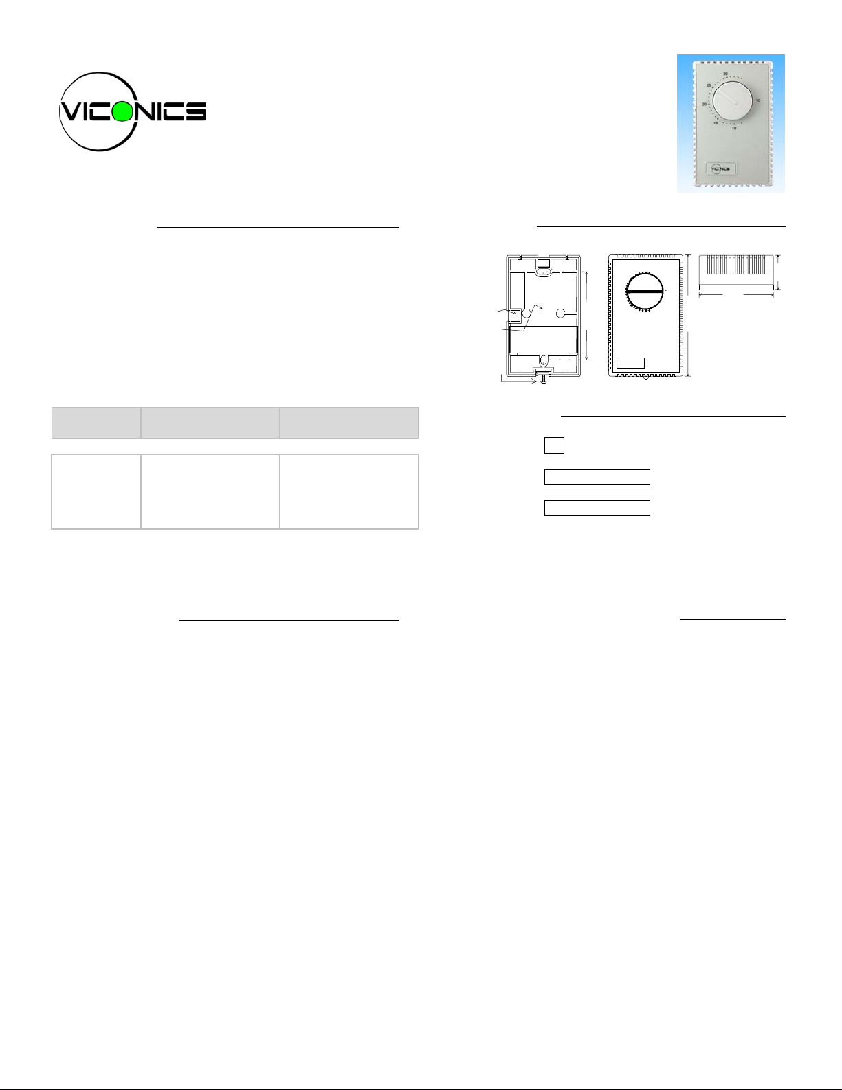
DIMENSIONS
WIRING
FROM TOP
OR FROM BACK
SECURITY SCREW
BASE
3.275"
( 83 mm )
90
80
70
F
60
50
4.5"
( 114 mm )
2.8"
( 71 mm )
HOW TO ORDER
C1011
Notes:
• Order changeover sensor separately.
• Vertical mounting is standard.
-
↓
00C = °C scale
↓
00F = °F scale
MODULATING FLOATING OUTPUT
1.275"
32 mm
Operating Conditions: 0 °C to 50 °C ( 32 °F to 122 °F )
0% to 95% R.H. non-condensing
Sens or: Local 47 K NT C thermistor
Resolution: ± 0.1 °C ( ± 0.2 °F )
Control accuracy: ± 0.2 ° C ( ± 0.4 °F ) ( calibrated )
Ranges: 10 °C to 32 °C ( 50 °F to 90 °F )
Proportional band f or r oom
temperature control: 1.8°C ( 3.2°F )
Floating output: Non isolated triac s: 30 Vac, ½ A max.
Power: 24 Vac -15%, +10% 50/60 Hz; 2 VA
This output is designed to give true PI modulation out of
floating actuator for VAV dampers and valves.
The thermostat is designed for operation with actuators that
have a running time of 1.5 to 2.5 minutes for the full open /
close stroke time.
The output is normally cooling but can be reversed to
heating mode with 2 different methods:
• Auto changeover to heating mode with a supply
sensor.
A remote supply sensor can be used for each thermostat.
Supply temperature > 78°F (26°C) = heating mode
Supply temperature < 75°F (24°C) = cooling mode
Hysterisys is 3°F (2°C)
• Auto changeover to heating mode with a dry contact.
A closed contact on the changeover input will change
operation of the floating output to heating mode.
Open contact = cooling mode
Closed contact = heating mode
1
Page 2
Characteristics of changeover sensor 47 KΩ
Temperature °F Temperature °C Sensor resistance
150.0 °F 65.6 °C 9.610 Kohm
140.0 °F 60.0 °C 11.700 Kohm
130.0 °F 54.4 °C 14.342 Kohm
120.0 °F 48.9 °C 17.682 Kohm
110.0 °F 43.3 °C 21.940 Kohm
100.0 °F 37.8 °C 27.412 Kohm
90.0 °F 32.2 °C 34.483 Kohm
80.0 °F 26.7 °C 43.704 Kohm
70.0 °F 21.1 °C 55.834 Kohm
60.0 °F 15.6 °C 71.866 Kohm
50.0 °F 10.0 °C 93.340 Kohm
40.0 °F 4.4 °C 122.298 Kohm
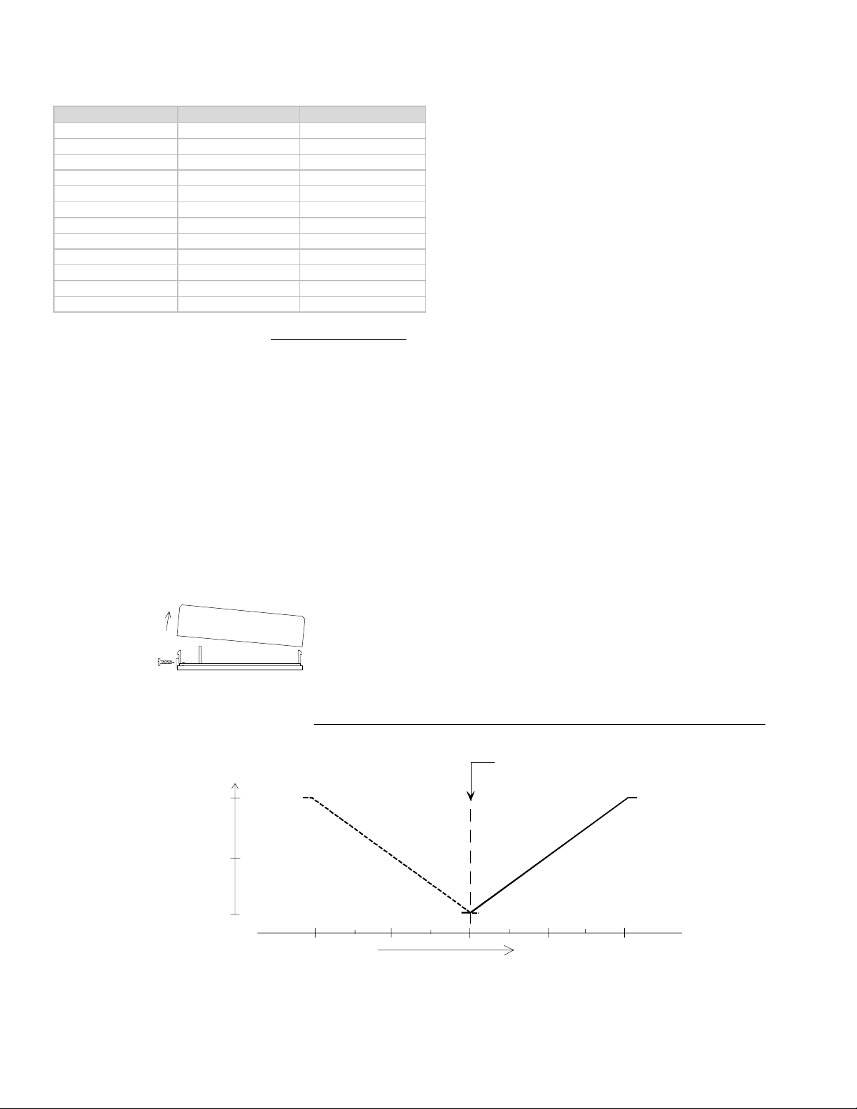
THERMOSTAT INSTALLATION
Important.
Electronic controllers require special care for wiring
and startup. To avoid problems, carefully follow the
procedures below.
Be sure to have all the literature on hand for all components
installed: controller, actuators, relay, etc...
Look at the wiring diagrams, and study them carefully. Be
sure that you understand how the system is supposed to
work.
Make the wiring according to the wiring diagrams. Respect
polarity for power terminals # 3 & # 4 between multiple
controllers if the same transformer is used.
Remove security screw on left side of thermostat cover.
•
Open up by pulling on the bottom side of thermostat.
•
A) Location:
1- Shouldn’t be installed on outside wall.
2- Must be installed away from any heat source.
3- Shouldn’t be affected by direct sun radiation.
4- Nothing must restrain vertical air circulation to the
thermostat.
B) Installation:
1- Pull out cables 6” out of the wall.
2- Wall surface must be flat and clean.
3- Separate the thermostat and the base by pulling
the cover by the bottom (same as the security
screw.)
4- Insert cable in the central hole of the base.
5- Align the base and mark the location of the two
mounting holes on the wall. Install proper side of
base up.
6- Install shields in the wall.
7- Insert screws in mounting holes on each side of the
base. DO NOT OVERTIGHTEN!
8- Strip each wire 1/4 inch.
9- Insert each wire according to wiring diagram.
10- Reinstall the cover ( top side first ) and gently push
back extra wire length in the hole in the wall.
11- Install security screw.
CONTROL CURVES AND SEQUENCE
SETPOINT DIAL
Opened
100%
50 %
Device
opened
Heating mode
changeover
input active
Device
opened
Cooling mode
Closed
0%
Device closed
Temperature increase
2
Page 3

TYPICAL APPLICATIONS
Pressure Dependent VAV
Modulating Floating
VAV Actuator
90
80
F
70
60
50
Room Temperature Control
Minimum & Maximum Position
Adjusted on the actuator
C/over
Common
24 Vac
Close
Open
2
3
4
5
6
Pressure Dependent VAV With:
Cool / Heat Auto Changeover Input
Changeover
Sensor
Room Temperature Control
Minimum & Maximum Position
Adjusted on the actuator
Modulating Floating
VAV Actuator
90
80
F
70
60
50
Supply air
temper ature senso r
C/over
2
Common
24 Vac
Close
Open
3
4
5
6
Valve Control With Room Thermostat ( Cooling Only )
Modulating Floating
Valve Cooling
90
80
F
70
60
50
Room Temperature
Control Thermostat
Modulating Floating
Valve Heating
90
80
F
70
60
50
Room Temperature
Control Thermostat
C/over
2
Common
24 Vac
Close
Open
3
4
5
6
Valve Control With Room Thermostat ( Heating Only )
C/over
2
Common
24 Vac
Close
Open
3
4
5
6
3
Page 4

Valve Control With Room Thermostat With:
Cool / Heat Auto Changeover Input
Modulating Floating Valve
Heating and/or Cooling
Optional Water
Supply Sensor
90
80
F
70
60
50
Room Temperature
Control Thermostat
C/over
Common
24 Vac
Close
Open
2
3
4
5
6
Supply water
temper ature sensor
24 VAC POWER AND FLOATING ACTUATOR TYPICAL WIRING
Power Supply 24 Vac -15% +10% 50/60 HZ 2 VA
•
If operation of the actuator is reversed, flip the reversing switch on
•
the actuator or reverse wires #5 & #6.
Note: terminals 2 and 3 can be wired together between each
•
thermostat if polarity is respected
Important: if using a common transformer, respect polarity ( Common
•
and 24 Vac between thermostats and actuator )
Common
24 Vac
Close
Open
3
4
5
6
Common
Close
Open
Modula ting floatin g actuat or
Open / Close type
Install 1 actuator
per thermostat
CHANGEOVER INPUT TYPICAL WIRING
1 SUPPLY CHANGEOVER SENSOR PER THERMOSTAT ( 1 SUPPLY SENSOR PER THERMOSTAT )
Auto changeover input using an S60, S70 duct supply sensor or S90
immersion supply sensor
• Supply temperature > 78°F (26°C) = Heating mode
• Supply temperature < 75°F (24°C) = Cooling mode
Cool / heat automatic
changeover input
Common
2
Changeove r sensor
3
• Hysterisys is 3°F (2°C) between heating and cooling
MULTIPLE TRANSFORMERS ( 1 DRY CONTACT FOR ALL THERMOSTATS )
Open contact = Cooling mode. Closed contact = Heating mode
24 Vac
Transformer
Primary
24 Vac
Common
Changeover
Input
4
24 Vac
3
2
Thermostat
Transformer
Primary
Do Not Ground Any
Transformer To Earth
Cool / Heat
Changeover Contact
24 Vac
Common
Changeover
Input
4
3
2
Thermostat
SINGLE TRANSFORMER ( 1 DRY CONTACT FOR ALL THERMOSTATS )
Open contact = Cooling mode. Closed contact = Heating mode
Primary Transformer
24 Vac
Common
4
3
24 Vac
Common
4
3
24 Vac
Cool / Heat
Changeover
Input
2
Thermostat
Viconics Electronics Inc. 9245, Langelier Blvd, St-Leonard, Quebec, Canada H1P 3K9 www.viconics.com
Changeover
Input
LIT-C1011-E01
2
Thermostat
Changeover Contact
sales@viconics.com
4
 Loading...