

Page 1

Origin Setup and Maintenance Guide
© Copyright 2018 Vicon Motion Systems Limited. All rights reserved.
Vicon Motion Systems Limited reserves the right to make changes to information in this document without notice.
Companies, names, and data used in examples are fictitious unless otherwise noted. No part of this publication may be
reproduced, stored in a retrieval system, or transmitted in any form or by any means, electronic or mechanical, by
photocopying or recording, or otherwise without the prior written permission of Vicon Motion Systems Ltd.
Vicon® is a registered trademark of Oxford Metrics plc. Vicon Beacon™, Vicon Blade™, Vicon Control™, Vicon Evoke™,
Vicon Lock™, Vicon Lock+™, Vicon Lock Lab™, Vicon Lock Studio™, Vicon MX™, Vicon Nexus™, Vicon Origin™,
Vicon Pegasus™, Vicon ProCalc™, Vicon Pulsar™, Vicon Shōgun™, Vicon Studio™, T-Series™, Vicon Tracker™,
Vicon Vantage™, Vicon Vero™, Vicon Vertex™, Vicon Viper™, and Vicon Vue™ are trademarks of Oxford Metrics plc.
VESA® is a registered trademark owned by VESA (www.vesa.org/about-vesa/). Other product and company names
herein may be the trademarks of their respective owners. For full and up-to-date copyright and trademark
acknowledgements, visit https://www.vicon.com/vicon/copyright-information.
Vicon Motion Systems is an Oxford Metrics plc company.
Email: [email protected] Web: http://www.vicon.com
Contents
DRAFT
About this guide............................................................................. 3
Introducing the Origin system ..................................................... 4
Origin system components........................................................5
Pulsar status LEDs and button ................................................. 7
Using the Pulsar button.............................................................8
Battery run time ..........................................................................9
Setting up an Origin system....................................................... 10
Start Evoke and load tracking objects ...................................11
Turn on Beacon, check status and set pairing mode.......... 12
Turn on clusters and pair with a Beacon............................... 13
Preparing Origin for a live experience.......................................15
Maintaining an Origin system .................................................... 16
Replace a failed cluster............................................................ 17
Unpair a cluster ......................................................................... 18
Monitor status ........................................................................... 19
Install in multiple volumes...................................................... 20
Manage object groups for gear up/gear down..................... 21
Hardware specifications for Origin systems............................ 23
Page 2

Origin
Setup &
Maintenance
Guide
Vicon Motion Systems Ltd. 11-Oct-2018 Page 2 of 44
Viper camera specification..................................................... 24
DRAFT
Cluster specification ............................................................... 26
Beacon specification................................................................ 27
Charger specification .............................................................. 28
Origin system safety and regulatory information...................29
Radio and television interference regulatory information.30
Environmental regulations (UK & EU customers)............... 34
CE Declaration of Conformity (Vicon Pulsar) .......................37
CE Declaration of Conformity (Vicon Viper)........................ 38
Specific Absorption Rate (SAR) certification...................... 39
Other important safety information...................................... 40
Page 3

Origin
Setup &
Maintenance
Guide
Vicon Motion Systems Ltd. 11-Oct-2018 Page 3 of44
About this guide
DRAFT
This guide provides information on system setup and maintenance for
operators of the Origin system from Vicon.
Page 4

Origin
Setup &
Maintenance
Guide
Vicon Motion Systems Ltd. 11-Oct-2018 Page 4 of44
Introducing the Origin system
DRAFT
The following topics provide an introduction to the Origin system:
• Origin system components (page 5)
• Pulsar status LEDs and button (page 7)
• Using the Pulsar button (page 8)
• Battery run time (page 9)
Page 5
Origin
Setup &
Maintenance
Guide
Vicon Motion Systems Ltd. 11-Oct-2018 Page 5 of44
Origin system components
DRAFT
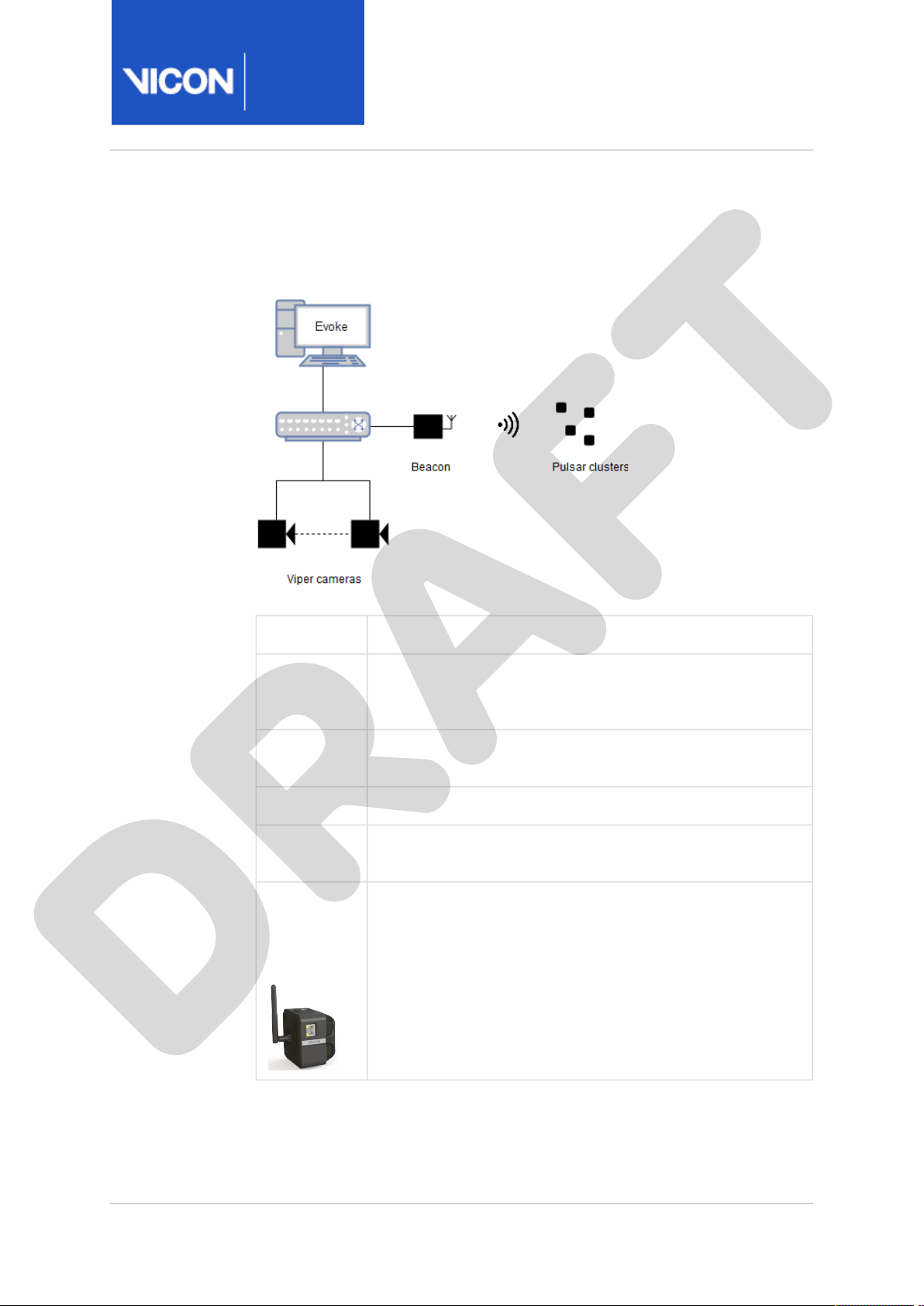
The Origin system comprises the following components:
Component Description
PC running
Vicon Evoke
software
Viper
cameras
PoE switch Spec/requirements TBC
Ethernet
cabling
Vicon
Beacon
wireless
synchroniza
tion unit
Spec/requirements TBC
Evoke is the Vicon app that controls Vicon devices and
outputs object poses via the DataStream SDK.
Approved description to come - with RGB status LED, IR
positioning LED, temperature sensors and accelerometer.
Standard RJ-45 terminated Cat5e cable
Vicon master synchronization unit whose main function
is to receive the Vicon Ethernet synchronization pulse
from the PoE+ and broadcast this wirelessly to Pulsar
clusters. It broadcasts the sync signal over Ethernet for
the cameras and over the radio at 2.4 GHz for the
clusters. This ensures the cluster LEDs are on only during
the camera exposure period, maximizing power
efficiency.
Page 6
Origin
Setup &
Maintenance
Guide
Vicon Motion Systems Ltd. 11-Oct-2018 Page 6 of44
Component Description
DRAFT
Pulsar
clusters
Micro-USB
charger
cable
Note that an additional app (TBC) is required to control Evoke and
connected Vicon devices.
Synchronized active tracking objects containing eight
LEDs that can be configured inunique LED patterns to
allow for tracking by the Evoke software. The clusters are
battery-operated and rechargeable through a standard
micro-USB connection.
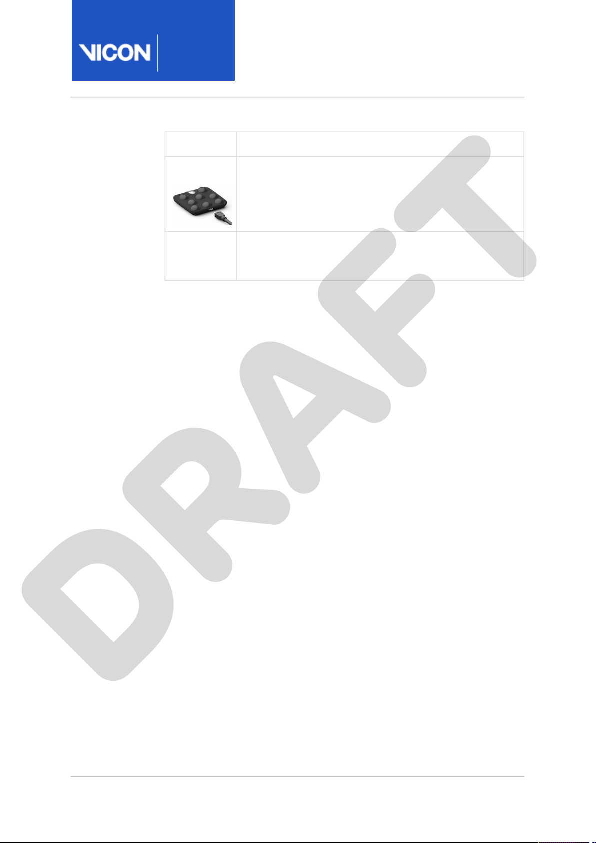
Standard micro-USB cable?
Page 7

Origin
Setup &
Maintenance
Guide
Vicon Motion Systems Ltd. 11-Oct-2018 Page 7 of44
Pulsar status LEDs and button
DRAFT
LED status Description
Green on Pulsar battery is charging*
Green off Pulsar battery is fully charged
Red on Pulsar battery low (<=20%)
Red off Pulsar battery has charge (>20%)
Blue off Radio disabled
Blue on Pulsar paired to Beacon
Blue on → Blue off (slow
pulsing)
Blue on → Blue off (fast
pulsing)
Red on → Red off → Blue
on → Blue off → Green on
→ Green off
Red on → Red off → Blue
on → Blue off → Green on
→ Green off (sequence
repeating)
* To ensure the charge indication LEDs are visible, the cluster automatically
switches on when plugged into the charger.
Available user commands:
• Status LEDs can be disabled.
• Enable/disable selection of Pulsar.
Pulsar on and paired but not receiving
comms from Beacon (will be in continuous
mode)
Pulsar on but not paired (will be in
continuous mode)
Boot sequence
Cluster selected in software
Page 8

Origin
Setup &
Maintenance
Guide
Vicon Motion Systems Ltd. 11-Oct-2018 Page 8 of44
Using the Pulsar button
DRAFT
To Do this
Turn on cluster On a cluster that is turned off, give the button a
Turn off cluster On cluster that is turned on, press the button for 2
single short press.
seconds.*
Reboot cluster
(retains settings)
Unpair cluster
from Beacon
*Can be disabled in software to prevent accidental use.
On cluster that is turned on, press the button for 10
seconds.*
During the 10-second period after booting only,
double-press the button.
Page 9

Origin
Setup &
Maintenance
Guide
Vicon Motion Systems Ltd. 11-Oct-2018 Page 9 of44
Battery run time
DRAFT
The following measurements have been performed with multiple prototype
units that are representative of final production hardware. They are
presented here to assist Dreamscape in specifying the number of units to
provide for their setup. However, the final numbers stated in released
documentation may differ once extended testing has been complete. Leave
in for now?****
Condition LED power
setting
Running continuously 75% 14h 8h
50:50 duty cycle IR LEDs on/off
(radio and status LEDs still on)
50:50 duty cycle IR LEDs on/off
(radio and status LEDs still on)
75% 20h 12h
100% 18h 11h
Run time Estimated
run time
after 500
charge
cycles
Page 10

Origin
Setup &
Maintenance
Guide
Vicon Motion Systems Ltd. 11-Oct-2018 Page 10 of44
Setting up an Origin system
DRAFT
To set up your Origin system, complete the following procedures:
• Start Evoke and load tracking objects (page 11)
• Turn on Beacon, check status and set pairing mode (page 12)
• Turn on clusters and pair with a Beacon (page 13)
Important
Before you begin, ensure Beacon is connected to a powered PoE
switch and that this switch is connected to the host PC, which runs
Evoke.
Page 11

Origin
Setup &
Maintenance
Guide
Vicon Motion Systems Ltd. 11-Oct-2018 Page 11 of44
Start Evoke and load tracking objects
DRAFT
1. Start Evoke.
2. On the Objecttab, click theImport Active Object button.
3. In the <name?> dialog box, select the number of objects required (up
to a maximum of 56 for Pulsar).
Evoke generates the requested number of objects, assigning each a
unique pattern of markers.
4. Ensure objects are appropriately named (e.g. Green_Hand_L), so they
can be easily matched with clusters. (Is it obvious how to rename
objects?)
Page 12

Origin
Setup &
Maintenance
Guide
Vicon Motion Systems Ltd. 11-Oct-2018 Page 12 of44
Turn on Beacon, check status and set pairing mode
DRAFT
1. Ensure Beacon is connected to a powered PoE switch and that this
switch is connected to the host PC running Evoke.
In Evoke, on theSystem tab, notice that in the Connectivitysection a
Beacon entry is displayed.
2. Ensure that the Beacon connection status is green.
If a radio error flag is displayed, Beacon was unable to find a clear radio
channel. This may be because other devices are transmitting at 2.4
GHz and are interferring with the sync signal (e.g. mobile phones or WiFi routers).
3. On the System tab, select Beacon and in the Properties pane? set the
Pairing Mode:
• Auto Enables unpaired clusters to pair to this Beacon.
• Whitelist Enables you to select specific clusters to pair.
Only one connected Beacon can be in pairing mode at a time (Beacons
in adjacent volumes may also be in pairing mode, but this is not
recommended).
Page 13

Origin
Setup &
Maintenance
Guide
Vicon Motion Systems Ltd. 11-Oct-2018 Page 13 of44
Turn on clusters and pair with a Beacon
DRAFT
1. On the cluster, press the power button to turn it on. (Note that it is
easiest to match physical labels with entries in the System tab if you
turn on clusters one at a time.)
The cluster automatically searches for a radio channel with a Beacon
pairing broadcast. It records the radio channel for communication with
this Beacon. This record persists when the cluster is turned off.
In Evoke, on the System tab, in the ActiveCluster section, a Cluster
entry is displayed.
2. Ensure that the cluster connection status isblue(connected but not
programmed with a marker pattern).
<img>
Note that the cluster battery level is indicated by status icon.
<img>
If any other icon is displayed, see Cluster error icons (page 14) to
troubleshoot possible issues.
3. Assign a tracking object (LED pattern) to the cluster. To do this, on the
System tab, select a cluster and from the Patterndrop-down menu,
choose the corresponding object pattern.
Note that a cluster can be assigned a pattern from any object, but to
avoid confusion it is best to label clusters according to their intended
location (e.g. Green_Hand_L or Red_Backpack_Top) and name objects
accordingly.
When you have assigned a pattern to the cluster:
• The pattern error icon clears from cluster entry.
• The cluster connection status turnsgreen(active with LEDs turned
on).
4. To confirm that the object is tracked and labeled correctly, check that
in the 3D Scene view, the object model is drawn and its label matches
the associated cluster(s).
5. When you have paired all the clusters, turn off pairing mode. To do this,
on the System tab select Beacon and set Pairing Mode to Off.
Cluster settings are stored in the System file (by default located at
\Users\Public\Documents\Vicon\Evoke1.0\LastRun\
n.System
located at
\Users\Public\Documents\Vicon\Evoke1.0\LastRun\
n.Subjects
). Object settings are stored in the Subjects file (by default
C:
). Settings are auto-saved on exit.
<username>
<username>
C:
\LastRu
\LastRu
Page 14

Origin
Setup &
Maintenance
Guide
Vicon Motion Systems Ltd. 11-Oct-2018 Page 14 of44
• To disable a cluster, on the System tab, select the cluster and clear the
DRAFT
Enabledcheck box.
The cluster connection status turns yellow. The marker LEDs turn off, to
reduce power consumption when not in active use. Move to where
relevant
Cluster error icons
On the System tab, in the ActiveCluster section, cluster error icons indicate
the status of the cluster: <add images>
Error Meaning
Hardware
error
Radio error Evoke is not receiving status updates from the cluster.
Pattern error The cluster has not been assigned a pattern, or multiple
A physical problem has been reported by the cluster.
enabled devices are using the same pattern.
Page 15

Origin
Setup &
Maintenance
Guide
Vicon Motion Systems Ltd. 11-Oct-2018 Page 15 of44
Preparing Origin for a live experience
DRAFT
Before using clusters in a live experience, make the following checks:
1. Ensure clusters are paired with a Beacon in the volume (see Setting up
an Origin system (page 10)).
2. Ensure that the Beacon is enabled. This is shown by the following
indicators:
• On the System tab, the Connectivity section displays a Beacon entry.
• Beacon connection status is green.
• Beacon error flags are clear.
• On the System tab, select Beacon and then select the Enabled
checkbox. (ensure the Enabled checkbox is selected?)
3. Turn on the clusters and check their status in Evoke:
• Cluster entries appear on the System tab, in the Active Cluster
section.
• Cluster connection status is green for all clusters.
• Battery levels are sufficient for the experience.
• Error flags are clear.
• Objects are tracked and labeled in the 3D Scene.
Disable Beacon features (optional):
• Set Pairing Mode toOff
This removes the pairing flag from the Beacon sync broadcast, which
prevents any unpaired clusters trying to connect to it.
Start camera calibration auto heal session:
• This tells the automatic camera calibration repair mechanism to start
collecting data.
For successful calibration repair, objects must be tracked in the volume,
and all cameras must see some data at some point during the session.
Page 16

Origin
Setup &
Maintenance
Guide
Vicon Motion Systems Ltd. 11-Oct-2018 Page 16 of44
Maintaining an Origin system
DRAFT
For information about maintaining your Origin system, see the following
topics:
• Replace a failed cluster (page 17)
• Unpair a cluster (page 18)
• Monitor status (page 19)
• Install in multiple volumes (page 20)
• Manage object groups for gear up/gear down (page 21)
Page 17

Origin
Setup &
Maintenance
Guide
Vicon Motion Systems Ltd. 11-Oct-2018 Page 17 of44
Replace a failed cluster
DRAFT
Depending on the failure mode, the affected cluster may show as
disconnected (red X icon) on the System tab, or it may show error icons.
To replace a cluster:
1. Turn off the failed cluster using the power button.
2. Ensure that the replacement cluster is paired with the Beacon in the
volume.
3. Replace the failed cluster with the replacement cluster and turn on the
replacement.
To assign the pattern from the failed cluster:
1. Ensure the replacement cluster is displayed in the System tab with a
blueconnection status icon(connected but not programmed with a
marker pattern).
2. On the Systemtab, select it and from the Patterndrop-down list,
choose the pattern matching the device location.
Note that unassigned patterns or patterns assigned to a disconnected
device are displayed at the top of the list.
Check that the connection status turns green(active and programmed
with a marker pattern).
Page 18

Origin
Setup &
Maintenance
Guide
Vicon Motion Systems Ltd. 11-Oct-2018 Page 18 of44
Unpair a cluster
DRAFT
You can unpair a cluster from a Beacon within Evoke if it is currently
connected. To do this:
1. Ensure that the current Beacon is not in pairing mode at this point, or
2. On the Systemtab, right-click the cluster and from the context menu,
If the cluster is not connected to a Beacon, you can unpair it using the
multi-function button on the cluster. To do this:
1. Hold the power button for 4 seconds (TBC) then release.
2. Press the button twice to unpair the cluster.
the cluster may reconnect to it.
choose the Unpair option.
The cluster pairing channel is cleared, so it immediately enters pairing
mode to search for a new Beacon.
• The Beacon clears its record of the cluster.
• The cluster entry is cleared from theSystem tab.
The cluster reboots and starts a flash sequence to indicate that it can
be unpaired for 10 seconds.
It automatically returns to pairing mode, searching for Beacons in
pairing mode.
Page 19

Origin
Setup &
Maintenance
Guide
Vicon Motion Systems Ltd. 11-Oct-2018 Page 19 of44
Monitor status
DRAFT
The Live API <xref to Live API doc> provides functionality for querying
device status and registering for callbacks on value changes. This can be
used to monitor battery levels or cluster error flags.
Page 20

Origin
Setup &
Maintenance
Guide
Vicon Motion Systems Ltd. 11-Oct-2018 Page 20 of44
Install in multiple volumes
DRAFT
Between 4 and 10 Beacons can share the same radio space, depending on
the number of other devices on 2.4 GHz nearby (for example, Wi-Fi routers
and mobile phones).
To prevent clusters pairing with the wrong Beacon, set only one Beacon to
pairing mode at a time.
Page 21
Origin
Setup &
Maintenance
Guide
Vicon Motion Systems Ltd. 11-Oct-2018 Page 21 of44
Manage object groups for gear up/gear down
DRAFT
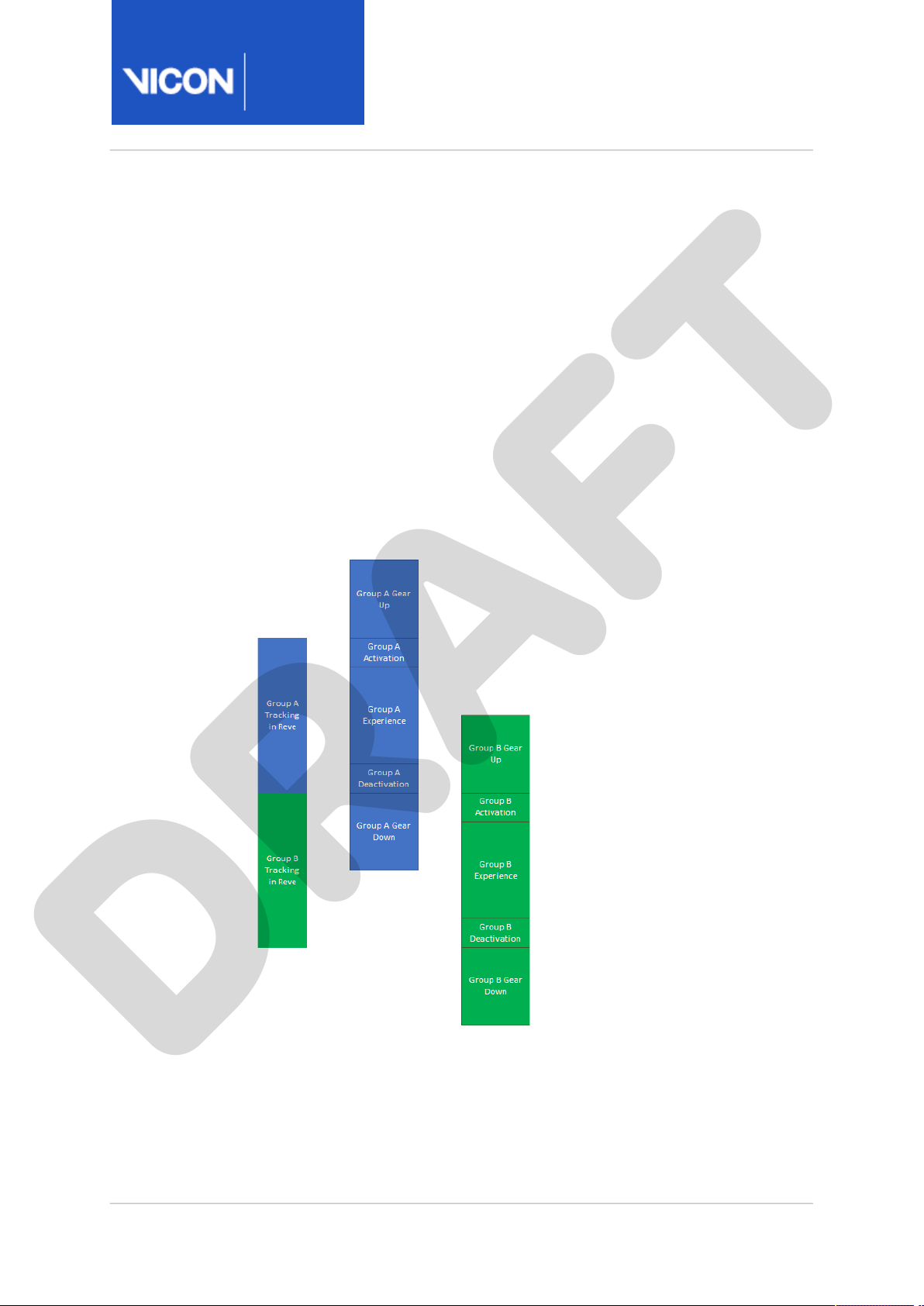
Maximizing volume uptime requires overlapping groups of participants, so
that one group is gearing up/down while another is going through the
experience.
The number of patterns required for two groups of participants may exceed
the maximum number of unique patterns. In this case, the operator must
manage enabling and disabling groups of devices.
In Evoke, a single set of objects is loaded and the operator manages which
cluster devices are assigned to the objects.
The Live API <XREF> provides access to devices for easier management of
device groups.
Page 22

Origin
Setup &
Maintenance
Guide
Vicon Motion Systems Ltd. 11-Oct-2018 Page 22 of44
1. Gear up
DRAFT
a. Enable group clusters:
• On System tab, select clusters in group and select the
Enabled check box.
b. Check cluster statuses are green and error flags are clear.
c. Participants move to calibration area.
d. Check that all objects are tracking well.
2. Experience
a. Send Start Experience command.
b. Participants move into volume and experience begins.
c. Experience ends.
d. Send Stop Experience command.
3. Gear down
a. Participants move to calibration area.
b. Disable group clusters:
• On System tab, select clusters in group and clear the Enabled
check box.
It is assumed that there are four areas involved:
• Gear up/gear down area for Group A
• Gear up/gear down area for Group B
• Calibration area for group activation/deactivation and tracking checks
• Tracking volume (where experience takes place)
In the gear-up/gear down areas, the clusters must be able to connect to the
Beacon, enabling the software to monitor status and battery level.
Connectivity depends on the physical layout and distance from the Beacon.
The calibration area must be adjacent to the main tracking volume, both for
seamless tracking and for good radio connectivity.
Page 23

Origin
Setup &
Maintenance
Guide
Vicon Motion Systems Ltd. 11-Oct-2018 Page 23 of44
Hardware specifications for Origin systems
DRAFT
See the following specifications:
• Viper camera specification (page 24)
• Cluster specification (page 26)
• Beacon specification (page 27)
• Charger specification (page 28)
Page 24

Origin
Setup &
Maintenance
Guide
Vicon Motion Systems Ltd. 11-Oct-2018 Page 24 of44
Viper camera specification
DRAFT
The following table provides technical specifications and performance
indicators for Vicon Viper cameras.
Component Specification
Resolution 2.2 MP
Frame rate (minimum) 30 fps
Frame rate (full frame) 240 fps
Sensor diagonal 12.75 mm
Pixel shutter type Global shutter
Pixel size 5.5 µm square
Lens Tamron 6.5 mm fixed
Effective FOV (H x V) 81.8 x 49.4
2048 * 1088
Optical filter Long-pass wavelength matched dye filter
Maximum temperature
Minimum temperature
Maximum humidity TBC
Maximum power
consumption
Connectivity Single RJ-45 connection for Cat6 cabling.
Weight 277 g
Camera external
dimensions
1 (page 25)
35°C
1 (page 25)
-5°C
6 W
Carries power and data and conforms to IEEE
802.3af-2003 (15.4W) standard.
H x W x D: 80 x 80 x 75 mm
Page 25

Origin
Setup &
Maintenance
Guide
Vicon Motion Systems Ltd. 11-Oct-2018 Page 25 of44
1. Operating temperature: While Vicon cameras may operate outside the
DRAFT
given limits, these are the temperatures to which Vicon has tested the
cameras. If the cameras are operated outside of these limits, image
quality may be degraded, the external surface temperatures may
exceed the relevant safety limits, and any failures are not covered
under warranty.
Page 26

Origin
Setup &
Maintenance
Guide
Vicon Motion Systems Ltd. 11-Oct-2018 Page 26 of44
Cluster specification
DRAFT
Component Specification
Power Internal 3.7 V nominal lithium polymer
IR wavelength 850 nm
battery (fixed)
Distinct LED patterns in
use
Patterning 5 LEDs on of 8 fitted
LEDs for status indication Battery (Green)
Physical multifunction
switch
Run time 10hrs (min)
Charge interface USB micro-B receptacle
Recharge time to 80% 1 hr (max)
Recharge time to 100% 3 hr (max)
Range (optical) To suit 7 x 7 x 3 m volume
Range (RF) To suit 7 x 7 x 3 m volume
24(min), 56 (aim)
Radio (Blue)
Sensor failure (Red)
Power, sleep, pairing, reboot
IP rating IP50 (min)
Page 27

Origin
Setup &
Maintenance
Guide
Vicon Motion Systems Ltd. 11-Oct-2018 Page 27 of44
Beacon specification
DRAFT
Component Specification
Power Power over Ethernet (PoE) class TBD
device
Number of clusters per
Beacon
Number of Beacons per
volume
Number of Beacons
operating simultaneously
in adjacent volumes
Sync frequency 240 fps (max)
RF frequency band 2.4 GHz
Range (RF) To suit 7 x 7 x 3 m volume (min)
*Depending on RF spectrum occupancy at site check
24 (min), 56 (aim)
1
4 (min), 10 (aim)*
Page 28

Origin
Setup &
Maintenance
Guide
Vicon Motion Systems Ltd. 11-Oct-2018 Page 28 of44
Charger specification
DRAFT
USB cable charging from off-the-shelf charger.
Page 29

Origin
Setup &
Maintenance
Guide
Vicon Motion Systems Ltd. 11-Oct-2018 Page 29 of44
Origin system safety and regulatory information
DRAFT
The terms “device” or “wireless device” used in this section refer to your
Beacon Model MSU1 and sets of Pulsar LED Cluster Model P1 wearable
products.
Read this information before using your device.
• Pulsar radio and television interference regulatory information (page 30)
• Pulsar environmental regulations (United Kingdom and European Union
customers) (page 34)
• CE Declaration of Conformity (Vicon Pulsar) (page 37)
• CE Declaration of Conformity (Vicon Viper) (page 38)
• Specific Absorption Rate (SAR) certification (page 39)
• Other important safety information (page 40)
Page 30

Origin
Setup &
Maintenance
Guide
Vicon Motion Systems Ltd. 11-Oct-2018 Page 30 of44
Radio and television interference regulatory information
DRAFT
This topic contains information concerning compliance with regulations of
radio and television interference.
• For United States of America customers (page 30)
• For Canadian customers (page 31)
• For Australian and New Zealand customers (page 32)
• For Japanese customers (page 33)
• For The People’s Republic of China customers (page 33)
For United States of America customers
Federal Communications Commission (FCC) Part 15 Information
Pursuant to part 15.21 of the FCC Rules, you are cautioned that changes or
modifications not expressly approved by Vicon Motion Systems Ltd could
void your authority to operate the device. This device complies with part 15
of the FCC Rules. Operation is subject to the two conditions: (1) This device
may not cause harmful interference, and (2) this device must accept any
interference received, including interference that may cause undesired
operation.
Note: This equipment has been tested and found to comply with the limits
for a Class B digital device, pursuant to part 15(c) of the FCC CFR47 rules.
These limits are designed to provide reasonable protection against harmful
interference in a residential installation. This equipment generates, uses
and can radiate radio frequency (RF) energy and, if not used in accordance
with the instructions, may cause harmful interference to radio
communications. However, there is no guarantee that interference will not
occur in a particular application. If this equipment does cause harmful
interference to radio or television reception, which can be determined by
turning the equipment off and on, the user is encouraged to try to correct
the interference by one or more of the following measures:
• Reorient or relocate the receiving antenna.
• Increase the separation between the equipment and receiver.
• Consult the dealer or an experienced radio/TV technician for help.
Page 31

Origin
Setup &
Maintenance
Guide
Vicon Motion Systems Ltd. 11-Oct-2018 Page 31 of44
FCC Notice and Cautions
DRAFT
The device may cause TV or radio interference if used in close proximity to
receiving equipment. The FCC can require you to stop using the equipment
if such interference cannot be eliminated.
Cautions: Any changes or modifications to your device not expressly
approved by Vicon Motions Systems Ltd could void your warranty for this
equipment and void your authority to operate this equipment. Only use
approved batteries. The use of any unauthorized accessories may be
dangerous and void the device warranty if said accessories cause damage
or a defect to the device. Although your device is quite sturdy, it is a
complex piece of equipment and can be broken. Avoid dropping, hitting,
bending or sitting on it.
This equipment complies with FCC radiation exposure limits set forth for an
uncontrolled environment. End users must follow the specific operating
instructions for satisfying RF exposure compliance. This transmitter must
not be co-located or operating in conjunction with any other antenna or
transmitter.
The published FCC IDs are:
Beacon DMR-VICMSU1 and Pulsar LED Clusters DMR-VICP1.
For Canadian customers
Under Industry Canada regulations, this radio transmitter may only operate
using an antenna of a type and maximum (or lesser) gain approved for the
transmitter by Industry Canada.
To reduce potential radio interference to other users, the antenna type and
its gain should be so chosen that the equivalent isotropically radiated
power (e.i.r.p.) is not more than that necessary for successful
communication.
This device complies with Industry Canada licence-exempt RSS standard(s).
Operation is subject to the following two conditions: (1) this device may not
cause interference, and (2) this device must accept any interference,
including interference that may cause undesired operation of the device.
Conformément à la réglementation d'Industrie Canada, le présent émetteur
radio peut fonctionner avec une antenne d'un type et d'un gain maximal
(ou inférieur) approuvé pour l'émetteur par Industrie Canada.
Page 32

Origin
Setup &
Maintenance
Guide
Vicon Motion Systems Ltd. 11-Oct-2018 Page 32 of44
Dans le but de réduire les risques de brouillage radioélectrique à l'intention
DRAFT
des autres utilisateurs, il faut choisir le type d'antenne et son gain de sorte
que la puissance isotrope rayonnée équivalente (p.i.r.e.) ne dépasse pas
l'intensité nécessaire à l'établissement d'une communication satisfaisante.
Le présent appareil est conforme aux CNR d'Industrie Canada applicables
aux appareils radio exempts de licence. L'exploitation est autorisée aux
deux conditions suivantes : (1) l'appareil ne doit pas produire de brouillage,
et (2) l'utilisateur de l'appareil doit accepter tout brouillage radioélectrique
subi, même si le brouillage est susceptible d'en compromettre le
fonctionnement.
The published COMPANY NUMBER and UPN NUMBER are:
Beacon 11323A-VICMSU1 and Pulsar LED Clusters 11323A-VICP1.
For Australian and New Zealand customers
The product complies with the requirements of the relevant
Australian Communications and Media Authority Standards made under
the following Notices:
•
Radiocommunications (Compliance Labelling - Devices) Notice 2014
made under section 182 of the
•
Radiocommunications Labelling (Electromagnetic Compatibility) Notice
2008
made under section 182 of the
•
Radiocommunications (Compliance Labelling – Electromagnetic
Radiation) Notice 2014
Radiocommunications Act 1992
Supplier’s declaration of conformity available upon request.
made under section 182 of the
Radiocommunications Act 1992
Radiocommunications Act 1992
.
;
;
Page 33

Origin
Setup &
Maintenance
Guide
Vicon Motion Systems Ltd. 11-Oct-2018 Page 33 of44
For Japanese customers
DRAFT
Conformity Assessment Body (CAB ID 205) with respect to the Japan/EU
MRA, declares that the VICON®Beacon Model MSU1 and sets of Pulsar LED
Cluster Model P1 complies with the Certification by Type of the Ordinance
Concerning Technical Regulations Conformity Certification, etc. of
Specified Radio Equipment (MPT Ordinance No. 37 of 1981).
Category of the Specified Radio Equipment Article 2, Paragraph 1, Item (19).
Class of Emission F1D
Frequency 2402 MHz–2480 MHz
Antenna Power 2.3 mW/MHz (Cluster and Beacon)
Antenna Gain 1.5 dBi (cluster), 2.0 dBi (Beacon)
For The People’s Republic of China customers
The wireless device is classified as F Type General Micro power (short
range) radio transmission equipment in that:
• Transmission power <10 mW EIRP limit
• Frequency tolerance <75 kHz
• Operates within 2400-2483.5 MHz
• Utilizes an IEEE 802.14.4 radio protocol
The State Radio Regulation Committee (SRRC) is administered by the
Ministry of Industry and Information Technology of the PRC (MIIT)’s Radio
Administration Bureau. As of 1st December 2016, the SRRC no longer
requires Type Approval for specific Low Power Short Range devices
including F Type not employing Bluetooth® radio protocols.
Page 34

Origin
Setup &
Maintenance
Guide
Vicon Motion Systems Ltd. 11-Oct-2018 Page 34 of44
Environmental regulations (UK & EU customers)
DRAFT
This section lists the directives that apply to Origin systems.
This information applies only to the United Kingdom and European Union
member states.
Vicon meets these European Commission directives concerning waste
electrical and electronic equipment:
• Directives 2002/95/EC and 2011/65/EU (for details, see Restriction of the
use of certain hazardous substances in electrical and electronic
equipment – RoHS and recast (RoHS 2) (page 34)).
• REACH Declaration of Conformity (page 34)
• Directive 2202/96/EC (for details, see Waste Electrical and Electronic
Equipment (WEEE) (page 35) ).
Restriction of the Use of certain Hazardous Substances in Electrical and
Electronic Equipment –RoHS and Recast (RoHS 2)
This device is fully RoHS (2002/95/EC provides that new electrical and
electronic equipment put on the market for the first time from 1 July 2006)
and RoHS 2-compliant. The European Union Directive 2011/65/EU1 provides
that new electrical and electronic equipment put on the market for the first
time from 3rd January 2014 shall not contain more than permitted levels
of lead, cadmium, mercury, hexavalent chromium, polybrominated
biphenyls (PBB), or polybrominated diphenyl ethers (PBDE; PentaBDE,
OctaBDE; DecaBDE), Mercury (Hg).
REACH Declaration of Conformity
Vicon Motion Systems Ltd is a manufacturer of electronic hardware. We are
therefore considered a “downstream user” as far as the REACH document is
concerned.
Vicon Motion Systems Ltd is therefore not obligated to register with the
European Agency for Chemicals ‘ECHA’.
Products sold by Vicon Motion Systems Ltd are “articles” as defined in
REACH (Article 3 Definitions). Moreover and under normal and reasonably
foreseeable circumstances of application, the articles supplied shall not
1 http://eur-lex.europa.eu/legal-content/EN/TXT/?uri=CELEX:32011L0065
Page 35

Origin
Setup &
Maintenance
Guide
Vicon Motion Systems Ltd. 11-Oct-2018 Page 35 of44
release any substance. For that, Vicon Motion Systems Ltd is neither
DRAFT
obligatory for registration nor for the creation of material safety data
sheets.
In order to assure our customers of the continual supply of reliable and safe
products, we ensure that our suppliers fulfill all requirements regarding
chemical substances and prepared materials.
Waste Electrical and Electronic Equipment (WEEE)
(Applicable in the European Union and other European countries with
separate collection systems)
The use of the symbol as a marking on the equipment,
accessories or literature indicates that this product and
its electronic accessories (e.g. USB cable) may not be
treated as household waste. By ensuring this product is
disposed of correctly, you will help prevent potential
negative consequences for the environment and human
health, which could otherwise be caused by inappropriate
waste handling of this product.
Household users should contact either their retailer where they purchased
this device, or their local government office, for details of where and how
they can take these items for environmentally safe recycling. Business
users should contact their supplier and check the terms and conditions of
the purchasing contract. This device and its electronic accessories should
not be mixed with other commercial waste for disposal.
Page 36

Origin
Setup &
Maintenance
Guide
Vicon Motion Systems Ltd. 11-Oct-2018 Page 36 of44
Correct disposal of batteries in this device
DRAFT
(Applicable in the European Union and other European countries with
separate battery systems)
The use of the symbol as a marking on the battery,
manual or packaging indicates that the battery in this
device should not be disposed of with other household
waste at the end of their working life. Where marked, the
chemical symbols Hg, Cd or Pb indicate that the battery
contains mercury, cadmium or lead above the reference
levels in EC Directive 2006/66. If batteries are not
properly disposed of, these substances can cause harm to
human health or the environment.
To protect natural resources, and to promote material reuse, please
separate batteries form other types of waste and recycle them through
your local, free battery return system.
The rechargeable battery incorporated in this device is not user
replaceable. For information on its replacement please contact Vicon
Motion Systems Ltd.
Page 37

Origin
Setup &
Maintenance
Guide
Vicon Motion Systems Ltd. 11-Oct-2018 Page 37 of44
CE Declaration of Conformity (Vicon Pulsar)
DRAFT
Declaration of Conformity
(Radio Equipment Directive 2014/53/EU)
We, Vicon Motion Systems Ltd
Unit 6, Oxford Industrial Park
Yarnton, Oxfordshire, OX5 1QU
UNITED KINGDOM
declare under our sole responsibility that the product
VICON Beacon Model MSU1
VICON Pulsar LED Clusters Model P1
to which the declaration relates, is in conformity with the following standards and/or other
normative documents.
SAFETY
EMC EN61326:2013; ETSI EN301 489-17 V2.2.1:2012
RADIO ETSI EN300 328 V2.1.1 (2016-11)
We hereby declare that all essential radio test suites have been carried out and that the
above named product is in conformity to all the essential requirements of Directive 1999/5/
EC. The technical documentation is kept at Vicon Motion Systems Ltd, Unit 6, Oxford
Industrial Park, Yarnton, Oxfordshire, OX5 1QU, UNITED KINGDOM that will be made
available on request.
T.M.L. Shannon, TD, PhD, FIE (Aust.), CPEng (Biomed.)
Director
3rd September 2018
1
1. Risk analysis performed under ISO14971:2012 in compliance with Medical Devices
Directive 93/42/EEC applied as amended by EU Council Directive 2007/47/EC of 5th
September 2007 as the product is wearable.
EN 60601-1:2006/A12: 2014
Latex Free
RF Exposure Evaluation RED 2014/53/EU Article 3(1)(a)
using the common technical requirements of ETSI EN301 489-1 V2.1.1
Covering wide band transmission systems; data transmission
equipment operating in the 2.4 GHz ISM band
Not a medical device. Not for use in an operating theatre, anaesthetic gas or oxygen-rich
environments. Not for use where there is a risk of compromising the essential performance
of medical electrical equipment. Not suitable for use in high magnetic flux, ionizing
radiation, sterile, or life- or safety-critical environments.
Page 38

Origin
Setup &
Maintenance
Guide
Vicon Motion Systems Ltd. 11-Oct-2018 Page 38 of44
CE Declaration of Conformity (Vicon Viper)
DRAFT
Declaration of Conformity
Electromagnetic Compatibility to EMC Directive 2004/108/EC
Electrical Safety to Low Voltage Directive 2006/95/EC.
We, Vicon Motion Systems Limited
Unit 6 Oxford Industrial Estate
Yarnton OX5 1QU
UNITED KINGDOM
declare that the VICON Viper Cameras manufactured by VICON MOTION SYSTEMS LIMITED
have been tested and demonstrated that all products of its own manufacture meet
2004/108/EC:
Electromagnetic Compatibility to:
EN60601-1-2:2015
General Requirements for Safety to:
Cameras EN60601-1:2006 + A12:2014
Network Hub UL60950-1, 2nd Edition
SIGNATURE
Thomas Shannon TD PhD FIE (Aust) CPEng (Biomed.)
Director
******
Not for use in an operating theatre anaesthetic gas or oxygen-rich environments. Not for
use where there is a risk of compromising the essential performance of medical electrical
equipment. Not suitable for use in high magnetic flux, ionising radiation, sterile, or life- or
safety-critical environments.
Page 39

Origin
Setup &
Maintenance
Guide
Vicon Motion Systems Ltd. 11-Oct-2018 Page 39 of44
Specific Absorption Rate (SAR) certification
DRAFT
For United States of American Customers (FCC)
For Standalone SAR exclusion consideration, when SAR Exclusion
Threshold requirement in KDB 447498 is satisfied, standalone SAR
evaluation for general population exposure conditions by measurement or
numerical simulation is not required. At 2405 MHz, effective isotropically
radiated power of the wearable LED cluster is 4.3 mW, and for the Beacon 5
mW effective radiated power, which will be less than the SAR Exclusion
Threshold (96.72 mW). For further information, please see clause 4.3 of
KDB 447498 D01 General RF Exposure Guidance.
This device has been granted authorization to be used in the United States
for all equipment exhibiting DMR-VICP1 and DMR-VICMSU1.
For Canadian Customers (ISED)
SAR evaluation is required if the separation distance between the user and/
or bystander and the antenna and/or radiating element of the device is less
than or equal to 20 cm, except when the device operates at or below the
applicable output power level (adjusted for tune-up tolerance) for the
specified separation distance. At 2405 MHz, equivalent isotropically
radiated power of the wearable device is 4.3 mW, which will be less than
the SAR Exclusion Threshold at distances of between ≥5 and ≤ 10 mm of
4-7 mW. The minimum distance between the cluster aerial and the
underside is 6.69 mm. The Beacon minimum safety distance is calculated
as 10.4 mm. For further information, please see clause 2.5.1 of RSS-102
Issue 5 March 2015.
These devices have been granted authorization to be used in Canada for all
equipment exhibiting 11323A-VICP1 and 11323A-VICMSU1.
For European Union Customers (RED)
Minimum safe distance for RF exposure, based on the
General Public exposure of EU Council Recommendation (1999/519/EC)
12 July 1999, on the limitation of exposure of the general public to electromagnetic fields (0 Hz to 300 GHz) was calculated for the wearable device
as:
Frequency (MHz) EIRP (dBm) Limit (W/m2) Min. safe distance (m)
2480 6.8 10 0.0062
Reference Levels for
of
Page 40

Origin
Setup &
Maintenance
Guide
Vicon Motion Systems Ltd. 11-Oct-2018 Page 40 of44
Other important safety information
DRAFT
• Only qualified personnel should service the device. Faulty service may be
dangerous and may invalidate any warranty applicable to the device.
• Do not store or carry flammable liquids, gases, or explosive materials in
the same compartments as the device, its parts, or accessories.
• For vehicles equipped with an air bag, remember that an airbag inflates
with great force. Do not place objects, including portable wireless
equipment near or in the area over the air bag or in the airbag
deployment area. If the wireless device is within the deployment area as
an air bag inflates, serious injury could result.
• Switch off the device off before boarding an aircraft. The use of wireless
devices in aircraft is illegal and may be dangerous to the aircraft’s
operation. Check with appropriate authorities before using any function
of the device while on an aircraft.
• The primary responsibility of every driver is the safe operation of his or
her vehicle. Do not engage in any activity while driving a moving vehicle
which may take your eyes off the road or become absorbed in any activity
that your ability to concentrate on the act of driving becomes impaired.
• Failure to observe these instructions may lead to the suspension or
denial of network services, or legal action, or both.
Battery use and safety
• The battery in this device is not intended to be replaced by the
consumer. If you believe the battery is damaged or needs to be replaced,
return the device for inspection and replacement.
• Do not let the device or battery come in contact with liquids. Liquids can
get into the device’s circuits, leading to corrosion. Even when the device
appears dry and appears to operate normally, the circuit could slowly
corrode and pose a safety hazard.
• Do not place the device in or near a heat source. Excessive heating can
damage the device and battery and could cause the device or the battery
to explode. Do not dry a wet or damp device with an appliance or heat
source such as a microwave oven, hair dryer, iron, or radiator. Avoid
leaving your device in your vehicle in high temperatures.
• Do not dispose of the device or battery in a fire. The device or battery
may explode when overheated.
• Avoid dropping the device. Dropping the device, especially on a hard
surface, can potentially cause damage. If you suspect damage to the
device or battery, return it for inspection.
Page 41

Origin
Setup &
Maintenance
Guide
Vicon Motion Systems Ltd. 11-Oct-2018 Page 41 of44
• Never use any battery that is damaged in any way.
DRAFT
• Warning. Use of a non-manufacturer approved batteries may present a
risk of fire, leakage, or other hazard. Manufacturer warranty does not
cover damage to the device caused by non-approved batteries.
• Do not use incompatible batteries and chargers. If using a powered USB
Hub always ensure that you use the manufacturer’s approved or
recommended power source. Some websites and second-hand dealers
not associated with reputable manufacturers and carriers, might be
selling incompatible or even counterfeit batteries and chargers. Please
refer to Vicon Motion Systems Ltd for advice. Misuse or use of
incompatible batteries and chargers could result in damage to the device
and a possible risk of fire, explosion, or leakage, leading to serious
injuries, damage to your device, or other serious hazard.
Operating environment
• Avoid temperature below 0oC/ 32oF or above 37oC/99oF.
• Do not expose your device to dust, dirt, or sand.
• Remember to follow any special regulations in force in any area, and
always switch your device off whenever it is forbidden to use it, or when
it may cause interference or danger. When connecting the device or any
accessory to another device, read its user’s guide for detailed safety
instructions. Do not connect incompatible products.
• Implantable medical devices. A minimum separation of 6 inches (15.3
mm) should be maintained between the device and an implantable
medical device, such as a pacemaker or implantable defibrillator, to avoid
potential interference by the device.
The wearable device uses neodymium magnets to provide an easy
connection to supporting strap holders. The operation of heart
pacemakers will be affected by the close proximity of a magnet. Magnets
can set a pacemaker working in a way that is not suitable for the
pacemaker user and that might affect their health. This change will stop
when the magnet is removed. The background to this is that magnets are
used to put pacemakers into a mode of working that does not respond to
the patient's own heart rhythm. Pacemaker clinics use magnets to
change the working of the pacemaker, to see how it is operating. Each
pacemaker manufacturer uses the 'magnet response' of a pacemaker in a
different way, so it is impossible to be more precise than the above
statement. Some manufacturers have a response that makes the
pacemaker pace the heart at 100 beats-per-minute or faster. The
pacemaker will not usually synchronize with the natural heart beat when
Page 42

Origin
Setup &
Maintenance
Guide
Vicon Motion Systems Ltd. 11-Oct-2018 Page 42 of44
a magnet is applied. It is theoretically possible to trigger a life-
DRAFT
threatening heart rhythm by doing so.
• Persons who have such implantable medical devices:
• Should ALWAYS keep the device more than 6 inches (15.3 mm)
from their implantable medical device when the device is turned
ON;
• Should not carry the device in a breast pocket;
• Should immediately turn the device OFF if there is any reason to
suspect that interference is taking place;
• Should read and follow the directions from the manufacturer of
your implantable medical device. If you have any questions about
using your wireless device and/or using magnets with an
implantable medical device, consult your health care provider.
• Other medical devices. If you use any other personal medical devices,
consult the manufacturer of your device to determine if it is adequately
shielded from external RF energy. Your physician may be able to assist
you in obtaining this information. Immediately turn the device OFF if
there is any reason to suspect that interference is taking place.
• Switch your wireless device off in health care facilities when any
regulation posted in these areas instructs you to do so. Hospitals or
health care facilities may be using equipment that could be sensitive to
external RF energy.
• Vehicles. RF signals may affect improperly installed or inadequately
shielded electronic systems in motor vehicles. Check with the
manufacturer or its representative regarding using your wireless device
in a motor vehicle. You should also consult the manufacturer of any
equipment that has been added to your vehicle. Immediately turn the
device OFF if there is any reason to suspect that interference is taking
place.
• Posted facilities. Switch your device off in any facility where posted
notices require you to do so.
• Potentially explosive environments. Switch your wireless device off when
in any area with a potential explosive atmosphere and obey all signs and
instructions. Sparks in such areas could cause an explosion or fire
resulting in bodily injury or even death. Users are advised to switch the
wireless device off while at a refueling point (service station).
Users are reminded of the need to observe restrictions on the use of
radio equipment in fuel depots (fuel storage and distribution areas),
Page 43

Origin
Setup &
Maintenance
Guide
Vicon Motion Systems Ltd. 11-Oct-2018 Page 43 of44
chemical plants or where blasting operations are in progress. Areas with
DRAFT
a potentially explosive atmosphere are often but not always, clearly
marked. They include below deck on boats, chemical transfer or storage
facilities, vehicles using liquefied petroleum gas (such as propane or
butane), areas where the air contains chemicals or particles, such as
grain, dust, metal powders or anesthetic gases, and other areas where
you would normally be advised to turn off your vehicle engine. Vehicles
using liquefied petroleum gas (such as propane or butane) must comply
with the National Fire Protection Standard (NFPA-58). For a copy of this
standard, contact the National Fire Protection Association.
• High magnetic flux environments. The device contains ferrous
components so may constitute a physical projectile hazard if brought
into high magnetic flux environments such as found within Magnetic
Resonance Imaging (MRI) facilities.
• Securing straps. Securing straps are Latex Free, manufactured using
Neoprene or polychloroprene.
ascribed to the accelerants used to manufacture the man-made rubber,
specifically thiourea compounds and mercaptobenzothiazole (MBT).
Symptoms of
itching, skin eruptions, swelling, and hemorrhages into the skin. If you
experience an ACD, please immediately desist from using the straps.
neoprene
-related allergic contact dermatitis (ACD) include
Allergic
reaction to neoprene is generally
• Allergies to Nickel Neodymium magnets are nickel-plated. Nickel is a
metal which can cause an allergic reaction in some people who are
exposed to long-term contact with objects that release nickel. As a
precaution, avoid long-term contact with nickel-plated magnets and
totally avoid contact with nickel-plated materials if you already have a
nickel allergy. How much or little it takes to trigger a nickel allergy is
debatable and changes from person to person.
Restricting children’s access to your device
• Your device is not a toy. Do not allow children to play with it because
they could hurt themselves and others or damage the device.
• Keep the device and all its parts and accessories out of reach of small
children.
• Children (aged 16 years or younger) should NEVER be allowed to play
with NEODYMIUM magnets if they break free from the device. Even
relatively small magnets can cause blood blisters and cuts and tiny
magnets can cause serious injury if swallowed.
Page 44

Origin
Setup &
Maintenance
Guide
Vicon Motion Systems Ltd. 11-Oct-2018 Page 44 of44
• If more than one magnet is swallowed, they can attract each other
DRAFT
through the walls of the intestines, get stuck and pinch the digestive
tract causing major swelling and even life-threatening injuries requiring
surgery. Always keep any free neodymium magnets out of the reach of
children.
 Loading...