

Page 1
Vicon Lock+
Quick Start Guide
Connect. Integrate. Synchronize.
Page 2
Vicon Lock+
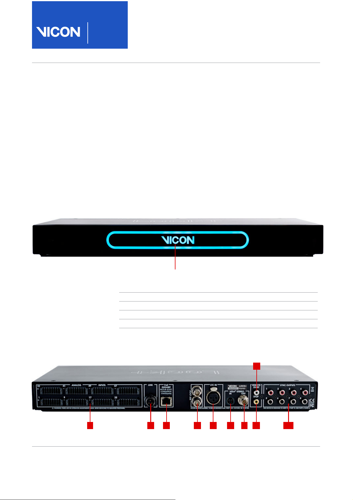
1 2 3 4 5 6 7 8 10
9
Vicon logo illuminates to indicate status:
Color Status
Red Booting
Green Booted but not connected
Blue Communicating with software
Cyan Lock+ selected in software
Quick Start
Guide
Introducing Lock+
Lock+ is a connectivity device from Vicon,
offering a cost-effective and silent solution for
providing synchronization and timecode to your
Vicon Vantage and Vicon Vue cameras.
Lock+ features:
▌ Timecode and genlock
▌ Support of VESA standards
▌ Connection to third-party analog devices
▌ Remotely triggered start and stop
▌ General Purpose Input and Output (GPIO) sockets for
synchronizing external devices
Lock+ front view
Lock+ rear view
Page 2 of 8 March 2018
Page 3

Connections
1 Analog inputs:
8 x connectors, 64 channels
2 Link input/output (I/O)
3 PoE
4 Broadcast sync input (Genlock)
including VITC
5 Timecode input: LTC
6 VESA sync input
7 VESA sync output (reserved for
future use)
8 Remote Control input stop
9 Remote Control input start
10 GPO sync outputs (x8)
Connection details
The rear panel contains the
following sockets for capture and
synchronization (from left to right
of the unit):
1 Analog inputs. Require the
supplied Weidmüller
connectors, with total analog
sample rate of 192 KHz. Enables
you to connect supported thirdparty analog devices. For
instructions on using the
connectors, see Connecting
analog devices on page 4.
Lock+ provides 64 channels for
generating 16-bit offset binary
conversions from analog
sources. The input impedance
Ω. The data sampling
is 1 M
frequency is common to all
channels; you can set the
sampling rate to be a multiple of
the camera base rate up to
192,000 samples/second (192
KHz). The capture frequency
you can specify depends on the
total number of channels to be
sampled, as shown in the
following table:
Number of
channels
1192
296
448
824
16 12
32 6
64 3
2 Link I/O. Provided for Lock+ to
Lock+ synchronization. Also
provides Lock+ to legacy
Giganet synchronization. For
connection to Vicon equipment
only.
3 PoE (conforms to IEEE
802.3af). Requires connection
to a Gigabit (Ethernet
1000BASE-T) PoE router. Use
only the supplied cable.
4 Broadcast sync input (genlock),
including VITC. Dual BNC
sockets for connecting an
external video source that
transmits a composite video
signal, including Vertical
Interval Timecode (VITC), from
the master video source to the
Lock+ and any other
synchronized video or audio
devices in a chain. The Lock+
must be genlocked to this
external video source.
Important: If the Lock+ is the
last device in the chain, the Ref
Loop connection that is not
being used for signal output
must be terminated in 75
remotely or by using a 75
terminator.
Max frequency
(KHz)
Ω
Ω
5 Timecode input: LTC. XLR
socket for connecting an
external source that transmits
LTC (Longitudinal Interval Time
Code) to the Lock+. Requires an
accompanying synchronized
genlock source.
Note: When locking to HD tri-
sync standards (such as Film,
NTSC Film, and 30 fps), LTC is
required for timecode.
6 VESA sync input. 3-pin mini DIN
socket. Current Vicon software
supports 100Hz and 120Hz.
7 VESA sync output. Reserved for
future use.
8 Remote Control input stop.
Phono socket for connecting a
remote third-party device that
triggers the Vicon camera
system to capture data based
on input signals received. Start
and stop are activated on next
frame boundary. Requires
connection to GND (ground).
9 Remote Control input start. See
8 above.
10 GPO sync outputs. Eight
standard programmable phono
(RCA) sockets for
synchronizing external devices
using General Purpose Output
(GPO) signals. To manage the
synchronization of your
external devices, or to trigger
your external devices based on
Vicon system events, identify
an appropriate GPO
configuration file supplied with
your Vicon application software
or create a GPO file of your own
(for details, see the
Vicon Vantage Reference). In
the Vicon application software,
specify this GPO configuration
file for your external device.
Vicon Motion Systems Page 3 of 8
Page 4
Vicon Lock+
35(6672,16(57:,5(
6/277('6&5(:'5,9(5
)/(;,%/(:,5(
62/,':,5(
386+,1
:,7+)(558/(
386+,1
5(/($6(72/2&.:,5(
7239,(:
3,1
3,1
3,1
3,1
5($59,(:
3,10$5.,1*
Quick Start
Guide
Connecting analog devices
The Weidmüller connectors enable
you to connect third-party devices
for capturing analog data, such as
force plates and accelerometers to
a Lock+.
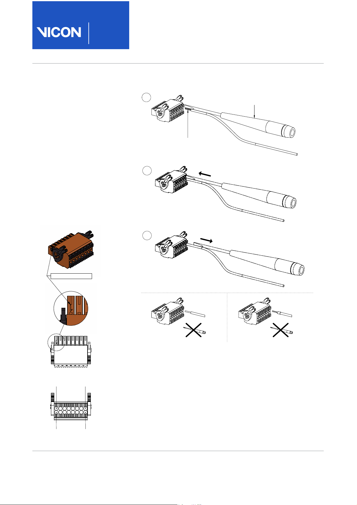
When inserting flexible wire cables
into a connector or extracting them
from a connector, use a slotted
screwdriver as shown in the
illustration (right).
If your cables are rigid (solid wire or
ferrule), you do not need to use a
screwdriver and can push the ends
of the cables into the required
connector.
Pin assignment
The following illustration shows the
pin assignment of the Weidmüller
connectors.
Note that the pins shown in the
illustration (left) are assigned as
follows:
❙ Pins 1–8 (top row): Ground
❙ Pins 9–16 (bottom row): Signal
inputs
In this diagram, the bottom of the
image represents the wire side of
the connector.
Tip: For each socket, the duplicate
pin numbers do not correlate with
the analog channel input. That is, on
connector one (leftmost), pin 9 is
channel 1, pin 16 is channel 8. On
connector four (rightmost), pin 9 is
channel 25, pin 16 is channel 32.
Page 4 of 8 March 2018
Page 5
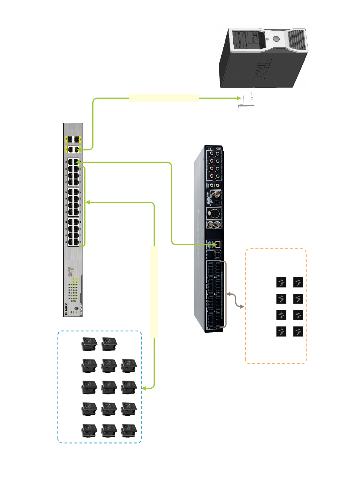
PoE+
Vicon Lock+
Third-party devices
(Up to eight Weidmüller connectors
providing 64 channels)
Network
card
Ethernet cable (1 per camera)
Optical data (Ethernet)
Vantage cameras
(Up to 14 on 26-port PoE+)
Vicon Lock+ in a Vicon Vantage system
Important: PC specification correct at time of publication, but may now be superseded. For the most up-to-date information, search for PC specification on
the Vicon website.
Page 6
Vicon Lock+
Quick Start
Guide
Regulatory information
The following regulatory, safety, and
warranty information is relevant to your
use of Lock+.
❙ Conformity information
❙ Safety information
❙ Warranty information
For information on how to contact
Vicon, see Contact Vicon on page 8.
Conformity information
Federal Communications Commission (FCC) Part 15 information for United States of America customers
This equipment has been
tested and found to comply
with the limits for a Class A
digital device, pursuant to
Part 15 of the FCC Rules
(CFR 47:Part 15:B:2013). These limits
are designed to provide reasonable
protection against harmful interference
when the equipment is operated in a
commercial environment. This
equipment generates, uses, and can
radiate radio frequency energy and, if
not installed and used in accordance
with the instruction manual, may cause
harmful interference to radio
communications. Operation of this
equipment in a residential area is likely
to cause harmful interference, in which
case the user will be required to correct
the interference at his own expense.
Properly shielded and grounded cables
and connectors must be used in order to
meet FCC emission limits. Vicon Motion
Systems Ltd is not responsible for any
radio or television interference caused
by using other than recommended
cables and connectors or by
unauthorized changes or modifications
to this equipment. Unauthorized
changes or modifications could void the
user's authority to operate the
equipment.
This device complies with Part 15 of the
FCC rules. Operation is subject to the
following two conditions: (1) this device
may not cause harmful interference, and
(2) this device must accept any
interference received, including
interference that may cause undesired
operation.
Canadian Interference-Causing Equipment Regulations for Canadian customers
Conformity to the Canadian
Interference-Causing Equipment
Regulations
This Class A digital apparatus meets the
requirements of the Canadian
Interference-Causing Equipment
Regulations ICES-003:2004.
Avis de conformité à la
réglementation d'Industrie Canada
Cet appareil numérique de la classe A
respecte toutes les exigences du
Règlement sur le matériel brouilleur du
Canada ICES-003:2004.
RoHS and RoHS2 information for European Union customers
Restriction of the Use of certain
Hazardous Substances in Electrical
and Electronic Equipment – RoHS
and Recast (RoHS 2)
This equipment is fully RoHS (2002/95/
EC provides that new electrical and
electronic equipment put on the market
for the first time from 1 July 2006) and
RoHS 2-compliant. The European Union
Directive 2011/65/EU provides that new
electrical and electronic equipment put
on the market for the first time from 3rd
January 2014 shall not contain more
than permitted levels of lead, cadmium,
mercury, hexavalent chromium,
polybrominated biphenyls (PBB), or
polybrominated diphenyl ethers
(PBDE;PentaBDE, OctaBDE; DecaBDE),
Mercury (Hg).
REACH Declaration of Conformity
Vicon Motion Systems Ltd is a
manufacturer of electronic hardware.
We are therefore considered a
“downstream user” as far as the REACH
document is concerned. Vicon Motion
Systems Ltd is therefore not obligated to
register with the European Agency for
Chemicals ‘ECHA’.
Products sold by Vicon Motion Systems
Ltd are “articles” as defined in REACH
(Article 3 Definitions). Moreover and
under normal and reasonably
foreseeable circumstances of
application, the articles supplied shall
not release any substance. For that
reason, Vicon Motion Systems Ltd is
neither obligatory for registration nor for
the creation of material safety data
sheets.
To assure our customers of the
continual supply of reliable and safe
products, we ensure that our suppliers
fulfill all requirements regarding
chemical substances and prepared
materials.
Page 6 of 8 March 2018
8
Page 7

Waste Electrical and Electronic Equipment (WEEE) (applicable in the European Union and other European countries with separate collection systems)
The use of the symbol as a
marking on the equipment,
accessories or literature
indicates that this product
and its electronic accessories
(e.g. USB cable) may not be treated as
household waste. By ensuring this
product is disposed of correctly, you will
help prevent potential negative
consequences for the environment and
human health, which could otherwise be
caused by inappropriate waste handling
of this product.
Household users should contact either
their retailer where they purchased this
device, or their local government office,
for details of where and how they can
take these items for environmentally
safe recycling.
Business users should contact their
supplier and check the terms and
conditions of the purchasing contract.
This device and its electronic
accessories should not be mixed with
other commercial waste for disposal.
EU Declaration of Conformity
0088 Medical Devices
Directive 93/42/EEC as
amended by EU Council Directive
2007/47/EC of 5th September
2007 an
Compatibility to EMC Directive
2014/30/EU
We, Vicon Motion Systems Limited
Unit 6,Oxford Industrial Park, Yarnton,
Oxford, OX5 1Q, United Kingdom
Declare that the VICON SAT Interfaces
(supplied as Lock and Lock+)
manufactured by VICON MOTION
SYSTEMS LIMITED meets ANNEX V and
VII Section 5 of the Medical Devices
Directive 93/42/EEC in that the Quality
Management System has been
approved by Lloyd’s Register Quality
Assurance, a notified body of the
European Union (Reg No. 0088) for the
manufacture and support of the
aforementioned CLASS 1(m) Medical
device. Product configurations and
software options below detail the
product configurations and software
d Electromagnetic
options that conform to the metrological requirements of the Directive.
This declaration of conformity is issued
under the sole responsibility of the
manufacturer.
VICON MOTION SYSTEMS LIMITED has
tested and demonstrated that all
products of its own manufacture meet
2014/30/EU:
Electromagnetic Compatibility to:
EN60601-1-2:2007
General Requirements for Safety to:
EN60601-1:2006 + A1:2013
Thomas Shannon TD PhD FIE (Aust)
CPEng (Biomed.)
Director of Compliance
22 February 2018
Not for use in an operating theatre
anaesthetic gas or oxygen-rich
environments. Not for use where there is
a risk of compromising the essential
performance of medical electrical
equipment. Not suitable for use in high
magnetic flux, ionising radiation, sterile,
or life- or safety-critical environments.
Product configurations and software options
Conformity of the Metrological
Performance of CLASS 1 Products
Manufactured in Accordance with
Annex VII, Section 5 of the Medical
Devices Directive 93/42/EEC of the 14th
June 1993.
We, Vicon Motion Systems Limited
Unit 6 Oxford Industrial Park, Yarnton,
Oxford, OX5 1Q, United Kingdom
declare that the VICON SAT Interface
(supplied as Lock and Lock +)
manufactured by VICON MOTION
SYSTEMS LIMITED has been tested prior
to shipment and meets the following
metrological performance:
Measurement Criteria
Supporting software: Blade 3.2 or later,
Nexus 2.2 or later, Tracker 3.1 or later.
Analogue Digital Conversion
Resolution to ± 10 mV mean and ± 10 mV
(1 Standard Deviation).
Synchronization
Difference within one video frame.
Safety information
The following guidance helps you to
ensure the safe operation of your Vicon
system, including the use of Lock+.
To avoid introducing a safety hazard and
possibly damaging the system, please
ensure that an adequate and goodquality alternating current (AC) power
source is available.
For guidance, see the ratings statement
on the rear of the connected PoE or
PoE+ unit. Also ensure that any
computers and peripheral devices are
set to be electrically rated to operate
with the AC power available in your
location.
When working with Vicon systems,
observe the following safety
precautions:
❙ To prevent electric shock, plug all
system components into properly
grounded power sources. These
cables must be equipped with threeprong plugs to ensure proper
grounding. Do not use adapter plugs
or remove the grounding prong from
a cable.
❙ Ensure nothing rests on the system
cables and that cables are not
located where they can be stepped
on or tripped over.
❙ Do not spill food or liquids onto any
electrical component of the system. If
any component gets wet,
immediately contact Vicon Motion
Systems or your nearest agent or
distributor for advice.
❙ Do not push any objects into the slots
of any unit of the system. Doing so
can cause fire or electric shock by
shorting out internal components.
❙ Keep all system components away
from radiators and heat sources, and
do not block cooling vents. Avoid
placing loose papers underneath any
components. Do not place any
components on closed-in units or on
a bed, chair, etc.
❙ Replace fuses with the same type and
rating for continued fire protection.
❙ Do not use outside, near water, in an
environment exposed to anesthetic
or other explosive gases, or in mobile
applications.
Vicon Motion Systems Page 7 of 8
Page 8

Vicon Lock+
Quick Start
Guide
Warranty information
The warranty for your Vicon system
begins after installation. For full details
on warranty scope and conditions, refer
to the Vicon Terms and Conditions of
Supply for your Vicon system.
Contact Vicon
youtube.com/vicon100
facebook.com/vicon
twitter.com/vicon
instagram.com/viconmocap
linkedin.com/company/vicon
vicon.com/products/vicondevices/lock-sync-box
Denver, CO
T:303.799.8686
Los Angeles, CA
T:310.437.4499
Parts list
❙ Lock+
❙ Ethernet cable
❙ Weidmüller connectors
x 8
❙ Rack mount lugs x 2
Oxford, UK
T:+44.1865.261800
© Copyright 2015–2018 Vicon Motion Systems Limited. All rights reserved.
Quick Start Guide — Revision 3.0 March 2018
For use with Vicon Lock+ 1.0
Vicon Motion Systems Limited reserves the right to make changes to information in this documen t without notice. Companies, names, and data used in examples are fictitious
unless otherwise noted. No part of this publication may be reproduced, stored in a retrieval system, or transmitted in any form or by any means, electronic or mechanical, by
photocopying or recording, or otherwise without the prior written permission of Vicon Motion Systems Ltd.
Vicon® is a registered trademark of Oxford Metrics plc. Vicon Blade™, Vicon Bonita™, Vicon Lock+™, Vicon Nexus™, Vicon Tracker™, Vicon Vantage™, Vicon Vero™ aand
Vicon Vue™ are trademarks of Oxford Metrics plc.
VESA® is a registered trademark owned by VESA (www.vesa.org/about-vesa/).
Portions of the software were initially developed by Lucent Technologies Inc., and are subject to the terms of Lucent Public License Version 1.02 (http://plan9.bell-labs.com/
plan9/license.html). All software distributed under such Agreement is distributed on an "AS IS" basis, WITHOUT WARRANTY OF ANY KIND, either express or implied. See the
Lucent Public License for the specific language governing all rights, obligations and limitations under such Agreement.
Portions of the software developed by Lucent Technologies Inc. are Copyright © 1999–2003. All rights reserved.
Contributor: Vicon Motion Systems Ltd.
Part of the software embedded in this product is eCos (Embedded Configurable Operating System), a registered trademark of eCosCentric Limited. eCos is released under a
modified version of the GNU General Public License (GPL) (http://ecos.sourceware.org/license-overview.html) Co pyright © 2007 Free Software Foundation, Inc. (www.fsf.org).
Other product and company names herein may be the trademarks of their respective owners.
Vicon Motion Systems is an OMG plc company.
Email: [email protected] Web: www.vicon.com
Page 8 of 8 March 2018
8
 Loading...