

Page 1

Operating Instructions
Stud Welding Pistol
PS-1
PS-3K
PS-0K
PS-1K
R
Page 2

R
Operating Instructions
Stud Welding Pistol
PS-1
PS-3K
PS-0K
PS-1K
Serial number*
Stud Welding Pistol PS-1
Serial number*
Stud Welding Pistol PS-3K
Serial number*
Stud Welding Pistol PS-0K
Serial number*
Stud Welding Pistol PS-1K
* Please mark your Stud Welding Pistol type here and enter the serial number so that
these are available if you require service support.
Heinz Soyer Bolzenschweißtechnik GmbH
Etterschlag
Inninger Straße 14
82237 Wörthsee
Phone 08153 - 885 - 0
Telefax 08153 - 8030
Telex 5270 295 heso d
Page 3

R
Date of issue: Dec. 1, 1994
SOYER is a registered trademark of Heinz Soyer Bolzenschweißtechnik
GmbH.
It is prohibited to convey or reproduce this document, as well as to utilise or disclose its contents, unless this has
been explicitly authorised.
In the event of noncompliance with this regulation, damages will be charged. All rights reserved, in particular in the
event of patent grant or GM registration.
This is to certify that we have verified the contents of this publication which comply with the hard- and software
described. Deviations, however, cannot be excluded, so that we cannot warrant for absolute compliance. The
specifications in this documentation have been verified regularly and necessary corrections incorporated into the
following versions. We appreciate any suggestions for improvement.
Heinz Soyer Bolzenschweißtechnik GmbH 1994 · All rights reserved
Subject to technical modifications.
Printed in the Federal Republic of Germany.
Page 4
R
Page 5

R
Table of Contents
Table of Contents
1. General information ________________________________________________ 1-1
1.1 The following should be principally observed ..______________________________1-1
1.2 Intended use __________________________________________________________1-2
1.3 Information on the product ______________________________________________1-2
1.4 Serial number _________________________________________________________1-2
1.5 Information on the documentation ________________________________________1-3
1.5.1 Chapters of Operating Instructions________________________________________1-3
1.5.2 Information on the Operating Instructions __________________________________1-4
1.5.3 Reaction in the case of malfunctions ______________________________________1-4
1.6 Contacts and service adress_____________________________________________1-4
2. Description of the Stud Welding Pistols _____________________________ 2-5
2.1 Technology of tip ignition ________________________________________________2-5
2.2 Stud Welding Pistol PS-1________________________________________________2-6
2.3 Stud Welding Pistol PS-3K ______________________________________________2-7
2.4 Stud Welding Pistol PS-0K ______________________________________________2-8
2.5 Stud Welding Pistol PS-1K ______________________________________________2-9
2.6 Technical data ________________________________________________________2-10
3. Safety instructions ________________________________________________ 3-11
3.1 Characterisation of references in the Operating Instructions__________________3-11
3.2 Staff qualification and training ___________________________________________3-12
3.3 Dangers resulting from non-observance of safety instructions ________________3-12
3.4 Safety-conscious working ______________________________________________3-12
3.5 Safety instructions for the User/Operator__________________________________3-13
3.6 The following should be observed prior to initialisation ... ____________________3-13
3.7 Before starting welding operations ..._____________________________________3-14
3.8 Safety measures at the installation site ___________________________________3-14
3.9 Working with the Stud Welder___________________________________________3-15
3.10 Safety instructions for maintenance, inspection and assembly operations ______3-15
3.11 Independent retrofitting and spare parts production ________________________3-15
3.12 Non-permissible operating modes _______________________________________3-16
i
Page 6

R
Table of Contents
4. Setting the Stud Welding Pistol ____________________________________ 4-17
4.1 Setting the stud holder_________________________________________________4-17
4.2 Installing the stud holder in the Stud Welding Pistol_________________________4-18
4.3 Setting the spring pressure _____________________________________________4-19
5. Initiation __________________________________________________________ 5-20
5.1 General view _________________________________________________________5-20
5.2 Connecting the Stud Welding Pistols to the Stud Welder ____________________5-21
5.3 Operation ____________________________________________________________5-21
5.4 Welding parameters ___________________________________________________5-22
5.4.1 Stud Welder BMS-660-90______________________________________________5-22
5.4.2 Stud Welder BMS-690-135_____________________________________________5-22
5.4.3 Stud Welder BMS-6H__________________________________________________5-23
5.4.4 Stud Welder BMS-8H__________________________________________________5-23
6. Quality control_____________________________________________________ 6-24
6.1 General information ___________________________________________________6-24
6.2 Demands on the company _____________________________________________6-24
6.3 Proof of qualification ___________________________________________________6-24
6.4 Type and scope of testing ______________________________________________6-24
6.4.1 Normal work tests_____________________________________________________6-25
6.4.2 Simplified work tests___________________________________________________6-25
6.5 Implementation of sample taking ________________________________________6-25
6.5.1 Production of samples _________________________________________________6-25
6.5.2 Visual check _________________________________________________________6-25
6.5.3 Tension test __________________________________________________________6-26
6.5.4 Bending test _________________________________________________________6-26
7. Maintenance ______________________________________________________ 7-27
7.1 Stud welders _________________________________________________________7-27
7.2 Replacing components ________________________________________________7-27
ii
Page 7

R
Table of Contents
8. Spare parts________________________________________________________ 8-28
8.1 Spare parts list Stud Welding Pistol PS-1 _________________________________8-28
8.2 Perspective presentation of Stud Welding Pistol PS-1_______________________8-29
8.3 Spare parts list Stud Welding Pistol PS-3K ________________________________8-30
8.4 Perspective presentation of Stud Welding Pistol PS-3K _____________________8-31
8.5 Spare parts list Stud Welding Pistol PS-0K ________________________________8-32
8.6 Perspective presentation of Stud Welding Pistol PS-0K _____________________8-33
8.7 Spare parts list Stud Welding Pistol PS-1K ________________________________8-34
8.8 Perspective presentation of Stud Welding Pistol PS-1K _____________________8-35
9. Troubleshooting ___________________________________________________ 9-36
10. Standards and list of directives _______________________________ 10/11-38
11. Warranty terms_______________________________________________ 10/11-38
iii
Page 8

R
1 General information
1.1 The following should be principally observed ...
With this Stud Welding Pistol you have purchased a product which
• corresponds to the latest state-of-the-art in technology
• complies fully to the present-day safety standards and
• enables successful operating.
Please observe the following points in any case before installing the Stud
Welding Pistol:
• Store the Operating Instructions in a place to which every Operator has
access.
• Ensure that the respective Operator has read and understood the Operating
Instructions before installation. Each Operator should sign a written
confirmation to certify this.
• Prevent use of Stud Welder by unauthorised personnel.
• An electronics technician should check whether the electric supply is
properly protected by fuse and earthed.
• Only trained personnel may use the Stud Welding Pistol.
General information
MORTAL DANGER
Persons with cardiac pacemakers must not operate the Stud Welder and
must keep away from a Stud Welder during operation. Ensure in particular
that the Stud Welding System is not operated near electronically sensitive
life-saving equipment, as in intensive wards in hospitals.
WARNING
Ensure that sufficient distance to electronic equipment is kept. Highly
intensive electro-magnetic fields are created in stud welding which may
permanently damage these devices (e.g. television sets).
• Furthermore, observe the safety instructions stated in Chapter 3.
• Call a doctor in the event of an accident.
MORTAL DANGER
The S-symbol is the symbol for welding current sources permitted
for operation with increased electric danger. The S-symbol on our stud
welders refers exclusively to the welding current circuit and not to the
complete stud welder.
1-1
Page 9

General information
1.2 Intended use
R
With the SOYER® Stud Welding Pistols PS-1, PS-3K, PS-0K and PS-1K
operating with tip ignition, a variety of pins and threaded bolts of steel and
stainless steel can be welded (dimensions see Chapter 2.6: “Technical data”).
It is also possible to weld fastening elements of brass. The Stud Welding Pistol
PS-1 is also suitable for welding aluminium.
The visible side of the workpieces remain to a large extent unaffected by tool
drag marks or deformation, so that if thin metal sheets of below 1mm sheet
thickness are welded, a decorative appearance will be maintained.
Please contact either our parent company or one of our field engineers if you
require consultation or a solution to your problem.
1.3 Information on the product
Manufacturer Heinz Soyer Bolzenschweißtechnik GmbH
Product designation Stud Welding Pistol PS-1
Country of origin Germany
1.4 Serial number
The serial numbers of the Stud Welding Pistols are engraved into the handle.
Etterschlag
Inninger Straße 14
D-82237 Wörthsee
Phone 08153-885-0
Telefax 08153-8030
Telex 52700295 heso d
Stud Welding Pistol PS-3K
Stud Welding Pistol PS-0K
Stud Welding Pistol PS-1K
1-2
Page 10

R
1.5 Information on the documentation
The following Operating Instructions are delivered with the Stud Welding Pistols
PS-1, PS-3K, PS-0K and PS-1K:
•
Operating Instructions “Stud Welding Pistol PS-1, PS-3K, PS-0K and PS-1K”
Order No.: P00277
For subsequent orders please refer to:
Heinz Soyer Bolzenschweißtechnik GmbH
Etterschlag
Inninger Straße 14
D-82237 Wörthsee
Phone 08153-885-0
Telefax 08153-8030
Telex 52700295 heso d
General information
1.5.1 Chapters of Operating Instructions
The Operating Instructions describe how to handle and set the Stud Welding
Pistols under normal conditions and comprise the following individual chapters:
• Chapter 1 “General Information”
Information on application, the product and supplementary information
• Chapter 2: “Description of Stud Welding Pistols”
Description of tip ignition technology and of the Stud Welding Pistols
• Chapter 3 “Safety instructions”
All relevant safety regulations regarding initiation and operation of the Stud
Welding System
• Chapter 4 “Setting the Stud Welding Pistol”
• Chapter 5 “Initiation”
• Chapter 6 “Quality Control”
• Chapter 7 “Maintenance”
Maintenance measures
• Chapter 8 “Spare parts”
• Chapter 9 “Troubleshooting”
Error characteristics, possible causes and elimination of errors
• Chapter 10 “Standards and list of directives”
• Chapter 11 “Warranty terms”
1-3
Page 11

General information
1.5.2 Information on Operating Instructions
Legal relationship We draw attention to the fact that the contents of these Operating Instructions
are neither part of any former or existing agreement, promise or legal
relationship nor are designed to modify any such. All obligations of Heinz Soyer
Bolzenschweißtechnik GmbH result from the respective purchase agreement
containing the complete and generally valid warranties. These contractual
warranty terms are neither extended nor limited by the implementation of these
Operating Instructions.
WARNING
It is prohibited to carry out any actions on the Stud Welding System without
having exact knowledge of the Operating Instructions or of the respective
part. Ensure that only qualified personnel familiar with the Operating
Instructions and the necessary technical activities (training) is permitted to
operate the Stud Welding System.
R
1.5.3 Reaction in the case of malfunctions
If faults occur, first try to determine and eliminate the error causes according to
the error characteristics listed in the Operating Instructions in Chapter 12
“Troubleshooting”. In all other cases, contact our service department.
Important information If you require service, please ensure that the following information is available:
if service is required
• Customer number
• Product designation
• Serial number
• Construction year
• Options
• Stud and workpiece material
• Stud diameters
This information will help us and you to save time and unnecessary costs, e.g.
for false spare parts deliveries.
1.6 Contact and service address
1-4
If you have any questions relating to the operation of your Stud Welding
System, retrofits or in any service case, please contact your responsible
service office or the following address:
Heinz Soyer Bolzenschweißtechnik GmbH
Etterschlag
Inninger Straße 14
D-82237 Wörthsee
Phone 08153-885-0
Telefax 08153-8030
Telex 52700295 heso d
Page 12
R
Description of the Stud Welding Pistols
2 Description of the Stud Welding Pistols
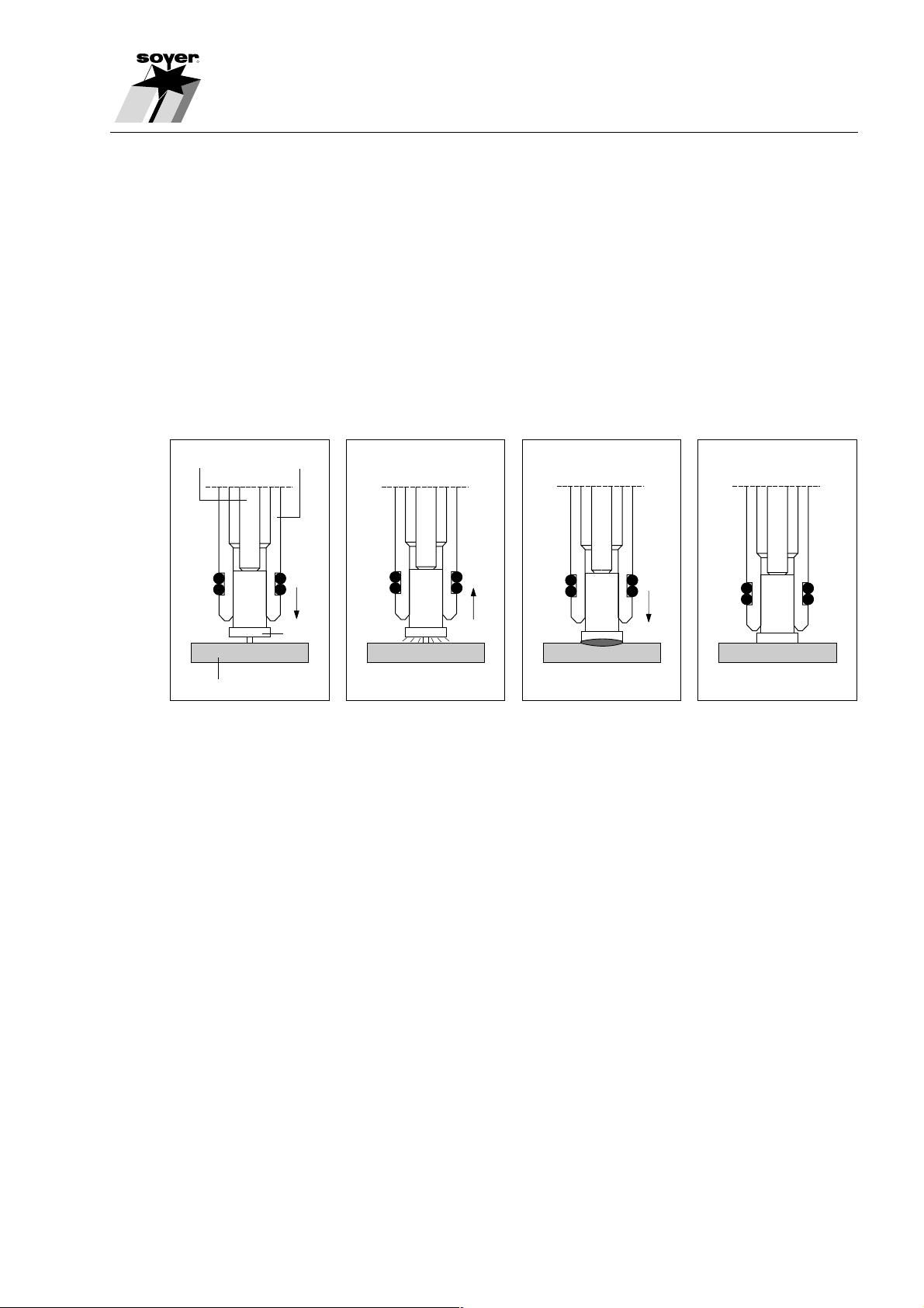
2.1 Technology of tip ignition
The SOYER® Stud Welding Systems function according to the principle of
capacitor discharge with tip ignition in compliance with DVS leaflet 0903
(German Welding Society).
This system utilises the abrupt discharge of a capacitor battery to generate
electric arc energy.
Adjusting screw Stud holder
Workpiece
Stud
SZ.0001.E
The electric arc is initiated via the calibrated and close fit ignition tip on the
welding studs and the welding elements. The stud weld base and the opposite
surface of the workpieces is then melted slightly. The stud is automatically
immersed into the thin melted zone and/or the liquid weld bath. After the
immediate solidification of the material, an homogenous high-strength joint in
an extremely short welding time ranging only between 1-3 milliseconds (0.001-
0.003 sec.) is achieved.
2-5
Page 13
Description of the Stud Welder Pistols
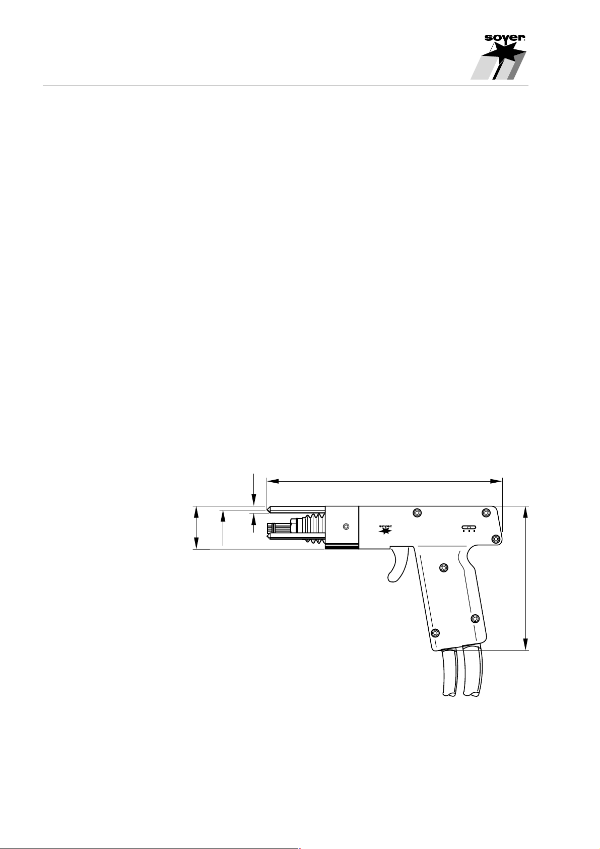
2.2 Stud Welding Pistol PS-1
The SOYER® Stud Welding Pistol PS-1 is designed for a wide variety of
applications. The field-proven patented Positioning Pistol has a handy design,
is lightweight and is injection moulded of shock-proof, fully insulated plastic.
With this pistol the welding stud can be positioned exactly on a specific part of
the workpiece without requiring any auxiliary aids. Templates are not required.
Before welding the stud position has to be marked or centred slightly. The
calibrated ignition tip is then positioned on the marked point. When the pistol is
operated, the stud is mechanically lifted. A necessary air gap is created
between the tip and the workpiece. The stud is then mechanically moved to
the marked point and is welded with electric arc ignition as soon as the marked
point is reached.
R
The pistol guide is protected by rubber bellows especially against weld spatters
and dirt.
A special spring pressure display with scale shows the spring pressure for the
respective welding task and enables the reproducibility of welding joints, if
necessary.
.
211
Ø 6
Federdruck
321
Ø 40
Ø 34
R
Bolzenschweißer
Typ PS-1
3x120°
132
2-6
SZ05.0693.005.D
Page 14
R
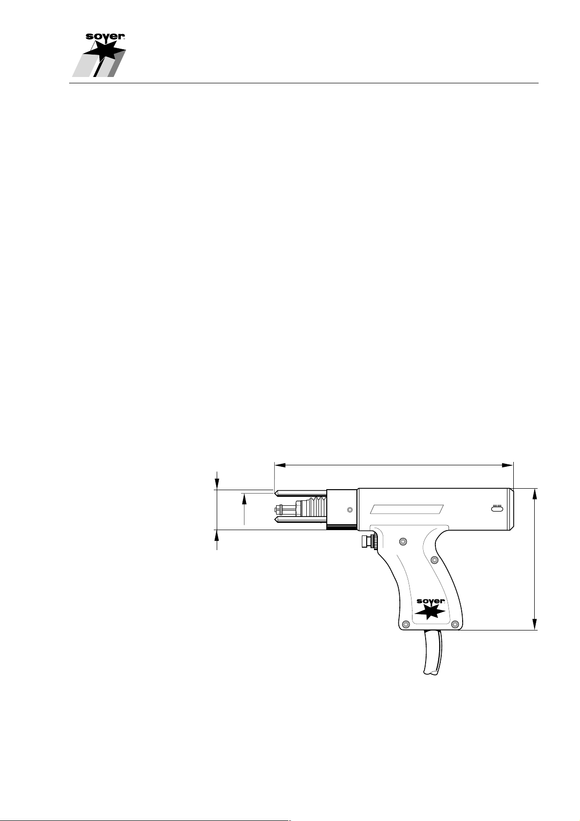
2.3 Stud Welding Pistol PS-3K
The SOYER® Stud Welding Positioning Pistol PS-3K for stud welding with tip
ignition welds studs with ignition tip in accordance with DIN 32501 to exact
positions on scribed surfaces or centre marks by means of spring pressure
without any auxiliary aids. It is particularly suitable for stud welding to
workpieces and materials with impure surfaces, such as zinc, rolling skin,
forging scales and oxide films.
The Stud Welding Pistol PS-3K functions without backstroke and prevents a
dislocation during the welding procedure. It is suitable for all stud welding
systems with tip ignition.
It is equipped with a sturdy, shock and break-proof whole-body housing in a
small and light-weight version. This closed pistol design guarantees additional
stability and solidity advantages in contrast to the semimonocoque design.
Description of the Stud Welding Pistols
With the modular concept it is possible to retrofit the pistol to other stud
welding systems using existing mechanical sets.
The Stud Welding Pistol PS-3K corresponds to the latest state-of-the-art in
technology and fits like a glove similar to all other SOYER Stud Welding Pistols
thanks to its excellent ergonomic design.
235
ø 40
ø 34
3x120°
PS-3K
R
138
SZ06.0593.003.X
2-7
Page 15

Description of the Stud Welder Pistols
2.4 Stud Welding Pistol PS-0K
The SOYER® Stud Welding Positioning Pistol PS-0K is an innovation and
unique on the world market due to its small dimensions.
It is suitable for contact welding in accordance with the tip ignition welding
method for studs and pins of steel and special steel and was developed in
particular for stud welding in narrow or hardly accessible spaces or on
complicated workpieces.
Despite its small dimensions perfect welding results are nevertheless
achievable with the Stud Welding Pistol PS-0K which can be compared with
the welding qualities created with larger manual welding pistols.
This Stud Welding Pistol can be easily connected to all thyristor-driven stud
welding equipment in accordance with the tip ignition principle.
R
75
PS - OM
100
R
2-8
Display scale 1:1
SZ05.0594.014.X
Page 16

R
2.5 Stud Welding Pistol PS-1K
The SOYER® Stud Welding Positioning Pistol PS-1K for stud welding with tip
ignition is a shortened version of Stud Welding Pistol PS-3K (see Chapter 2.3).
It welds studs with ignition tips in accordance with DIN 32501 exactly on
scribed surfaces or centre marks by means of spring pressure without any
auxiliary aids. It is particularly suitable for stud welding on workpieces and
materials with impure surfaces, such as zinc, rolling skin, forging scales and
oxide films, similar to the Stud Welding Pistol PS-3K. It is designed for
application in narrow and hardly accessible spaces due to its compact
construction.
The Stud Welding Pistol PS-1K functions without backstroke and prevents a
dislocation during the welding procedure. It is suitable for all stud welding
systems with tip ignition.
Description of the Stud Welding Pistols
It is equipped with a sturdy, shock and break-proof whole-body housing in a
small and light-weight version. This closed pistol design guarantees additional
stability and solidity advantages in contrast to the semimonocoque design.
The Stud Welding Pistol PS-1K corresponds to the latest state-of-the-art in
technology and fits like a glove similar to all other SOYER Stud Welding Pistols
thanks to its excellent ergonomic design.
124
ø 30
PS - 1K
140
R
SZ05.0594.015.X
2-9
Page 17

Description of the Stud Welder Pistols
2.6 Technical data
Welding range
- Threaded bolts M3 - M8 M3 - M10 M3 - M8 M3 - M8
- Studs Ø 2 - 8 mm Ø 2 - 10 mm Ø 3 - 8 mm Ø 3 - 8mm
R
PS-1 PS-3K PS-0K PS-1K
Field of application
1* 2* 2* 3*
Welding system Tip ignition in accordance with DVS Leaflet 0903
Welding and
control cable 3 m highly flexible
Weight
without cable 0.5 Kg 0.9 kg 0.3 kg 0.4 kg
1* Steel, stainless steel, aluminium and brass
2* Steel and stainless steel
3* Steel, stainless steel and brass
2-10
Page 18

R
Safety instructions
3 Safety instructions
These Operating Instructions contain fundamental instructions which have to
be observed in installation and/or operation. These Operating Instructions
therefore have to be read by the Operator and the responsible technical
personnel prior to assembly and initiation. They must furthermore be constantly
available at the installation site.
Not only the general “Safety Instructions” listed under this main item, but also
the special safety instructions e.g. for high temperatures, voltages etc. stated
under other main items have to be observed.
3.1 Characterisation of references in the Operating Instructions
The safety instructions which may cause damage to persons in the case of
non-observance, are specially characterised with the general danger symbol,
safety instructions in accordance with DIN 4844-W9,
warning of electric voltage with the
safety symbol in accordance with DIN 4844-W8.
3-11
Page 19

Safety instructions
The word ACHTUNG (CAUTION) or WARNUNG (WARNING) has been
incorporated into safety references the non-observance of which may lead to
dangers for the machine and its functions.
General instructions are characterised with the following symbol:
3.2 Staff qualification and training
The staff designated for operation, maintenance, inspection and assembly
must fulfil the qualifications required for these operations. Field of responsibility,
competence and control of staff must be exactly regulated by the user. If the
staff do not possess the qualifications required, these must be provided with
the necessary training and instructions. This can, if necessary, be implemented
by the manufacturer/supplier on behalf of the user. Furthermore, the user shall
ensure that the contents of the Operating Instructions are fully understood by
the personnel.
R
☞
The Schweißtechnische Lehr- und Versuchsanstalt München (SLV) (Training
and Testing Institute of Welding) offers appropriate training courses.
3.3 Dangers resulting from non-observance of safety instructions
Non-observance of safety instructions may not only represent danger to
persons, but also to the welding system and the environment. If the safety
instructions are not observed, this may lead to a complete loss of warranty
claims.
Non-observance may for example lead to the following individual dangers:
• Failure of important functions of the system
• Failure of prescribed methods for maintenance and repair
• Danger to persons by electric, mechanic, thermal and acoustic influences
3.4 Safety-conscious working
The safety instructions stipulated in these Operating Instructions, the existing
national regulations governing accident prevention, as well as possible international work, operating and safety regulations of the Operator must be
observed.
3-12
Page 20

R
3.5 Safety instructions for the User/Operator
In stud welding dangers may arise as a result of
• electric current
• optical radiation
• harmful substances (fumes)
• acoustic shocks
• spraying sparks
You are therefore obliged to limit the dangers to an unavoidable minimum and
to inform the Operator and other persons of such dangers.
Safety instructions
MORTAL DANGER
Persons with cardiac pacemakers must not operate the Stud Welder and
must keep away from Stud Welders in operation.
3.6 The following should be observed prior to initiation...
Before initiating the system, the following points must be observed:
• The Stud Welding System must not be operated by juveniles below 16 years
of age
• Read through the complete Operating Instructions before initiating the
system
• Only qualified personnel is authorised to operate the system
• Prevent unauthorised use of the system by children or by unqualified
personnel
• Wear non-combustible, closed working clothes
• Wear a leather apron over your work dress. Weld spatters are generated
during the welding operation
• Wear a helmet when carrying out welding operations above your head
DANGER
Do not weld with work dress which is soiled with easily combustible
substances such as oil, grease, paraffin oil etc.
3-13
Page 21

Safety instructions
• Wear leather gloves with sleeves
• Wear neither rings, watches nor electrically conducting jewellery
• Wear protective goggles with eye-protecting lens of shade number 2. (DIN
58211, part 6). Weld spatters and light flashes are generated during welding
operations.
• Wear protective goggles with side shields when removing slag
• Wear ear protection. A loud acoustic shock is generated when discharging
the capacitors.
3.7 Before starting welding operations ...
R
• Verify the state of all cables before starting a welding operation
• Immediately replace any faulty cables and cable connections
• Ensure that ventilation openings in the stud welder housing are not covered.
The Stud Welder may otherwise be damaged as a result of heat
accumulation.
3.8 Safety measures at the installation site
• Ensure when installing the Stud Welder on tables or similar workshop
furniture that the Stud Welder is positioned firmly and that the table or
appropriate furniture can bear the appropriate load.
• Ensure that the power socket and the Stud Welder have been connected to
the ground properly
• Observe fire prevention regulations and do not carry out any welding
operations in hazardous locations
• Ensure that the room is ventilated well or if necessary, extract the welding
vapours.
3-14
DANGER TO HEALTH
During welding operations vapours and suspended matters may be
generated. In particular beware of fumes detrimental to health when using
surface-treated materials. If possible only carry out welding operations in
rooms which have a room height exceeding 3 m. Special regulations in
accordance with VBG 15 are applicable for narrow rooms.
Page 22

R
3.9 Working with the Stud Welder
* Observe all accident prevention regulations which are applicable for
operating your Stud Welder
The accident prevention regulation VBG15 “Welding, Cutting and
☞ similar work methods” is applicable for Stud Welders. For more
information contact the employer’s liability insurance association.
MORTAL DANGER
Do not weld with work dress which is soiled with easily combustible
substances such as oil, grease, paraffin oil etc.
Safety instructions
If an accident happens:
• switch off the Stud Welder, disconnect the power supply and
• call a doctor.
3.10 Safety instructions for maintenance, inspection and assembly
operations
Only carry out maintenance The User shall ensure that all maintenance, inspection and assembly
work when the Stud Welder operations are carried out by authorised and qualified technical personnel
has come to a standstill after having sufficiently informed himself by studying the Operating Instructions
carefully.
Principally, operations may only be carried out when the Stud Welder has
come to a standstill. The procedure to bring the Stud Welder to a standstill
described in the Operating Maintenance Instructions must be observed.
Immediately after completing the work, ensure that all safety and protection
features are restored and that these function.
3.11 Independent retrofitting and spare parts production
Retrofitting or modifications of the Stud Welder are only permissible with the
manufacturer’s approval. Original spare parts and authorised accessories are
designed to guarantee safety. The use of any other parts may result in an
annulment of warranty for any damages thus caused.
3-15
Page 23

Safety instructions
3.12 Non-permissible operating modes
Limit values Operational safety of the Stud Welder supplied can only be guaranteed if it is
used in accordance with its purpose. The limit values specified in the
“Technical Data” must not be exceeded under any circumstances.
R
3-16
Page 24

R
4. Setting the Stud Welding Pistol
4.1 Setting the Stud Holder
The stud holders of the Stud Welding Pistols PS-1, PS-3K, PS-0K and PS-1K
have the same construction. If long welding studs are used it is, however, due
to the short construction form of the Stud Welding Pistols PS-0K and PS-1K
necessary to appropriately shorten the stop screw (4) of the stud holders on
these Welding Pistols.
Setting the Stud Welding Pistol
1
1,5
1 Stud 3 Counternut
2 Stud holder 4 Stop screw
If other stud diameters are used, different stud holders matching the stud
diameters are required.
Set the stud holder as follows:
• Loosen counternut (3)
• Insert stud (1) into the stud holder.
The top edge of the stud flange must project over the front edge of the stud
holder by about 1.5 mm.
2
3
SZ06.0593.012.X
4
NOTE
The stud must be inserted until it reaches the stop screw (4).
• Adjust stop screw (4) in the stud holder by rotating movement until the
dimension of 1.5 mm between the top edge of the stud flange and the front
edge of the stud holder is reached.
• Tighten stop screw (4) with the counternut (3).
4-17
Page 25

Setting the Stud Welder Pistol
4.2 Installing the stud holder in the Stud Welding Pistol
The following diagram shows how the stud holder is installed in the Stud
Welding Pistols PS-1 and PS-3K. The Stud Welding Pistols PS-0K and PS-1K
are equipped with a support tube instead of the pistol feet (1).
R
1
23 5
4
6
SZ05.0693.010.X
1 Pistol foot 4 Bellows
2 Stud holder 5 Spring shaft
3 Union nut 6 Stud flange
• Loosen union nut (3) on Stud Welding Pistols PS-1 and PS-3K using the
socket spanner SW 17; for Stud Welding Pistols PS-0K and PS-1K socket
spanner SW 14 is required.
4-18
• Push stud holder (2) into the spring shaft (5) until it stops.
• Fix stud holder (2) into position with union nut (3).
NOTE
The stud flange must project over the pistol feet tips and the support tube
by the dimension of the flange thickness. If necessary, remove stud holder
and correct projection by adjusting the stop screw.
Page 26

R
4.3 Setting the spring pressure
The pressure with which the stud is pressed onto the workpiece during the
welding process is referred to as spring pressure.
The following diagram displays the spring pressure setting for the Stud Welding
Pistol PS-1 with spring pressure display. The Stud Welding Pistol PS-3K is
equipped with a similar spring pressure display. The Stud Welding Pistols PS0K and PS-1K do not display the spring pressure.
Setting the Stud Welding Pistol
1
2
Spring pressure
321
SZ05.0693.011.E
1 Setting screw
2 Spring pressure display
The spring pressure can be set on all Stud Welding Pistols described using the
same setting screw (1). The spring pressure setting is displayed on the spring
pressure scale (2). The spring pressure is set as follows:
• Turn setting screw (1) to the left until it stops
Display position 1 = low pressure
• Turn setting screw (1) by 3.5 rotations to the right
Display position 2 = medium pressure
• Turn setting screw (1) to the right until it stops
Display position 3 = high pressure
The spring pressure setting depends on the quality of the welding stud and of
the workpiece.
Carry out welding samples and tests before starting work to determine an
optimum setting.
Samples should be taken several times during production to ensure that
equally good welding results are achieved throughout the whole production
process (see DVS Directive 0905, part 2 “How to ensure the quality of stud
welding joints”).
4-19
Page 27

Initialisation
5. Initiation
5.1 General view
R
The following diagram displays the Stud Welding Pistol PS-3K. It only differs
slightly from the Stud Welding Pistols PS-1, PS-0K and PS-1K.
* The Stud Welding Pistols PS-0K and PS-1K are equipped with support
tubes instead of the pistol feet (2).
* The Stud Welding Pistols PS-0K and PS-1K are not equipped with a spring
pressure display.
12 3
7
PS-3K
4
6
R
5
SZ05.0594.016.X
1 Union nut 5 Connecting cable
2 Pistol foot 6 Release switch
3 Spring pressure display 7 Stud holder
4 Setting screw for spring
pressure
5-20
Page 28

R
T
T
5.2 Connecting the Stud Welding Pistols to the Stud Welder
The Stud Welding Pistols are connected to the Stud welder using the pistol
and control cables.
Pistol +
ype
Stud Welder
BMS-660-90, BMS-690-135
8 Socket for connecting welding
cable
9 Socket for connecting control
cable
89
Initialisation
ype
Stud Welder
BMS-6H, BMS-8H
10 Socket for connecting welding
cable
11 Socket for connecting control
10 11
cable
SZ.0015.E
• Insert welding cable plug of the Stud Welding Pistol into the welding cable
socket (8/10)
• Insert control cable plug of the Stud Welding Pistol into the control cable
socket (9/11) and lock with spring clip
Observe the connecting instructions in the Operating Instructions for Stud
Welders.
5.3 Operation
• Create ground connection of the Stud Welder
• Connect Stud Welding Pistol as described in Chapter 5.2
• Set Stud Welding Pistol as described in Chapter 4
• Connect Stud Welder to power supply
• Set Stud Welder for the welding studs to be welded
• Insert welding stud into the stud holder
• Position Stud Welding Pistol onto the workpiece and press release switch
5-21
Page 29

Initialisation
5.4 Welding parameters
The following charging voltages specified in the diagram below are standard
values which have been determined in combination with the respective stud
welder and the standard Welding Pistol PS-1. AlMg3 and StVK were used as
stud material, AlMg3 or St. as base material. The charging voltages vary from
the stated setting according to the material type, workpiece thickness and
surface condition of the workpiece.
5.4.1 Stud Welder BMS-660-90
220
R
200
180
160
140
120
100
Charging voltage (V)
80
60
5.4.2 Stud Welder BMS-690-135
220
200
180
M3
M4 M5 M6 M8
Stud diameter
SZ.0011.E
5-22
160
140
120
100
Charging voltage (V)
80
60
M3
M4 M5 M6 M8
Stud diameter
SZ.0012.E
Page 30

R
5.4.3 Stud Welder BMS-6H
Charging voltage (V)
Initialisation
220
200
180
160
140
120
100
80
60
5.4.4 Stud Welder BMS-8H
Charging voltage (V)
220
200
180
160
140
120
100
80
60
M3
M3
M4 M5 M6 M8
Stud diameter
SZ.0013.E
M4 M5 M6 M8
Stud diameter
SZ.0014.E
5-23
Page 31

Quality Control
6 Quality Control
6.1 General information
The DVS directive 0905, part 2 of April 1979 is valid with regard to ensuring the
quality of stud welded joints. The tests described in this section have been
written in a simplified form on the basis of this directive. They refer to work
tests which are carried out and controlled by the User prior to and during
welding works.
Heinz Soyer Bolzenschweißtechnik GmbH is a member of the Deutscher
Verband für Schweißtechnik e.V. (DVS) (German Welding Society), Munich.
6.2 Demands on the company
R
The company must appoint a responsible welding supervisor and employ
appropriately qualified operating personnel for stud welding (see DVS Directive
0905, part 2, section 4).
6.3 Proof of qualification
In the case of components which are subject to documentation requirements
and/or stud welding works which are subject to acceptance in compliance with
DIN 4100, DIN 4113, the manufacturing company must submit proof of
competence or a qualification certificate (see DVS Directive 0905, part 2,
sections 4.1 and 4.2). The competence qualification is applicable in particular
for fastening constructions concerning safety regulations. If the Stud Welder is
used in the construction industry, only permissible base and stud materials
(see e.g. DIN 4100, clause 2.1, registration license for stainless steel ifBT; DIN
4113, part 2) may be applied.
6.4 Type and scope of testing
If the SOYER stud welding system is handled in compliance with regulations
and the proper materials are selected, the welded joint strength (welding zone)
will always be higher than that of the stud or base material. In practical
operation, the following work tests are carried out:
6-24
• Normal work test (see DVS Directive 0905, part 2, section 5.1.2)
• Simplified work test (see DVS Directive 0905, part 2, section 5.1.2)
Page 32

R
6.4.1 Normal work test
Quality Control
Normal work tests are generally to be implemented and controlled by the
Operator prior to carrying out welding works at a construction and after a
certain number of welds. The number of welds after which a normal work test
is necessary is agreed with the customer.
The normal work test is restricted to the stud diameters, base material and
stud welder type used. It includes the following tests:
• Visual check (all samples)
• Tension test (at least 3 samples)
• Bending test (at least 3 samples)
In case of doubt, the scope of testing should be extended in compliance with
the DVS Directive 0905, part 2, section 5.1.1).
6.4.2 Simplified work test
Simplified work tests serve to control the correct stud welder setting and
functioning of the equipment. They are carried out before starting any shift or
after any interruption lasting for several hours.
The simplified work test includes:
• Visual check (all samples)
• Bending test (all samples)
6.5 Implementation of sample taking
6.5.1 Production of samples
The studs for the work test are welded to a sheet metal the minimum size of
which is 700 mm x 200 mm. The same welding positions and distances to the
borders shall be adhered to as on the construction part. Identical parts to
those to be used in later production should be used for the tests provided this
is possible and economically justifiable.
6.5.2 Visual check
The visual check serves as a rough control to detect any possible major faults.
The uniformity of the welding is assessed. Tension or bending tests must be
carried out in case of doubt.
6-25
Page 33

Quality Control
6.5.3 Tension test
R
The tension test serves to test the metallic bond between the stud and the
base material. At least 3 studs are welded and then axially loaded by means of
an appropriate tensile testing machine unitl they break. If the Customer
demands that a certain percentage of the welded studs should be tested with
a predefined test load in production, a tensile testing machine with load unit
display must be used.
If the stud breaks beyond the welding zone, the sample test is regarded as
successful. If the stud breaks within the welding zone, the fracture must be
examined. The unwelded surface must not exceed a maximum of 20% of the
welding surface. In cases of doubt, the breaking load is to be examined in
accordance with DIN 267, part 3.
If the number of faulty studs in any one random test exceeds the acceptance
number in compliance with DIN 267, part 5, according to AQL 4, it is
necessary to determine the reason for the faults. In such a case it is necessary
to modify the setting values and then repeat the test.
6.5.4 Bending test
The bending test is a simple work test and is designed to roughly control the
setting values selected. An undefined tension, pressure and bending is exerted
on the welding zone. At least 3 studs are welded and bent by 30° using an
attached laterally ground tube. The test is regarded as successful if no tear or
fracture is detected in the welding zone. The acceptance figure in compliance
with DIN 267, part 5, according to AQL 4 must be observed. If in one test
batch the number of faulty parts exceeds the acceptance figure AQL 4 (see
DIN 267), the reason for the faults must be determined and the complete test
repeated.
6-26
Page 34

R
7. Maintenance
7.1 Stud Welding Pistols
The Stud Welding Pistols have been constructed in such a way to require only
a minimum of maintenance. The parts of the Stud Welding Pistol which may
get damaged by weld spatters, such as stud holder and pistol feet and/or
centering support tube should, however, be kept clean. The stud holder and
pistol feet are wear-and-tear parts and should be replaced if they display any
signs of wear and tear.
Maintenance
MORTAL DANGER
Before replacing any components, disconnect power supply. Electric and
electronic components may only be replaced by a specialist, if necessary,
consult SOYER® Customer Service.
7.2 Replacing components
Components may only be replaced by specially trained SOYER® service
technicians. Perfect Stud Welder functions can only be guaranteed if original
SOYER® spare parts are used.
MORTAL DANGER
Before replacing components, ensure that the capacitors have been
discharged.
7-27
Page 35

Spare parts
8. Spare parts
8.1 Spare parts list for Stud Welding Pistol PS-1
Item No. Quantity Designation Order No.
Stud Welding Pistol PS-1 _______________ P02110
comprising
1 3 Grounding foot ________________________ F01358
3 2 Threaded pin M6 x 6 ___________________ M01797
4 1 Foot ring _____________________________ F01377
5 1 Union nut_____________________________ F01375
6 1 Rubber bellows _______________________ Fo1376
7 1 Guide sleeve__________________________ F01372
8 2 Straight pin 3 x 8 ______________________ M01329
9 1 Working piston ________________________ F01368
10 1 Feather key ___________________________ F01369
11 1 Release ring __________________________ F01370
12 1 Pistol shell LHS _______________________ F01366
13 1 Pistol shell RHS _______________________ F01367
14 1 Trigger handle_________________________ F01381
15 1 Straight pin 3 x 18 _____________________ M01328
16 1 Straight pin 3 x 30 _____________________ M01326
17 1 Pressure spring _______________________ F01383
18 1 Release arm __________________________ F01382
19 1 Straight pin 3 x 24 _____________________ M01532
20 6 Cheese head screw M3 x 10 ____________ M01386
21 1 Clamping ring _________________________ F01371
22 1 Pressure spring _______________________ F01373
23 1 Spring guide __________________________ F01374
24 1 Set collar _____________________________ F01378
25 1 Setting screw _________________________ F01379
26 1 Locking ring __________________________ M01371
27 2 Cheese head screw M2 x 10 ____________ M01332
28 1 Microswitch __________________________ E02091
29 1 Cable clip ____________________________ M01387
30 1 Protection sleeve ______________________ E02093
31 1 Complete control cable_________________ E02101
32 1 Ground cord __________________________ F01414/FA
33 1 Cheese head screw M4 x 10 ____________ M01087
34 1 Cheese head screw M4 x 6 _____________ M01085
35 1 Protection sleeve ______________________ E02092
36 1 Ground cable 25 mm
37 1 Ground plug __________________________ E01963
38 1 Strain relief ___________________________ F01413
39 1 Threaded pin M5 x 8 ___________________ M01337
40 1 Complete pistol cable __________________ F01412/FA
comprising items 35/36/37/38/39/41
41 1 Threaded pin M8 x 8 ___________________ M02108
2
________________________________
R
E02035
8-28
Page 36

R
8.2 Perspective presentation of Stud Welding Pistol PS-1
Spare parts
8-29
Page 37

Spare parts
8.3 Spare parts list for Stud Welding Pistol PS-3K
Item No. Quantity Designation Order No.
Stud Welding Pistol PS-3K ______________P02131
comprising
1 1 Stud holder M3 _______________________ F01151
Stud holder M4 _______________________ F01152
Stud holder M5 _______________________ F01153
Stud holder M6 _______________________ F01154
Stud holder M7,1 ______________________F01155
Stud holder M8 _______________________ F01156
2 1 Union nut_____________________________F01375
3 1 Rubber bellows _______________________ F01376
4 3 Grounding foot ________________________ F01358
4.1 3 Grounding foot (special version, Meiko) ___ F01620
5 1 Foot ring _____________________________F01377
5.1 1 Foot ring (special design,
Meiko, reference diameter Ø 43 mm) _____ F02652
6 2 Threaded pin M6 x 6 ___________________M01797
7 1 Delrin ring for bellows __________________ F01736
8 1 Working piston ________________________F01716
9 1 Piston sleeve__________________________F01730
10 1 Small pistol half-shell ___________________F01717/1
11 2 Spring dowel sleeve 3 x 10______________ M01562
12 1 Pistol sticker, type designation___________ M01579
13 1 Hand-actuated auxiliary switch __________ E02103
Cap, red _____________________________ E02104
14 1 Large pistol half-shell___________________ F01717
15 3 Cheese head screw M4 x 8 _____________M01998
16 3 Countersunk screw M3 x 6______________M01561
17 3 Insert nut M4 x 6 ______________________ M01809
18 1 Clamping ring _________________________F01728
19 1 Insulating washer ______________________F01737
20 1 Spring retainer ________________________ F01721
21 1 Spacer sleeve_________________________ F02990
22 1 Pressure spring _______________________ F01484
23 1 Adjustable adapter_____________________ F01731
24 1 Threaded pin M4x8 ____________________ M01333
25 1 Locking ring __________________________ M01374
26 1 Clamping sleeve_______________________ F01734
27 1 Threaded pin M4x8 ____________________ M01333
28 1 Setting screw _________________________ F01729
29 1 Sticker, company address ______________ M01601
30 1 Protection sleeve ______________________ E02349
31 1 Ground plug __________________________ E01963
32 1 Ground cable _________________________ F02270/FA-E
33 1 Strain relief ___________________________ F01715
34 1 Complete control cable_________________ E02101
35 1 Threaded pin M5 x 8 ___________________M01337
36 1 Cable clip ____________________________ M01387
37 1 Cheese head screw M4 x 10 ____________ M01087
38 1 Snap ring_____________________________M01074
39 1 Threaded pin M8 x 8 ___________________M02108
R
8-30
Page 38

R
PS -3K
R
21
1
2
4
4
3
5
6
7
8
4
6
15 (3x)
14
13
12
11
16
16
9
10
11
29
16
22
23
24
25
26
28
27
17 (3x)
18
15
19
20
30
31
4.1
5.1
6
4.1
4.1
6
32
33
34
36
37
38
39
35
SZ06.0993.025.X
8.4 Perspective presentation of Stud Welding Pistol PS-3K
Spare parts
8-31
Page 39

Spare parts
8.5 Spare parts list for Stud Welding Pistol PS-0K
Item No. Quantity Designation Order No.
1 2 Cheese head screw M3 x 20, galvanised __ M01311
2 1 Support tube _________________________ F01472
3 2 Cheese head screw M3 x 6, galvanised ___ M01713
4 1 Centring plate_________________________ F01471
5 1 Union nut, galvanised __________________ F01469
6 1 Bellows ______________________________ F02989
7 1 Guide sleeve__________________________ F01418
8 2 Threaded pin M4 x 6 ___________________M01315
9 1 Cap, red _____________________________ E02104
10 1 Hand-actuated auxillary switch __________ E02103
11 1 Pistol housing, imprinted________________ F02152
12 3 Cheese head screw, M4 x 10____________ M01595
13 1 Working piston ________________________F01419
14 1 Pressure spring _______________________ F01473
15 1 Pressure spring screw__________________ F01468
16 3 Insert nut M4 x 6 ______________________ M01809
17 4 Insert nut M3 x 6 ______________________ M01699
18 1 Complete ground cable_________________F01474/FA
19 1 Strain relief ___________________________ F01413
20 1 Antikink coil___________________________ E02349
21 1 Power cord, 15-core ___________________E02101
22 1 Complete pistol cable __________________F01420/FA-E
23 1 Straight pin Ø 3 x 6 ____________________ M01775
24 1 Threaded pin M5 x 8 ___________________M01337
25 1 Threaded pin M8 x 8 ___________________M02108
R
8-32
Page 40

R
PS-0K
10
1
2
3
5
6
7
4
8
11
17
13
14
15
8
24
16
19
18
23
20
9
12
11
21
22
25
SZ.10.0001.X
8.6 Perspective presentation of Stud Welding Pistol PS-0K
Spare parts
8-33
Page 41

Spare parts
8.7 Spare parts list for Stud Welding Pistol PS-1K
Item No. Quantity Designation Order No.
1 2 Threaded pin M6 x 6, galvanised_________ M01797
2 1 Supporting tube _______________________F02403
3 1 Guide sleeve__________________________ F02401
4 2 Spring dowel sleeve Ø 3 x 8_____________ M01760
5 1 Pistol sticker PS-1K____________________ M02042
6 1 Pistol sticker, adress ___________________ M01601
7 1 Cap, red _____________________________ E02104
8 1 Hand-actuated auxillary switch __________ E02103
9 1 Pistol half-shell, small___________________F01717/1
10 3 Cheese head screw M4 x 8 _____________M01998
11 2 Countersunk screw M3 x 6______________M01561
12 1 Union nut_____________________________F01469
13 1 Bellows ______________________________ F02989
14 1 Feather key ___________________________ F01241
15 1 Working piston ________________________F02400
16 1 Insulating disk_________________________ F02801
17 1 Spring retainer ________________________ F01721
18 1 Pistol half-shell, large___________________ F01717
19 3 Insert nut M4 x 6 ______________________ M01809
20 1 Pressure spring _______________________ F01484
21 1 Adjustable adapter_____________________ F02926
22 1 Threaded pin M4 x 8 ___________________M01333
23 1 Threaded pin M4 x 8 ___________________M01333
24 1 Sealing ring ___________________________ M01374
25 1 Split taper socket______________________ F02402
26 1 Adjustable screw ______________________ F01729
27 1 Complete ground cable_________________F02405/FA
28 1 Strain relief ___________________________ F01715
29 1 Antikink coil___________________________ E02349
30 1 Control cable, 15-core _________________ E02101
31 1 Pistol cable, complete __________________ F01100/FA
32 1 PVC-pin______________________________ F03128
33 1 Threaded pin M4 x 6 ___________________M01315
34 1 Threaded pin M5 x 8 ___________________M01337
35 1 Threaded pin M8 x 8 ___________________M02108
36 1 PVC-clip _____________________________ M01387
37 1 Cheese head screw M4 x 10, DIN 84 _____M01087
38 1 Spring washer M4, DIN 1274____________ M01074
R
8-34
Page 42

R
8.8 Perspective presentation of Stud Welding Pistol PS-1K
3
Spare parts
1
2
1
10
9
R
8
17
16
14
7
11
33
37
38
30
34
35
5
PS -1K
4
13
12
15
27
28
11
19
20
29
36
4
23
18
6
21
22
24
25
32
26
31
30
SZ.10.0002.X
8-35
Page 43

Functional breakdowns
9 Troubleshooting
The following list of errors, their causes and elimination in tabular form are
designed to help you to eliminate errors immediately on the spot. If it is difficult
or impossible to eliminate an error, please contact your responsible SOYER
Customer Service representative or Heinz Soyer Bolzenschweißtechnik GmbH
directly. You will find the address and telecommunication numbers in Chapter
1.6 on page 1-4.
MORTAL DANGER
Always disconnect the Stud Welder from the power supply by unplugging
the power cord before opening the housing. Only specially trained and
appropriately qualified personnel is allowed to carry out works on the electric
power supply and welding system.
R
WARNING
Only trained and appropriately qualified personnel is authorised to replace
any components of the Stud Welder.
Error Cause
→ Error elimination
System does not weld, Stud welder is not switched ON
no sparking → Switch on system, mains switch and green control lamp
“Operation” must light up
Welding cable or control cable are not connected correctly and/or damaged
→ Connect cable correctly and/or examine to ensure that it is not damaged;
replace, if necessary.
Both grounds are not or incorrectly connected and/or ground clamps not
connected to the workpiece
→ Connect ground cable and/or fasten ground clamps to the workpiece
Welding points and/or ground connections on the workpiece are not
metalically blank
→ Prepare workpiece and/or stud
9-36
Page 44

R
Functional breakdowns
Error Cause
→ Error elimination
No electric arc is generated, Stud without ignition tip or centre mark too deep for the ignition tip
even though system is → Use stud with ignition tip or reduce centre mark
ready for operation
Fault in Stud Welder control and/or at the Stud Welding Pistol
→ Inform SOYER Customer Service
Stud too loose in stud holder
→ Press stud holder together and/or tighten it
Stud thread scorched Stud holder worn down
→ Replace stud holder
Varying welding results Incorrect welding energy setting
→ Set welding energy
Cable connections are too loose, transition resistances are generated
→ Check all cable connections and cable clamps to ensure tight fit
Stud is too loose and/or has not been inserted into the stud holder until the
stop is reached
→ Press stud into the holder until it stops, if necessary, replace stud holder
Magnetic blow effect. The electric arc is pressed into a certain direction
→ Alter ground clamp attachment, place iron parts to the edges and/or rotate
welding pistol
Intensive sparking, Welding energy setting too high
stud flange almost → Reset welding energy using the energy range selector
fully melted away
Stud not welded with Welding energy setting too low
complete flange surface, → Reset welding energy using the energy range selector
deficient weld joint strength
Poor ground connection
→ Ensure tight fit of ground cable and ground clamps, if necessary tighten
Workpiece surface too soiled
→ Clean workpiece surface
Stud weld base deformed
→ Use new welding studs
Incorrect setting of stud projection to the stud holder
→ Set stud projection to 2-3 mm (distance between stud holder and stud
weld base)
Incorrect spring pressure setting
→ Set spring pressure
Tilted positioning of welding pistol
→ Ensure that all 3 feet of welding pistol are evenly and simultaneously
positioned on the workpiece
9-37
Page 45

Standards and List of Directives / Warranty Terms
10. Standards and List of Directives
• DIN 4100 Welded steel constructions with primarily
dead load
• DIN 267, part 5 Screws, nuts and similar parts, technical delivery
terms, examination and acceptance
• DIN 17100 General construction steels, quality standard
• DIN 8563, part 10 Ensuring the quality of welding works
• DIN 32500, part 3 Studs for stud welding with retract ignition
• DIN 50049 Certificate on material tests
R
• DIN 50125 Testing metallic materials, tensile samples,
• DIN 54111, part 1 Destruction-free testing methods
• DVS Leaflet 0902 Electric arc welding with retract ignition
• DVS Directive 0905, Ensuring the quality of stud welding joints
part 1
• DIN EN 292-2 Operating Instructions
11. Warranty Terms
We warrant for a period of 6 months for these Stud Welding Pistols in
accordance with our Sales and Delivery Terms.
The warranty claim expires if damage is caused by improper operation, or if
repairs or interferences have been made by unauthorised persons, or
whenever accessories and spare parts have been used which do not match
our equipment.
directives for production
10/11-38
If welding studs purchased from other manufacturers are used, we shall not
warrant for the quality of any such welding joints.
Page 46

Heinz Soyer
Bolzenschweißtechnik GmbH
Etterschlag
Inninger Straße 14
D-82237 Wörthsee
Tel.: ++49-(0) 81 53 / 8 85-0
Fax: ++49-(0) 81 53 / 80 30
Internet: www.soyer.de
www.soyer.com
E-Mail: verkauf@soyer.de
export@soyer.de
 Loading...