

Page 1

EDG-4508+
8-Port Ethernet to
RS-232/422/485 Data Gateway
EDG-4516+
16-Port Ethernet to
RS-232/422/485 Data Gateway
User Manual
Page 2

Copyright
This documentation and the software included with this product are
copyrighted 2004 by Advantech Co., Ltd. All rights are reserved.
Advantech Co., Ltd. reserves the right to make improvements in the
products described in this manual at any time without notice. No part of
this manual may be reproduced, copied, translated or transmitted in any
form or by any means without the prior written permission of Advantech
Co., Ltd. Information provided in this manual is intended to be accurate
and reliable. However, Advantech Co., Ltd. assumes no responsibility for
its use, nor for any infringements of the rights of third parties which may
result from its use.
Acknowledgments
PC-LabCard is a trademark of Advantech Co., Ltd. IBM and PC are
trademarks of International Business Machines Corporation. MS-DOS
and Windows are trademarks of Microsoft Corporation. Intel and Pentium
are trademarks of Intel Corporation. All other product names or trademarks are properties of their respective owners.
CE Notification
The EDG-4508+ /4516+ series developed by Advantech Co., Ltd. has
passed the CE test for environmental specifications when operated within
an industrial enclosure . Therefore, in order to protect the EDG-4508+ /
EDG-4516+ modules from being damaged by ESD (Electric Static
Discharge), we strongly recommend that the use of CE-compliant
industrial enclosure products when using any EDG module.
This manual covers the following models:
• EDG-4508+
• EDG-4516+
• EDG-4508R+
• EDG-4516R+
EDG-4508+/4516+ series User Manual ii
Part No. 2003450820 3rd Edition
Printed in Taiwan Dec. 2004
Page 3

Product Warranty (2 years)
Advantech warrants to you, the original purchaser, that each of its products will be free from defects in materials and workmanship for two years
from the date of purchase.
This warranty does not apply to any products which have been repaired or
altered by persons other than repair personnel authorized by Advantech,
or which have been subject to misuse, abuse, accident or improper installation. Advantech assumes no liability under the terms of this warranty as
a consequence of such events.
Because of Advantech’s high quality-control standards and rigorous testing, most of our customers never need to use our repair service. If an
Advantech product is defective, it will be repaired or replaced at no
charge during the warranty period. For out-of-warranty repairs, you will
be billed according to the cost of replacement materials, service time and
freight. Please consult your dealer for more details.
If you think you have a defective product, follow these steps:
1. Collect all the information about the problem encountered. (For
example, CPU speed, Advantech products used, other hardware
and software used, etc.) Note anything abnormal and list any
onscreen messages you get when the problem occurs.
2. Call your dealer and describe the problem. Please have your manual, product, and any helpful information readily available.
3. If your product is diagnosed as defective, obtain an RMA (return
merchandize authorization) number from your dealer. This allows
us to process your return more quickly.
4. Carefully pack the defective product, a fully-completed Repair and
Replacement Order Card and a photocopy proof of purchase date
(such as your sales receipt) in a shippable container. A product
returned without proof of the purchase date is not eligible for warranty service.
5. Write the RMA number visibly on the outside of the package and
ship it prepaid to your dealer.
iii
Page 4

FCC Class A
This equipment has been tested and found to comply with the limits for a
Class A digital device, pursuant to Part 15 of the FCC Rules. These limits
are designed to provide reasonable protection against harmful interference when the equipment is operated in a commercial environment. This
equipment generates, uses and can radiate radio frequency energy and, if
not installed and used in accordance with the instruction manual, may
cause harmful interference to radio communications. Operation of this
equipment in a residential area is likely to cause harmful interference in
which case the user will be required to correct the interference at his own
expense.
Technical Support and Assistance
Step 1. Visit the Advantech web site at www.advantech.com/support
where you can find the latest information about the product.
Step 2. Contact your distributor, sales representative, or Advantech's cus-
tomer service center for technical support if you need additional
assistance. Please have the following information ready before
you call:
- Product name and serial number
- Description of your peripheral attachments
- Description of your software (operating system, version, application software, etc.)
- A complete description of the problem
- The exact wording of any error messages
Packing List
Before setting up the system, check that the items listed below are
included and in good condition. If any item does not accord with the
table, please contact your dealer immediately.
• EDG-4508+ or EDG-4516+ x 1
• CD-ROM for driver and utility x 1
• Rack mount kit, including 2 L-shape metal plates and 8 screws
• Power Cable x 1
• 30 cm Serial Connection Cable x 1
• Rubber Spacer x 4
• Terminal Connector x 1
EDG-4508+/4516+ series User Manual iv
Page 5

Contents
Chapter 1 Overview .......................................................... 2
1.1 Introduction ................................................................................. 2
1.2 Features........................................................................................ 2
1.3 Specifications............................................................................... 3
1.4 Packing Checklist ........................................................................ 3
Chapter 2 Getting Started ................................................ 6
Figure 2.1: Installation Flow Chart .......................................... 6
2.1 Understanding the EDG-4508+/4516+........................................ 7
2.2 Connecting Hardware .................................................................. 8
Figure 2.2: EDG-4508+/4516+ front panel ............................. 8
Figure 2.3: EDG-4508+/4516+ LED Indicator and
Connector .............................................................. 8
Table 2.1: EDG-4508+/4516+ LED & Connector
Figure 2.4: EDG-4508+/4516+ rear panel ............................. 10
2.2.1 Mounting Connection ............................................................. 10
Figure 2.5: Rack Mount ......................................................... 10
2.2.2 Network Connection ............................................................... 11
Figure 2.6: Ethernet Connector .............................................. 11
2.2.3 Power Supply Connection ...................................................... 11
Figure 2.7: Power Switch and Connector with Fuse .............. 11
2.2.4 Serial Port Connection ............................................................ 11
Figure 2.8: 8 Ports RS-232/485/422 Serial Connector for
Figure 2.9: 16 Ports RS-232/485/422 Serial Connector for
2.2.5 Ordering Information ............................................................. 12
2.3 Installation ................................................................................. 13
2.3.1 Install/Uninstall Driver & Utility ........................................... 13
Definition ............................................................... 9
EDG-4508+ ......................................................... 11
EDG-4516+ ......................................................... 12
Chapter 3 Configuration................................................. 18
3.1 Auto Search ............................................................................... 18
iii Table of Contents
Page 6

3.2 Locating the EDG-4508+/4516+............................................... 20
3.3 Device System Configuration.................................................... 21
3.4 Network Configuration.............................................................. 22
3.5 Port Configuration ..................................................................... 23
3.6 Security Configuration .............................................................. 29
Chapter 4 Port Mapping Utility..................................... 32
4.1 Overview ................................................................................... 32
4.2 Virtual Comport Setting ............................................................ 32
4.3 Inquiring Virtual Comport Setting ............................................ 35
4.3.1 Upgrading EDG Series's Firmware Download ...................... 36
4.3.2 Self Test Function .................................................................. 37
4.3.3 Save the Configuration ........................................................... 40
Chapter 5 Web-Based Configuration ............................ 42
5.1 Overview ................................................................................... 42
5.2 Access Web Page....................................................................... 42
5.3 Network Configuration.............................................................. 43
5.4 Port Configuration ..................................................................... 44
5.5 DI/O Eevnt Configuration ......................................................... 45
5.6 Reset Configuration................................................................... 46
Chapter 6 Console Configuration .................................. 48
6.1 Overview ................................................................................... 48
6.2 Hyper Terminal Connection ...................................................... 48
6.3 Command List ........................................................................... 50
Chapter 7 Universal Serial Device Gateway................. 58
7.1 EDG-4508+/4516+ Firmware updated procedure ..................... 58
Figure 7.1: ................................................................... 59
Figure 7.2: ................................................................... 59
Figure 7.3: ................................................................... 60
Figure 7.4: ................................................................... 60
Figure 7.5: ................................................................... 61
Figure 7.6: ................................................................... 61
Figure 7.7: ................................................................... 62
Figure 7.8: ................................................................... 62
EDG-4508+/4516+ User Manual iv
Page 7

Figure 7.9: ................................................................... 64
Figure 7.10: ................................................................... 65
Figure 7.11: ................................................................... 65
7.2 Network Architecture and Example Code................................. 66
7.2.1 Polling Network Architecture ................................................ 67
Figure 7.12:Network Architecture-Polling ............................. 67
Figure 7.13:Flow chart-Polling Network ............................... 67
7.2.2 Event-handling Network Architecture ................................... 69
Figure 7.14:Network architecture: Event-handling ................ 69
Figure 7.15:Flow chart: Event-handling network .................. 69
7.2.3 Peer-to-Peer Network Architecture ........................................ 71
Figure 7.16:Network architecture: Peer-to-peer ..................... 71
Figure 7.17:Flow chart: Peer-to-Peer network ....................... 71
Figure 7.18:#1 EDG-4508+U Configuration Utility .............. 72
Figure 7.19:#2 EDG-4508+U Configuration Utility .............. 73
Figure 7.20:Key-in information of #2 EDG-4508+U ............ 74
Figure 7.21:Key-in information of #1 EDG-4508+U ............ 74
Figure 7.22:Communication parameters of #1 EDG-4508+U 75
Figure 7.23:Communication parameters of #2 EDG-4508+U 75
7.3 Web-Based Configuration for EDG-4508+U/4516+U ............. 76
7.3.1 Access web page .................................................................... 76
7.3.2 Network Configuration ........................................................... 77
7.3.3 Port Configuration .................................................................. 78
7.3.4 DI/O Event Configuration ...................................................... 79
7.3.5 Reset Configuration ................................................................ 79
7.4 Cnsole Configuration for EDG-4508+U/4516+U ..................... 79
7.4.1 Command List ........................................................................ 79
Chapter 8 Event and DI/O Monitoring ......................... 86
8.1 Overview ................................................................................... 86
8.2 Event and DI/O Monitoring....................................................... 86
8.2.1 Polling Monitoring ................................................................. 86
8.2.2 Event Monitoring ................................................................... 87
8.2.3 DI Value Inverse Option ........................................................ 88
8.3 Programming I/O....................................................................... 90
v Table of Contents
Page 8

Chapter 9 Troubleshooting............................................. 94
Appendix A ......................................................................... 98
A.1 RS-232 Pin Assignment............................................................. 98
A.2 RJ-48 Cable PIN Assignment.................................................... 98
EDG-4508+/4516+ User Manual vi
Page 9

2
1
CHAPTER
Overview
Page 10

Chapter 1 Overview
1.1 Introduction
This manual provides the necessary information to use EDG-4508+,
EDG-4516+ and the rear-wired versions of these. The Advantech Ethernet Data Gateway series (EDG series) consists of fast and cost-effective
data gateways between RS-232/422/485 and Ethernet interfaces.
EDG-4508+ and 4516+ are part of the Ethernet Data Gateway (EDG)
family of multiple port modules. They provide reliable and cost-effective
network connections for serial devices, allowing users to extend their limited COM ports without changing the architecture of their existing application (s). EDG immediately upgrades users' existing device to the
Internet world.
EDG-4508+ and 4516+ provide 8 and 16 serial ports respectively, that
can be easily configured. To increase the reliability of systems, EDG4508+ and EDG-4516+ provide two significant functions:
• Auto-reconnection and IP access control.
• Support for transmission speeds up to 230 kbps (RS-485), meeting
today's demand for high-speed data exchanges.
1.2 Features
• Supports 8/16 channels (8 Channels for EDG-4508+, 16 Channels for
EDG-4516+)
• Supports RS-232/422/485
• 4 DI, 4 DO for alarm handling
• Redundant power supply (optional)
• Web-based configuration
• Auto-reconnection: automatic connection recovery to network
• LEDs for power status and all ports Tx/Rx monitoring
• Console mode configuration
• Supports front wiring access for EDG-4508+ and EDG-4516+, rear
wiring access for EDG-4508R+ and EDG-4516R+
EDG-4508+/4516+ User Manual 2
Page 11

1.3 Specifications
• I/O controller: 16C654 or compatible (auto hardware flow control)
• LAN Speed: 100Base-TX (10/100 Mbps)
• Ethernet Connection: RJ-45
• Serial: RS-232, RS-422 and RS-485
• Serial Connection: RJ-48
• DI/O: programmable 4DI,4DO for extra control
• Signals: TxD, RxD, RTS, CTS, DTR, DSR, DCD, GND
• Speed: 50 ~ 230 kbps
• Data bits: 5, 6, 7, 8
• Stop bits: 1, 1.5, 2
• Parity: none, even, odd, space, mark
• Max. Windows Virtual Port: 255
• OS: Windows 98/NT/2000/XP
• Power requirements: 90 V AC ~ 260 V AC, 47 ~ 63 Hz
(optional dual power supply for redundant use)
• Operating temperature: 0° ~ 55° C (32° ~ 131° F)
• Surge protection: 15,000 V ESD
1.4 Packing Checklist
• EDG-4508+ or EDG-4516+ x 1
• CD-ROM for driver and utility x 1
• Rack mount kit, include 2 L-shape metal plates and 8 screws
• Power Cable x 1
• 30cm Serial Connect Cable x 1
• Rubber Spacer x 4
• Terminal Connector x 1
3 Chapter 1
Page 12

EDG-4508+/4516+ User Manual 4
Page 13

2
2
CHAPTER
Getting Started
Page 14

Chapter 2 Getting Started
Plug LAN Cable (RJ-45) to
EDG-4508(R)+ /EDG-4516(R)+
Troubleshooting
No
No
No
No
No
No
Install Configuration Utility
to PC
Search all EDG Series in
Configuration Utility
Complete all settings and IP
addresses on PC
Test connection by Ping IP
address from PC
Set up Serial port by Port
Mapping Utility
Connect cable (s) to serial
port (s)
No
Figure 2.1: Installation Flow Chart
EDG-4508+/4516+ User Manual 6
Test serial port Program
Installation Complete
Page 15

2.1 Understanding EDG-4508+ and EDG-4516+
EDG-4508+ and EDG-4516+ are advanced Ethernet data gateway units.
They extend traditional COM ports of a PC to Ethernet access. Through
Ethernet networking, users can control and monitor remote serial devices
and equipment over LAN or WAN.
Since EDG-4508+ and EDG-4516+ are connected with the TCP/IP protocol, you will have to know fundamental facts about Ethernet networking
to get the server setup correctly.
To allow for easier configuration, we provide several system configuration methods such as Configuration Utility, Web Configuration and Console mode Configuration. More details will be available in the following
chapters.
7 Chapter 2
Page 16
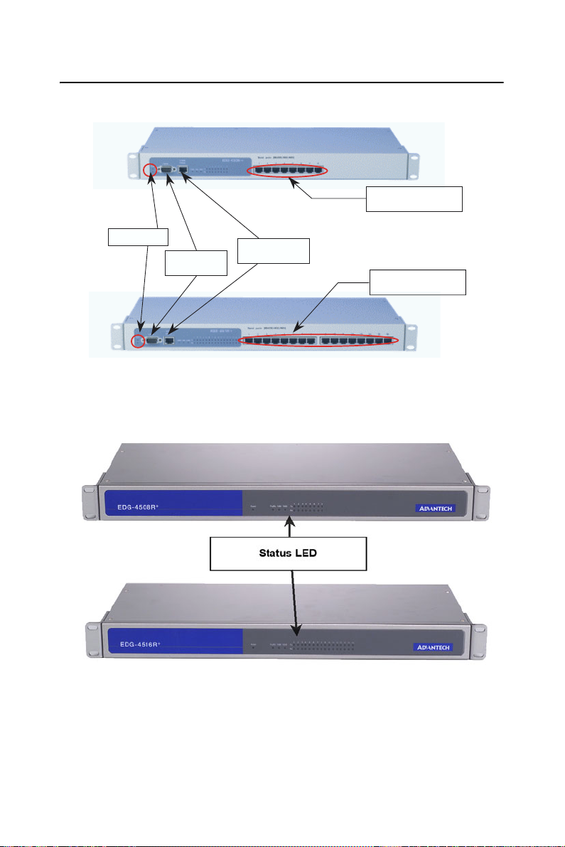
2.2 Connecting Hardware
Serial Ports
8 Ports for 4508+
Status LED
Console
Connector
Ethernet
Connector
Figure 2.2: EDG-4508+/4516+ Front Panel
Serial Ports
16 Ports for 4516+
Figure 2.3: EDG-4508R+/4516R+ Front Panel
EDG-4508+/4516+ User Manual 8
Page 17
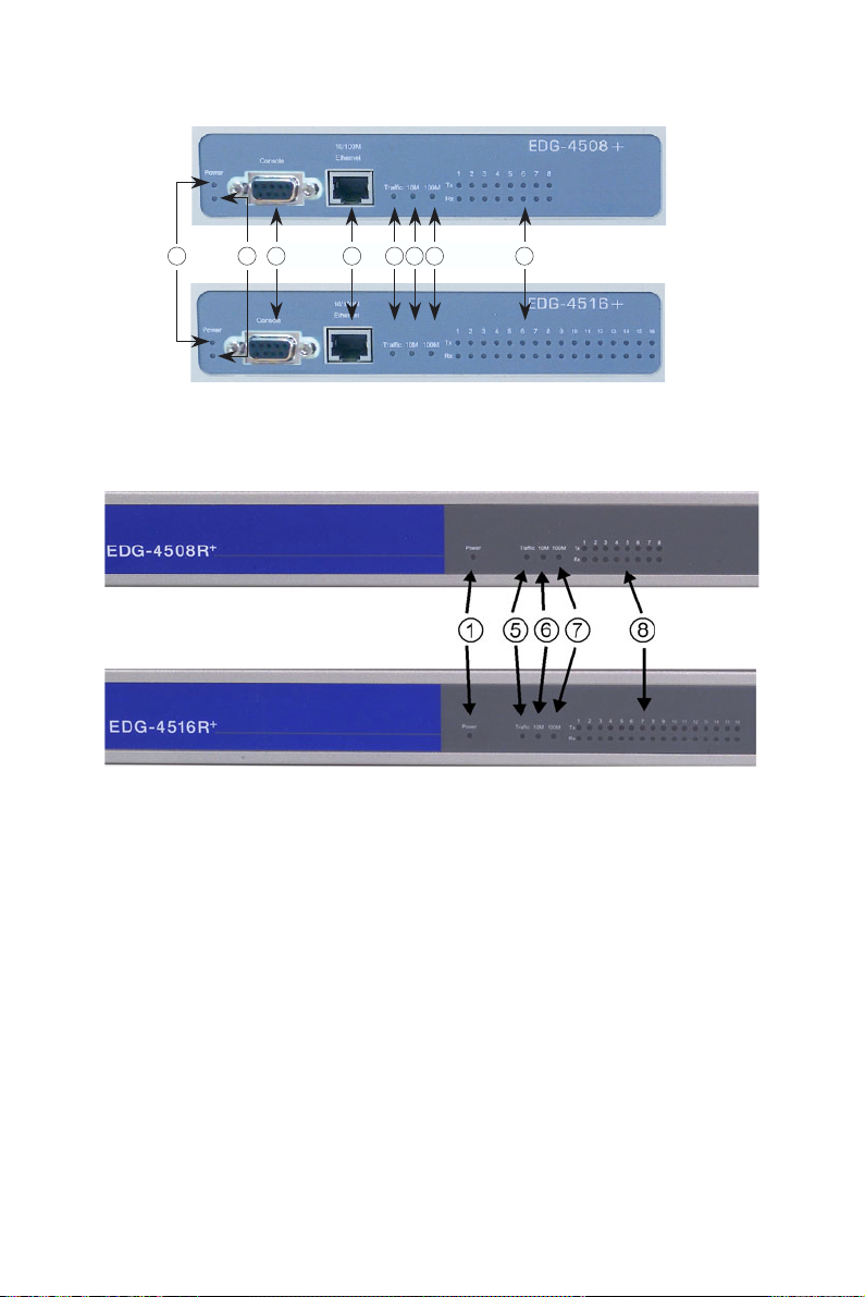
1 2 3 4 5 6 7 8
Figure 2.4: EDG-4508+/4516+ LED Indicators and Connectors
Figure 2.5: EDG-4508R+/4516R+ LED Indicators
9 Chapter 2
Page 18

Table 2.1: EDG-4508+/4516+ LED & Connector Definitions
Item LED Status Description
ON Power on
OFF Power off or no power
Status
!
Status
"
Console
#
Ethernet RJ-45 Ethernet Connector
$
Traffic
%
(Ethernet)
10M
&
100M
'
Tx (Port N)
N = 1~ 8/16
(
Rx (Port N)
N = 1~8/16
Flash
Steady
Dual Power Indicator
(Optional)
F Type Console connector
for Console Configuration
Use
ON
OFF
ON 10 Mbps speed
OFF
ON 100 Mbps speed
OFF
ON
OFF No data being transmitted
ON
OFF No data being received
Status Heart Beat
Monitoring
Device Locate Function
Enable
Ethernet data being
received/transmitted
No data being received/
transmitted
Invalid 10 Mbps network
link
Invalid 100 Mbps network
link
Serial port data being
transmitted
Serial port data being
received
EDG-4508+/4516+ User Manual 10
Page 19
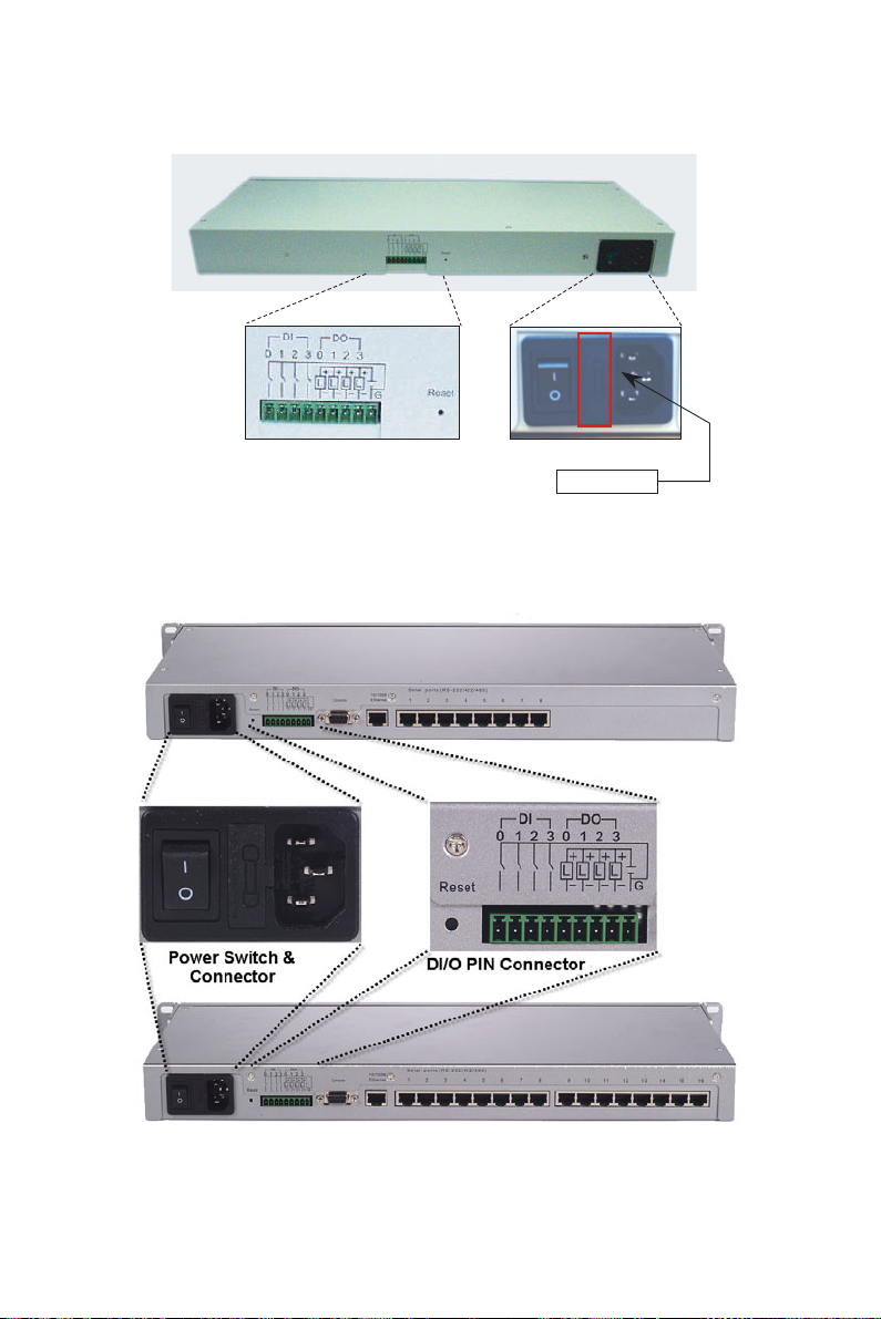
Power Switch & ConnectorDI/O PIN Connector
Fuse Storage
Figure 2.6: EDG-4508+/4516+ Rear Panel
Figure 2.7: EDG-4508R+/4516R+ Rear Panel
11 Chapter 2
Page 20
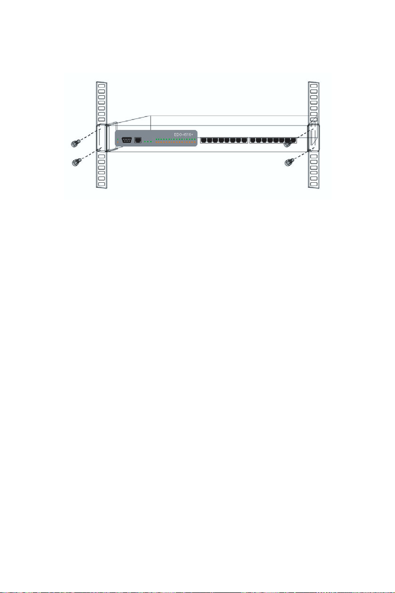
2.2.1 Rack Mounting
Figure 2.8: Rack Mounting
EDG-4508+/4516+ User Manual 12
Page 21
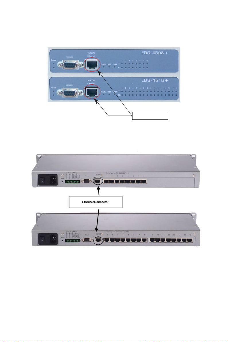
2.2.2 Network Connection
Ethernet Connector
Figure 2.9: Ethernet Connector of EDG-4508+/4516+
Figure 2.10: Ethernet Connector of EDG-4508R+/4516R+
13 Chapter 2
Page 22
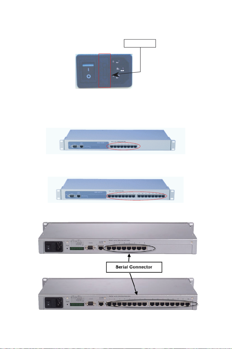
2.2.3 Power Supply Connection
Fuse Storage
Figure 2.11: Power Switch and Connector with Fuse
2.2.4 Serial Port Connection
Figure 2.12: 8 Ports RS-232/485/422 Serial Connector for EDG-4508+
Figure 2.13: 16 Ports RS-232/485/422 Serial Connector for EDG-4516+
Figure 2.14: RS-232/485/422 Serial Connectors for EDG-4508R+/4516R+
EDG-4508+/4516+ User Manual 14
Page 23

2.2.5 Ordering Information
• EDG-4504
4-port Ethernet to RS-232/422/485 Data Gateway
• EDG-4508+
8-port Ethernet to RS-232/422/485 Data Gateway for front wiring
access
• EDG-4508R+
8 port Ethernet to RS-232/422/485 Data Gateway for rear wiring access
• EDG-4516+
16-port Ethernet to RS-232/422/485 Data Gateway for front wiring
access
• EDG-4516R+
15-port Ethernet to RS-232/422/485 Data Gateway for rear wiring
access
• Communication Cable RJ48 to DB9 30cm (1701090300)
30 cm RJ48 to DB9 M-Type RS-232/422/485 Cable
• Communication Cable RJ48 to DB9 100cm (1703091001)
100 cm RJ48 to DB9 M-Type RS-232/422/485 Cable
• Terminal Connector (1654909900)
Terminal Connector for Test Usage
15 Chapter 2
Page 24
2.3 Installation
2.3.1 Install/Uninstall Driver & Utility
In order to use a PC and an Ethernet network to control serial devices
connected to EDG-4508+/4516+, you must first have a host running Windows 98/NT/2000/XP. This type of application also requires the host to
have an Ethernet card and the TCP/IP protocol installed. The following
are the required steps for installing EDG-4508+/4516+.
1. Insert the Advantech industrial communication CD-ROM into the
drive (e.g. D:\) on the host PC. Change the host computer's default
drive from C: to D:
2. Use your Windows Explorer or the Windows Run command to execute
the Setup program (the path for the Setup program on the CD-ROM
should be D:\ EDG-4508(R)+_4516(R)+\COMPortUtility\SETUP.EXE, if your default CD-ROM drive is D: ).
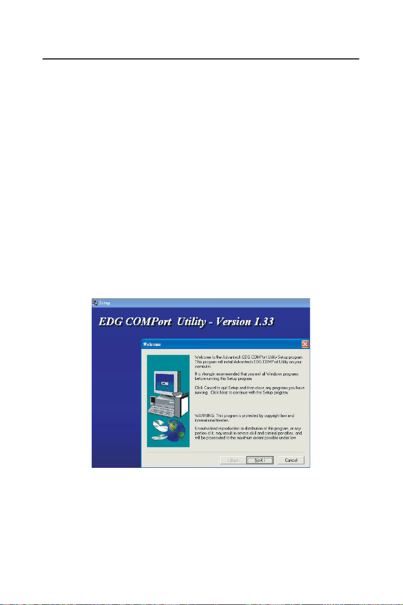
3. Upon executing the setup program, the Welcome Dialog Box will
pop-up. Press the "Next" button to continue.
EDG-4508+/4516+ User Manual 16
Page 25
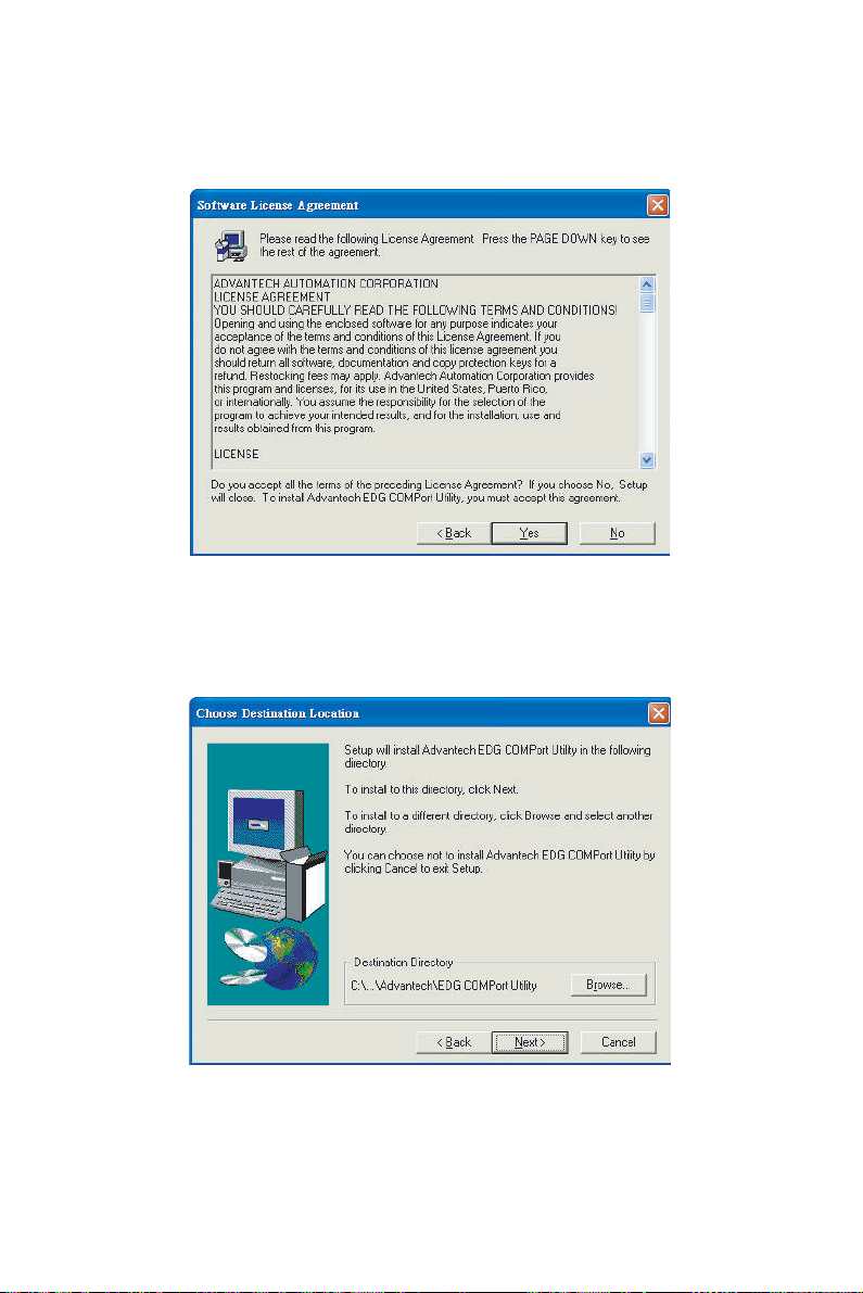
4. Carefully read the Software License Agreement, and press "Next" to
continue.
5. The Setup program will specify a default installation path, C:\Program
Files\Advantech\EDG COMPort Utility.
17 Chapter 2
Page 26
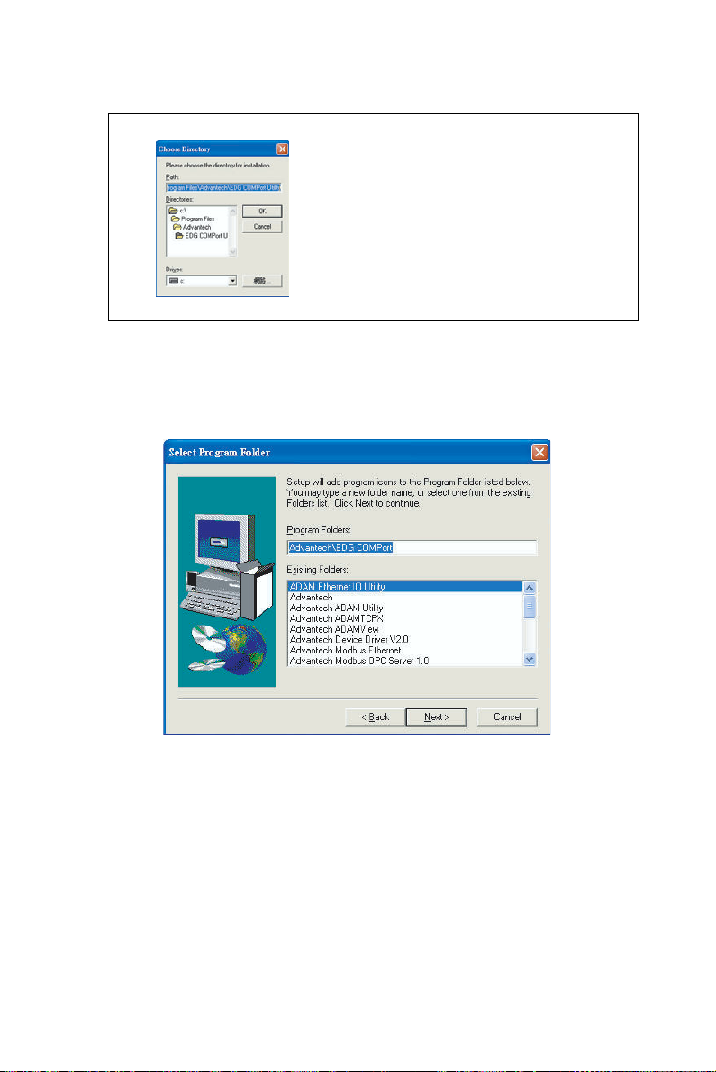
If a new destination path is necessary,
just click the Browse button to change
the path. After you have specified the
installation path, click the Next button.
6. In this step, you may select a specific program folder or just use the
default setting and press "Next".
EDG-4508+/4516+ User Manual 18
Page 27
7. After setup has copied all program files to your computer, click the
Finish button to finish the installation.
19 Chapter 2
Page 28

EDG-4508+/4516+ User Manual 20
Page 29

2
3
CHAPTER
Configuration
Page 30
Chapter 3 Configuration
3.1 Auto Search
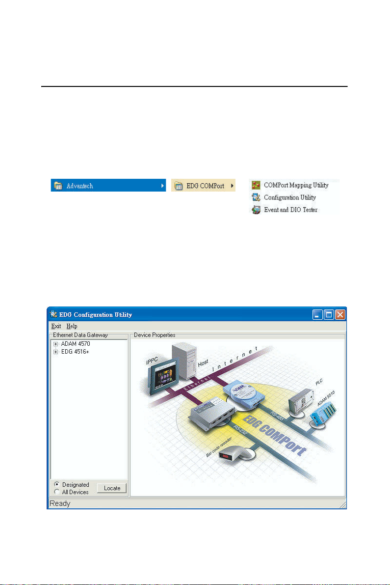
EDG-4508+ and EDG-4516+ provides an easy-to-use configuration utility to configure your Ethernet Data Gateway Device through an Ethernet
connection. The utility provides an auto-search function to show your
device(s) by simply executing the configuration utility program from the
Start Menu as follows.
Start Menu --> All Program --> Advantech --> EDG COMPort
This EDG configuration utility will automatically search all the EDG
devices on the network and show them on the left side of the utility. From
here you can easily configure various parameters for TCP/IP configuration. (In this example, the system finds the Ethernet Data Gateway device
for ADAM-4570 & EDG-4516+ in a local network)
EDG-4508+/4516+ User Manual 18
Page 31

You can click on the device name to show the features of the specific
device. Click on the "+" before the model name (e.g. EDG-4516+), and
the utility will expand the tree structure to show the individual device
name.
For Example, EDG Configuration Utility shows
"ADAM000102030415" after expanding the tree structure.
Default Device Name
Out Look for
Selected Device
Note When you run the EDG configuration utility for the
first time, the default device name is "MAC ID". In this
case, the device name "ADAM-000102030415"
means the device "MAC ID" is "00 01 02 03 04 15".
You can change the default device name in System
Tag of Device Properties.
Change Device Name Here
19 Chapter 3
Page 32

3.2 Locating EDG-4508+/4516+
The configuration utility provides a "Locate" function to assist you in
finding a specific device. You can select the EDG Series as a group or just
select one specific module, e.g. EDG-4508+ or EDG-4516+.
There are two different options for the Locate function
(1) Designated: locates a specific device for you.
1. Select "Designated" and click "Locate"
2. The "Status" LED will remain steady for 8 minutes.
3. If you choose another device and click on "Locate", the
"Status" LED of the previous choice will return to the heart beat
monitoring mode.
(2) All Devices: To locate all devices for the system.
1. Select "All Devices" and click "Locate"
2. All "Status" LED devices will remain steady for 8 minutes.
3. 8 minutes later or when someone enables the "Designated" Locate
function, the "Status" LED will return to its default heart beat
monitoring.
Locate Function Button
Device Locate Function Indicator
(1) Flash for Heart Beat Monitoring
(2) Steady for Device being Located
EDG-4508+/4516+ User Manual 20
Page 33

3.3 Device System Configuration
Four functional categories
Device Name
Device List
Device Description
Firmware
Version
The configuration utility only searches for EDG-4508+ and EDG-4516+
on the local network, and cannot search beyond a router or gateway.
Make sure that the EDG-4508+ or EDG-4516+ you want to monitor
resides in the same local network segment as the host PC.
Ethernet Data Gateway
In this column, you will find a list of EDG products if you use the configuration utility to auto-search.
Device Name
The configuration utility provides a default name to distinguish the different EDG devices from each other. You can update the default device
name based on your application. Please note that names are restricted to
128 characters, and it is usually best to choose a name you can remember.
Device Description
This field records the function, application and other information for each
EDG device in more detail for easy management and maintenance. You
can describe in your own words.
Firmware Version
In this field, the configuration utility presents the firmware version of the
EDG Series (e.g. V 1.10). You might need to refer to the firmware version to determine what functions are available on the EDG device. For
problems related to firmware version, please provide the firmware version number to our Customer Service.
21 Chapter 3
Page 34

3.4 Network Configuration
Ethernet Option
TCP/IP Option
Ethernet Option
MAC Address
This does not need configuration.
Link Speed
This function will show the current linking speed to be either 10Mbps or
100Mbps. However, the utility will auto-detect the current transmission
speed on the network segment and set the transmission speed for the
device accordingly.
Duplex Mode
The utility will detect the current transmission mode (half-duplex or
full-duplex) on the network segment, and set the transmission mode for
the device accordingly.
TCP/IP Option
IP address, Subnet Mask, Default Gateway
The IP address identifies your EDG device on the global network. Each
EDG device has the same default IP address 10.0.0.1. Obtain a specific
IP address from your network administrator and then configure each
EDG device with an individual IP address, related Subnet Mask and
Gateway Setting.
Note
EDG devices do not support auto IP address
configured by DHCP server.
EDG-4508+/4516+ User Manual 22
Page 35

3.5 Port Configuration
Port Setting Option
Port Configuration Option
Port Setting
You can modify the description for individual port settings in the Port
Setting Option.
Name
Show Port Name
8 Ports for EDG-4508+
16 Ports for EDG-4516+
Description
Show individual description for each port.
You can change the description for your connected module to identify the
connection from EDG Configuration Utility.
23 Chapter 3
Page 36

Port Configuration
You can modify port configuration in this Configuration Option such as
Type, Parity, Flow Control, Data Bits, Stop Bits, Baud Rate and Host Idle
Timeout.
Type
Serial Port Type
You can change the connection type for your module to: RS-232, RS-422
or RS-485.
EDG-4508+/4516+ User Manual 24
Page 37

Parity
Parity Check Type
You can follow the parity check type of your connected module. The following types are provided.
• None
• Odd
• Even
• Mark
• Space
Flow Control
Flow Control Type
You can choose the flow control type of your connected module. The following types are available.
• None
• Xon/Xoff
• RTS/CTS
• DTR/DSR
25 Chapter 3
Page 38

Data Bits
Data Bits Type
You can choose the number of Data Bits of your connected module to be
5, 6, 7 or 8.
Stop Bits
Stop Bits Type
You can choose 1, 1.5 or 2 Stop Bits for your connected module
EDG-4508+/4516+ User Manual 26
Page 39

Baud Rate
Flow Control Type
You can choose the Baud Rate of your connected module. The following
rates are available:
• 7,200
• 9,600
• 14,400
• 19,200
• 38,400
• 57,600
• 115,200
• 230,400
* Set All Port
The ‘Set All Port’ function helps you set all serial ports at one time. All
you need is to set one port and click the "Set All Port" button. The other
ports will then follow the first port that you have set up. This is faster than
setting up 8 ports (4508+) or 16 ports (4516+) with the same settings.
27 Chapter 3
Page 40

Host Idle Timeout
n
The ‘Host Idle Timeout’ setting monitors the connection between the host
and the device. If the ‘Host Idle Timeout’ setting time is reached, the
device will release the resources allocated to the port mapping. This pre-
vents a stalled host from affecting the connected device. .
Note
Host Idle Timeout and Auto Reconnection
Function Detail
Host Provide
Auto Reconnection Function
Ethernet
digital
EDG Device Support
Host Idle Timeout Detect Functio
Auto Reconnection
An auto reconnection function is provided by the host. Under certain circumstances (such as: Ethernet connection failure, device power down or
other device issues) the auto reconnection function will try to reconnect
the assigned device.
EDG-4508+/4516+ User Manual 28
Page 41

3.6 Security Configuration
For security reasons, you are highly recommended to use EDG’s security
features. The EDG configuration utility provides security functions for
the network structure.
Only configure the allowed IP
The system will auto detect the IP address for the currently connected
computer. If you enable this function, only your local computer can
access this EDG Device.
*If you use Dynamic IP Assignment by the DHCP Server, we suggest
that this function is not enabled.
Allow any IP to access
If you enable this function, any IP address can access your device and
there is no access restriction.
Specified IP can access EDG device
You can assign a specific IP address that have access to the EDG device.
Assign the IP address and click on "Add" to add a specified IP or choose
the IP address list below and click on "Delete" to remove the IP from the
access list.
29 Chapter 3
Page 42

EDG-4508+/4516+ User Manual 30
Page 43

2
4
CHAPTER
Port Mapping Utility
Page 44

Chapter 4 Port Mapping Utility
4.1 Overview
The purpose of the port mapping utility is to help you manage all ports on
one Windows 98/NT/2000/ME/XP platform. The utility displays three
types of ports: used ports, unused ports and EDG ports. Please follow the
Virtual COM port setting steps.
4.2 Virtual COM Port Settings
1. Click "+" at "Unused Ports" to expand the unused port lists, and select
the port that you want to configure.
Click "+" to expand the list
Unused Ports List
EDG-4508+/4516+ User Manual 32
Page 45

2. Click the ADD button to assign a COM port to an EDG device.
Module of Installed Device
You can choose between all connected EDG devices. In this example,
"EDG-4516+" was chosen.
IP Address of Installed Device
Enter the IP address you assigned in chapter 3.4.
Port of Installed Device
Choose the port where you want to setup: 8 ports for EDG-4508+ and 16
ports for EDG-4516+.
Properties (Auto Reconnect Function)
Sometimes, the system may crash because the EDG device is interrupted
or powered-off by accident. In such a situation, the host PC need to
reconnect to the EDG device automatically.
EDG devices provide an "Auto-reconnect" function for this purpose. If
the EDG device loses the connection to its host, the driver will automatically try to re-establish the connection. When the connection is working
again, the host PC's commands will be automatically received by the
EDG Series again. Reconfiguration is not necessary, so this function
enhances the reliability of the system.
33 Chapter 4
Page 46

Memo
(
+)
(COM22 is mapping to Port 2 of EDG-4516+)
You can add a description to the port setting if necessary.
Add
Click here to add a single port setting to your specification.
Add All
You can assign all ports to follow current settings by clicking the "Add
All" button. This is more convenient than adding ports individually. For
this example, we have selected COM21 and made all necessary settings
for Port 1 of EDG-4516+. After clicking on the "Add All" button, the
COM Port Mapping Utility will assign the COM21 ~ COM36 mapping to
Port 1 ~ Port 16.
COM21 is mapping to Port 1 of EDG-4516
EDG-4508+/4516+ User Manual 34
Page 47

Note
If you assigned a different COM port to the
same EDG series module port, the following
dialog box will remind you.
4.3 Inquiring Virtual COM Port Setting
You can check the virtual COM port setting by clicking on the EDG
device’s ports. In this case, COM11 is assigned to Port 1 of EDG-4516+.
35 Chapter 4
Page 48

4.3.1 Updating EDG Firmware
Updating Firmware
Advantech continually upgrades its firmware. You can use the download
function located on the Port Mapping utility to carry out the upgrade procedure. Please access Advantech's web site at http://www.advantech.com
to download the required computer file and then follow these instructions.
1. Click on the Update FW icon in the toolbar.
2. Locate and then select the filename of the firmware that you have
downloaded.
3. After the firmware has been downloaded into the EDG device, click
the Reboot button.
4. Restart the host PC so that it can recognize the updated firmware on the
EDG device.
Note
After clicking the Reboot button, the configuration utility will not reboot the EDG device.
EDG-4508+/4516+ User Manual 36
Page 49

4.3.2 Self Test Function
Test
The purpose of this test is to confirm that the communication from the
host PC to the EDG device is OK. When the test is selected, an external
test will be performed to check that the connection signal between each
port is working properly. For this test, you will need to connect each port
to a Loopback tester. Refer to the following chart for specifications of this
Loopback tester. The Loopback test only applies to RS-232 mode. It is
divided in two parts: Signal test and Communication Parameters test.
1. Click on the Test button in the Port Mapping utility. A message
will confirm that the loopback connector have already been connected with the EDG COM port. If ready, click the Start button to
start the test.
Test Fail (Without Loopback Connector)
Test ok
37 Chapter 4
Page 50

Signal Test
• RTS->CTS: Checks the RTS and CTS signals between two ports.
• DTR->RI: Checks the DTR and RI signals between two ports.
• DTR->DSR: Checks the DTR and DSR signals between two ports.
• DTR->DCD: Checks the DTR and DCD signals between two ports.
Communication Parameters Test
• Baud rate: From 50 bps to 230 kbps
• Data bits: 5, 6, 7, 8
• Stop bits: 1, 1.5, 2
• Parity: odd, even, none, space, mark
2. Click the OK button to return to the port mapping window. All the
ports in the EDG Series are tested ok.
EDG-4508+/4516+ User Manual 38
Page 51

Delete
You can delete Port Mapping Setting by clicking the button.
Apply
If any changes are made, please press the button to confirm your
modifications.
Exit
If you want to quit the utility, please click on the button. If any
changes are made in the COM Port Mapping setting, the system reboot
requirement will show up. Please reboot your system to make sure your
changes will work.
39 Chapter 4
Page 52

4.3.3 Save the Configuration
If you want to save or recover the configuration, you can select the
"Import/Export" items.
1. a. Select "File"
b. Select "Import" or "Export".
2. Save or open the configurations
EDG-4508+/4516+ User Manual 40
Page 53

2
5
CHAPTER
Web-Based
Configuration
Page 54

Chapter 5 Web-Based Configuration
5.1 Overview
EDG devices can be configured through a web interface. By using a standard web browser, the same procedure as with the Windows configuration utility can be used. In the browser’s address field, enter the IP
Address of your EDG device. The default IP setting is 10.0.0.1, but you
should use the IP which you have previously assigned for this device.
Once the IP is entered, you will be presented with the following windows.
5.2 Access Web Page
Step 1. Enter ID and Password
The default ID and password is root, key this into both fields..
Step 2. Web Based Configuration Welcome
After authorization, the main configuration menu will be displayed.
EDG-4508+/4516+ User Manual 42
Page 55

5.3 Network Configuration
Under network configuration, there are: MAC address, IP Address, Subnet Mask and Default Gateway. Enter the corresponding values for your
network environment.
Step 1. Enter IP Address, Subnet Mask and Default Gateway
Step 2. Press ‘Save’ to store the settings.
Note
All new configurations will take effect after
reset. The reset function is located on the main
menu of the Web Configuration.
43 Chapter 5
Page 56

5.4 Port Configuration
Under port configuration, you can as sign the type and host idle timeout
for individual ports.
Note
EDG-4508+ and EDG-4516+ provide RS-232 /
RS-4852 / RS-422.
Note
The Host Time Out function is similar to the
one in the Configuration Utility.
EDG-4508+/4516+ User Manual 44
Page 57

5.5 DI/O Event Configuration
In event configuration, you can assign an DI event by enabling the check
box and choosing the optimized action mode, Server IP and TCP Port for
the active event.
DI 0, DI 1, DI 2, DI 3 Options for Event 1 will be activated when any one of DI
signal meets the Action option. The event will be monitored on the Server and port
of your assignment.
Action Description
L2H: Low to High
H2L: High to Low
CHG: Change
45 Chapter 5
Page 58

5.6 Reset Configuration
All configurations will take effect after this reset step. Press the reset button and the system will give a reset response. It will take a few
seconds to reconnect with the new values.
EDG-4508+/4516+ User Manual 46
Page 59

2
6
CHAPTER
Console Configuration
Page 60

Chapter 6 Console Configuration
6.1 Overview
The purpose of the Console Configuration is to help you manage your
device in console mode. One of the main functions of the console mode is
to change the web configuration login password. You can use terminal
software like Hyper Terminal, Telix and other related terminal software.
6.2 Hyper Terminal Connection
Step 1. Connecting the cable
You can connect to the EDG device’s console port with a RS-232 DB9
M-type communication cable, with the other end connecting to the host’s
serial port. Make sure the connection is OK and then run the Hyper Terminal Program on your host.
Console Port
Step 2. Creating a new connection
You can create a new connection and assign a connection name for the
console configuration.
EDG-4508+/4516+ User Manual 48
Page 61

Step 3. Selecting a COM Port
Confirm that the console configuration works ok.
Step 4. COM Port Setting
To connect the EDG series for console configuration, the port setting
should match the EDG series' default setting.
Console Configuration Default Setting
Baud Rate: 57600
Data Bits: 8
Parity: None
Stop bits: 1
Flow control: Hardware.
49 Chapter 6
Page 62

Step 5. Connecting Successfully
After connecting the device in console mode, you can simply type the
"Help" command to show the Supported Command Lists
6.3 Command List
Command Function
version Displays the current firmware version
log Displays the log file
date Displays or sets the date
time Displays or sets the time
net Displays the net configuration
port Displays the status of port(s)
event Displays the configuration of event(s)
ping Sends ICMP ECHO_REQUEST packets to network hosts
exit Terminates shell session
web Sets web password or saves web configuration
reboot Reboots the system
• version
[Usage] version
[Function] displays the current firmware version
>version
Current version of firmware is 1.11-1.11
EDG-4508+/4516+ User Manual 50
Page 63

• log
[Usage] log
[Function] displays log file
>log
[05-09-2003 17:01:17] System up
• date: displays or sets the date
[Usage] date
[Function] displays the date
>date
Current date is 05-09-2003
[Usage] date [mm-dd-yy [dse]]
[Function] sets the date
>date 06-09-03
>date
> Current date is 06-09-2003
• time: displays or sets the time
[Usage] time
[Function] displays the configuration
>time
Current time is 17:17:30
[Usage] time [hh.mm.ss]
[Function] sets the time
>time 17:17:50
>time
Current time is 17:17:55
51 Chapter 6
Page 64

• net
[Usage] net
[Function] displays the configuration of net
>net
Current net is ip 172.18.3.226 gw 0.0.0.0 netmask 255.255.255.0
[Usage] net set ip d.d.d.d gw d.d.d.d netmask d.d.d.d
[Function] sets the configuration of net
>net set ip 172.18.3.227 gw 0.0.0.0 netmask 255.255.255.0
>net
Current net is ip 172.18.3.227 gw 0.0.0.0 netmask 255.255.255.0
[USAGE] net save
[FUNCTION] saves the configuration of net to system
Note
You should use the net save command to
activate the changes.
EDG-4508+/4516+ User Manual 52
Page 65

• port
[USAGE] port [nn | all]
[FUNCTION] displays the status of port(s)
>port all
The Port01 is type 422, idleto 30, idle
The Port02 is type 232, idleto 30, idle
The Port03 is type 232, idleto 30, idle
The Port04 is type 232, idleto 30, idle
The Port05 is type 232, idleto 30, idle
The Port06 is type 232, idleto 30, idle
The Port07 is type 232, idleto 30, idle
The Port08 is type 232, idleto 30, idle
The Port09 is type 232, idleto 30, idle
The Port10 is type 232, idleto 30, idle
The Port11 is type 232, idleto 30, idle
The Port12 is type 232, idleto 30, idle
The Port13 is type 232, idleto 30, idle
The Port14 is type 422, idleto 30, idle
The Port15 is type 422, idleto 30, idle
The Port16 is type 422, idleto 30, idle
[USAGE] port [nn | all] type [232|422|485]
[FUNCTION] sets the type of port(s)
>port 3 type 485
>port 3
The Port03 is type 485, idleto 30, idle
[USAGE] port [nn | all] idleto [0 - 4095]
[FUNCTION] sets the idle timeout of port(s)
>port 3 idelto 45
>port 3
The Port03 is type 485, idleto 45, idle
[USAGE] port save
[FUNCTION] saves the configuration of port to system
Note You should use the net save command to
activate the changes.
53 Chapter 6
Page 66

• event
[USAGE] event [nn | all]
[FUNCTION] displays the configuration of event(s)
[USAGE] event nn iomap xx action [L2H|H2L|CHG] server d.d.d.d:d
[FUNCTION] sets the configuration of event
[USAGE] event [nn | all] clear
[FUNCTION] clears the configuration of event
>event 2 iomap f action L2H server 172.18.3.58:503
>event 2
The Event2 is iomap f action L2H server 172.18.3.58:503
>event 2 clear
>event all
The Event1 is iomap f action CHG server 172.18.3.58:502
The Event2 is disable
The Event3 is disable
The Event4 is disable
The inverse of DI value is off
[USAGE] event diinv [0|1]
[FUNCTION] sets the inverse of DI value on/off
>event diinv 1
>event all
The Event1 is iomap f action CHG server 172.18.3.58:502
The Event2 is disable
The Event3 is disable
The Event4 is disable
The inverse of DI value is on
>event diinv 0
>event all
The Event1 is iomap f action CHG server 172.18.3.58:502
The Event2 is disable
The Event3 is disable
The Event4 is disable
The inverse of DI value is off
[USAGE] event save
[FUNCTION] saves the configuration of event to system
Note
You should use the net save command to
activate the changes.
EDG-4508+/4516+ User Manual 54
Page 67

• ping
[USAGE] ping addr (addr: IP address of destination host)
[FUNCTION] Sends ICMP ECHO_REQUEST packets to network
hosts
>ping 172.18.3.226
32 bytes from 172.18.3.226: icmp_seq=0 ttl=64 time=1 ms
32 bytes from 172.18.3.226: icmp_seq=1 ttl=64 time=1 ms
32 bytes from 172.18.3.226: icmp_seq=2 ttl=64 time=1 ms
32 bytes from 172.18.3.226: icmp_seq=3 ttl=64 time=1 ms
• exit
[USAGE] exit
[FUNCTION] Terminates shell session
>exit
Bye!
• web
[USAGE] web password ****
[FUNCTION] sets the web password
>web password 1234
>web save
[USAGE] web save
[FUNCTION] saves the configuration of web to system
>web save
Note
You should use the web save command to
activate the changes.
• reboot
[USAGE] reboot
[FUNCTION] reboots the system
>reboot
EDG 4516+ Firmware Version 1.11 Build-118
[05-09-2003 18:25:57] System up
55 Chapter 6
Page 68

EDG-4508+/4516+ User Manual 56
Page 69

2
7
CHAPTER
Universal Serial Device
Gateway
Page 70

Chapter 7 Universal Serial Device
Gateway
Advantech EDG-4508+/4516+ provides a mechanism that allows user to
upgrade the firmware. After upgrading the firmware, EDG-4508+/4516+
will turn into universal serial device gateway and denominate "EDG4508+U/4516+U". EDG-4508+U/4516+U allows nearly any device to
serial ports to connect to the Ethernet and share networks quickly. It
provides a fast, simple and cost-effective way to bring the advantages of
remote management and data accessibility to thousands of devices that
cannot connect to the network.
EDG-4508+U/4516+U supports standard networking application
programming interface (API) such as WinSock and Socket, therefore,
your serial devices can be used in most popular operating systems with
EDG-4508+U/4516+U. Moreover, EDG-4508+U/4516+U allows the
serial device to communicate with other devices by peer-to-peer without
any intermediate host PCs and software programming, which saves cost
and effort.
7.1 EDG-4508+/4516+ Firmware updated procedure
This session introduces how to update the firmware from EDG-4508+/
4516+ to EDG-4508+U/4516+U. We will take EDG-4508+ as an
example to explain the following procedure.
1. Execute the application "EDG serial download and testing utility".
Select your model name and IP address, and then press "Download
FW" button.
2. Click the "Open button" in the Window of "EDG-4508+ Download
Firmware". Select the right firmware file (*.exf) to download to your
EDG. (All of the firmware files are located in C:\\Program
Files\Advantech\EDG COM Port Utility\firmware\ when you install
the EDG COM port utility.)
File Name Description
4508+Uv200.exf The firmware of EDG-4508+U; version 2.0.
4508+v200.exf The firmware of EDG-4508+; version 2.0.
4516+U200.exf The firmware of EDG-4516+U; version 2.0
4516+v200.exf The version of EDG-4516+; version 2.0
EDG-4508+/4516+ User Manual 58
Page 71

1
2
3
Figure 7.1:
3. Press "Start" button to start the firmware download procedure.
Figure 7.2:
59 Chapter 7
Page 72

4. When the firmware download procedure is done, you will discover the
model name of the EDG Configuration Utility is changed from
EDG-4508+ to EDG-4508+U. Besides, it will add a new function:
"Setting" in EDG Configuration Utility instead of "Security". The
"Setting" in EDG Configuration Utility allows user to configure the
setting of EDG-4508+U/4516+U.
Figure 7.3:
5. Configure the setting of your EDG-4508+U. Press the "Settings" tag in
the EDG Configuration Utility.
Figure 7.4:
EDG-4508+/4516+ User Manual 60
Page 73

TCP Port number
Figure 7.5:
The TCP port number represents the source port number in TCP connections, and is the number used to identify the channel for remote initiating
connections. Range: 1-65535.
If an unknown caller wants to connect to the system and asks for some
services, they need to define the TCP port to carry a long-term conversation.
Each node on a TCP/IP network has an IP address, and each IP address
can allow connections on one or more TCP port. The well-known TCP
port are those that have been defined; for example, port 23 is used for Telnet connections. There are also custom sockets that users and developers
define for their specific needs. The default TCP port of EDG-4508+U/
4516+U is 5200. Opening a TCP session to port 5200 will form a raw
TCP/IP connection to the serial port.
Note
1: If the serial port is in use, the socket
connection will be refused.
2: Timing between serial signals (such as DSR,
RTS, and DCD) is not preserved, and the state
of such signals is not readable.
Only configure the authorized IP
Figure 7.6:
This option is enabled in order to protect all configuration settings from
being changed inadvertently.
61 Chapter 7
Page 74

Allow any IP to access
Figure 7.7:
If this option is enabled, any PC can access data from this EDG-4508+U/
4516+U.
Specified IP which can access
If you do not want many PCs to have the access right, you can limit at
most 32 PCs to access data from this EDG-4508+U/4516+U.
Port Mode
Figure 7.8:
The EDG-4508+U/EDG-4516+U supports "Data mode" communication.
In this mode, serial devices that connect to the EDG-4508+U/
EDG-4516+U can transmit data to another networking device. You only
need to key-in the item "Peer for Receiving Data". The item "Setting for
Hang-up Sequence" will become gray.
EDG-4508+/4516+ User Manual 62
Page 75

1. Select port 1 ~ port 8 if you are using EDG-4508+U. Select port 1 ~
port 16 if you are using EDG-4516+U.
2. Key-in the data idle time. The default is 60 seconds. If you want to
keep connection continually, you can key-in "0". Data idle Time is the
time period in which the device waits for data. If the EDG-4508+U/
4516+U does not receive data over an established idle time, the
EDG-4508+U/4516+U will disconnect temporarily. When the data
comes to the EDG-4508+U/4516+U, it will reconnect automatically.
Users do not need to reconnect.
3. Key-in another IP address of networking device which you want to
connect.
4. Key-in another TCP port of networking device which you want to
connect. If you want to connect to the port of another EDG-4508+U/
4516+U, you have to note the following information.
TCP port of EDG-4508+U/4516+U: &&&&
TCP port of EDG-4508+U/4516+U's port1: &&&& +1
TCP port of EDG-4508+U4516+U's port2: &&&& +2
For example:
TCP port of EDG-4508+U/4516+U that you want to connect: 5220.
TCP port of Port 1: 5220 +1=5221
TCP port of Port 2: 5220 +2=5222
5. If you want to connect to a PC or any system, you have to key-in the
TCP port of that PC or system.
How do you restore the firmware to EDG-4508+/4516+?
If you want to restore the firmware to EDG-4508+/4516+, please follow
below procedure. The EDG-4508+ is taken as an example to explain the
following procedure.
1. Execute the application "EDG serial download and testing utility".
Select your model name and IP address, and then press "Download
FW" button.
2. Click the "Open button" in the Window of "EDG-4508+ Download
Firmware". Select the right firmware file (*.exf) to download to your
EDG. (All of the firmware files are located in C:\\Program
Files\Advantech\EDG COM Port Utility\firmware\ when you install
the EDG COM port utility.)
63 Chapter 7
Page 76

File Name Description
4508+Uv200.exf The firmware of EDG-4508+U; version 2.0.
4508+v200.exf The firmware of EDG-4508+; version 2.0.
4516+U200.exf The firmware of EDG-4516+U; version 2.0
4516+v200.exf The version of EDG-4516+; version 2.0
1
2
Figure 7.9:
EDG-4508+/4516+ User Manual 64
3
Page 77

3. Press "Start" button to start the firmware download procedure.
Figure 7.10:
4. When the firmware download procedure is done, you will discover the
model name of the EDG Configuration Utility is changed from
EDG-4508+U to EDG-4508+. Besides, the function "Security" of
EDG Configuration Utility will be restored.
Figure 7.11:
65 Chapter 7
Page 78

7.2 Network Architecture and Example Code
The EDG-4508+U/4516+U is an advanced peer-to-peer data gateway
unit. It extends traditional RS-232/422/485 interfaces to Ethernet network. Through networking, you can control and monitor remote serial
devices either over a LAN or over the WAN. Since the EDG-4508+U/
4516+U is connected through a TCP/IP network, you will need to know
some basic facts about networking in order to get the server hooked up
correctly.
The EDG-4508+U/4516+U provides three types of network architecture:
polling, event handling and peer-to-peer. You can use the EDG-4508+U/
4516+U in any operation system with standard networking API such as
WinSock and Socket. If you want to develop application programs to
access the EDG-4508+U/4516+U, the following illustrates several example codes for your reference. The three network types are: polling, event
handling and peer-to-peer.
EDG-4508+/4516+ User Manual 66
Page 79

7.2.1 Polling Network Architecture
If you want to use host PC to poll the serial devices, which connect to
EDG-4508+U/4516+U via Ethernet, you can use polling network
architecture.
Figure 7.12: Network Architecture-Polling
Host PC cre ate TCP s ock et
Connect to
EDG-4508+U/ EDG-4516+U
Send data to
EDG-4508+U/ EDG-4516+U
Receive data from
EDG-4508+U/ EDG-4516+U
Disconnection
Figure 7.13: Flow chart-Polling Network
67 Chapter 7
Page 80

Example (EDG-4508+U):
SOCKADDR_IN Dst4508UAddr;
SOCKET Dst4508USock;
char RxData[10];
memset(&Dst4508UAddr, 0, sizeof(SOCKADDR_IN));
Dst4508UAddr..sin_family = AF_INET;
Dst4508UAddr..sin_addr.s_addr = inet_addr("10.0.0.1");
//Indicate the IP Address of EDG-4508+U that you want to connect.//
Dst4508UAddr..sin_port = htons(5201);
// Indicate which port of EDG-4508+U you want to access//
// TCP port no. of Port1 = TCP port +1//
// TCP port no. of Port2 = TCP port +2//
Dst4508USock = socket(AF_INET, SOCK_STREAM, 0));
// EDG-4508+U creates the TCP socket//
connect(Dst4508USock, (sockaddr *)&Dst4508UAddr,
sizeof(Dst4508UAddr));
//Connect to the EDG-4508+U//
send(Dst4508USock, "0123456789", 10, 0);
//Send data "0123456789" to the port of EDG-4508+U//
recv(Dst4508USock, RxData, 10, 0);
//Receive the data from the port of EDG-4508+U//
closesocket(Dst4508USock);
//Disconnect from the EDG-4508+U//
EDG-4508+/4516+ User Manual 68
Page 81

7.2.2 Event-handling Network Architecture
If an event occurs from serial devices connected to the EDG-4508+U/
4516+U, the host PC can get the data via the Ethernet. You can use the
event-handling network architecture.
Figure 7.14: Network architecture: Event-handling
Define the TCP port of Host PC
Ho st PC cr ea tes t h e sock e t
Accept the connection from
EDG-4508+U/ EDG-4516+U
Receive data from
EDG-4508+U/ EDG-4516+U
Disconnection
Figure 7.15: Flow chart: Event-handling network
69 Chapter 7
Page 82

Example (EDG-4508+U):
SOCKADDR_IN HostAddr;
SOCKET HostSock;
SOCKADDR_IN ClntAddr;
SOCKET ClntSock;
int ClntAddrLen;
char RxData[256];
memset(&HostAddr, 0, sizeof(SOCKADDR_IN));
HostAddr..sin_family = AF_INET;
HostAddr..sin_addr.s_addr = INADDR_ANY;
HostAddr.sin_port = htons(5201);
//Define the TCP port of host PC. It's the same as the value that you keyin it in the "Peer for Receiving Data" item of configuration utility//
HostSock = socket(AF_INET, SOCK_STREAM, 0);
// Create the socket of TCP on the Host//
bind(HostSock,(sockaddr *)&HostAddr, sizeof(HostAddr));
listen(HostSock, 1);
ClntAddrLen=sizeof(ClntAddr);
ClntSock = accept(HostSock, (sockaddr *)&ClntAddr, &ClntAddrLen);
//The host PC accepts the connection request from the EDG-4508+U/
EDG-4516+U //
recv(ClntSock, RxData, 256, 0);
//Receive the data from the port of EDG-4508+U/EDG-4516+U //
closesocket(ClntSock);
//Disconnect from the EDG-4508+U/EDG-4516+U //
EDG-4508+/4516+ User Manual 70
Page 83

7.2.3 Peer-to-Peer Network Architecture
If you want to transmit data from one serial device to another serial
device via the Ethernet, you can add EDG-4508+U/4516+Us at both
sides and use peer-to-peer network architecture.
Figure 7.16: Network architecture: Peer-to-peer
Complete the setting of #1
EDG-4508+U/ EDG-4516+U
Key-in the information of #1
EDG-45 08+U/ E DG-4516 +U in c onfigur ation utilit y
Complete the setting of #2
EDG-4508+U/ EDG-4516+U
Key-in the information of #2
EDG-45 08+U/ E DG-4516 +U in c onfigur ation utilit y
Check the communication parameters of two
EDG- 4508 +U/ E DG-4516 +Us to b e the same
Two
EDG- 4508+ U/ E DG-4516 +Us s end/recei ve data
each other
Figure 7.17: Flow chart: Peer-to-Peer network
71 Chapter 7
Page 84

Example (EDG-4508+U):
1. Complete the setting of #1 EDG-4508+U
#1 EDG-4508+U
Module name: Office
IP address: 172.20.20.111
TCP port: 5200
172.20.20. 222
5222
Figure 7.18: #1 EDG-4508+U Configuration Utility
EDG-4508+/4516+ User Manual 72
Page 85

2. Find out the IP address and TCP port of #2 EDG-4508+U that you
want to connect.
#2 EDG-4508+U
Module name: Factory
IP address: 172.20.20.222
TCP port: 5220
5220
172.20.20.111
5201
Figure 7.19: #2 EDG-4508+U Configuration Utility
73 Chapter 7
Page 86

3. Key-in the IP address and TCP port of #2 EDG-4508+U in #1
1
EDG-4508+U configuration utility.
172.20.20.222
5222
IP address of #2 EDG-4508+U
TCP port of #2 EDG-4508+U port 2
Figure 7.20: Key-in information of #2 EDG-4508+U
4. Follow the above procedure and complete the setting of #2
EDG-4508+U in the configuration utility.
5220
172.20.20.111
5201
IP address of #1 EDG-4508+U
TCP port of #1 EDG-4508+U port
Figure 7.21: Key-in information of #1 EDG-4508+U
EDG-4508+/4516+ User Manual 74
Page 87

5. Check the communication parameters of both EDG-4508+Us are the
same. If not, it might not work. Please check the "Baud rate", "Flow
control", "Parity", "Data bit" and "Stop bit".
EDG 4508+U
ADAM-000102030
EDG 4508+U #1
Figure 7.22: Communication parameters of #1 EDG-4508+U
EDG 4508+U
ADAM-000102030
EDG 4508+U #2
Figure 7.23: Communication parameters of #2 EDG-4508+U
6. #1 EDG-4508+U and #2 EDG-4508+U send/receive data each other.
75 Chapter 7
Page 88

7.3 Web-Based Configuration for EDG-4508+U/4516+U
EDG-4508+U/4516+U also support web-based configuration function.
All operations are the same as EDG-4508+/4516+. You can configure
EDG-4508+U/4516+U by internet browser.
Further information about the Web-based Configuration, please refer to
chapter 5.
7.3.1 Access web page
Step1: Enter ID and Password.
The default ID and password is the root/root; key-in in the correct fields.
Step2: The Main Menu of Web-Based Configuration
After authorization, the configuration main menu will show up.
EDG-4508+/4516+ User Manual 76
Page 89

7.3.2 Network Configuration
Under network configuration, there are MAC address, IP Address, Subnet
Mask and Default Gateway and Listen TCP Port Number. Enter the
corresponding values for your network environment.
Step1. Enter MAC address, IP Address, Subnet Mask and Default
Gateway and Listen TCP Port Number.
Step2: If you do any modification in EDG-4508+U/4516+U network
configuration, please press "save" button to save the
configuration.
Note
All new configurations will take effect after
reset. Reset function is located on the main
menu of the web configuration.
77 Chapter 7
Page 90

7.3.3 Port Configuration
Under port configuration, you can assign the type, host idle timeout and
configure the connected IP and TCP port for each port.
For instance, if the port 1 of EDG-4516+U#1 connects with the port 8 of
EDG-4516+U#2, please fulfill Port 8 IP address and TCP port of
EDG-4516+U #2 in port 1 information of EDG-4516+U #1 port
configuration.
Note
The host time out function is similar to the one
in the Configuration Utility.
EDG-4508+/4516+ User Manual 78
Page 91

7.3.4 DI/O Event Configuration
In event configuration, you can assign DI event by enabling the check
box and choose the optimized action mode, Server IP and TCP Port for
the active event. Further information about DI/O event configuration,
please refer to session 5.5.
7.3.5 Reset Configuration
All configurations will take effect after this reset step, just press the reset
button and the system will give a reset response. It will take a few seconds to reconnect to the new values.
7.4 Cnsole Configuration for EDG-4508+U/4516+U
EDG-4508+U/4516+U also support console configuration function. All
operations are the same as EDG-4508+/4516+. The purpose of the
console configuration is helping you manage your device with console
mode. One of the main functions of the console mode is to change the
web configuration login password. You can use terminal software like
Hyper Terminal, Telix and other related terminal software.
Further information about console configuration and hyper terminal
setting, please refer to chapter 6.
7.4.1 Command List
Command Function
version Displays the current firmware version
log Displays the log file
date Displays or sets the date
time Displays or sets the time
net Displays the net configuration
port Displays the status of port(s)
event Displays the configuration of event(s)
ping Sends ICMP ECHO_REQUEST packets to network hosts
exit Terminates shell session
web Sets web password or saves web configuration
reboot Reboots the system
79 Chapter 7
Page 92

• version
[Usage] version
[Function] displays the current firmware version
>version
Current version of firmware is 1.11-1.11
• log
[Usage] log
[Function] displays log file
>log
[05-09-2003 17:01:17] System up
• date: displays or sets the date
[Usage] date
[Function] displays the date
>date
Current date is 05-09-2003
[Usage] date [mm-dd-yy [dse]]
[Function] sets the date
>date 06-09-03
>date
> Current date is 06-09-2003
• time: displays or sets the time
[Usage] time
[Function] displays the configuration
>time
Current time is 17:17:30
[Usage] time [hh.mm.ss]
[Function] sets the time
>time 17:17:50
>time
Current time is 17:17:55
EDG-4508+/4516+ User Manual 80
Page 93

• net
[Usage] net
[Function] displays the configuration of net
>net
Current net is ip 172.18.3.226 gw 0.0.0.0 netmask 255.255.255.0
[Usage] net set ip d.d.d.d gw d.d.d.d netmask d.d.d.d
[Function] sets the configuration of net
>net set ip 172.18.3.227 gw 0.0.0.0 netmask 255.255.255.0
>net
Current net is ip 172.18.3.227 gw 0.0.0.0 netmask 255.255.255.0
[Usage] net tcpno ddd
[Function] Set the listen TCP port number of net.
> net tcpno 6000
Set the listen TCP port number to 6000.
[USAGE] net save
[FUNCTION] saves the configuration of net to system
Note You should use the net save command to
activate the change.
• port
[USAGE] port [nn | all]
[FUNCTION] displays the status of port(s)
>port all
The Port01 is type 422, idleto 30, idle
The Port02 is type 232, idleto 30, idle
The Port03 is type 232, idleto 30, idle
The Port04 is type 232, idleto 30, idle
The Port05 is type 232, idleto 30, idle
The Port06 is type 232, idleto 30, idle
The Port07 is type 232, idleto 30, idle
The Port08 is type 232, idleto 30, idle
The Port09 is type 232, idleto 30, idle
The Port10 is type 232, idleto 30, idle
The Port11 is type 232, idleto 30, idle
The Port12 is type 232, idleto 30, idle
The Port13 is type 232, idleto 30, idle
The Port14 is type 422, idleto 30, idle
81 Chapter 7
Page 94

The Port15 is type 422, idleto 30, idle
The Port16 is type 422, idleto 30, idle
[USAGE] port [nn | all] type [232|422|485]
[FUNCTION] sets the type of port(s)
>port 3 type 485
>port 3
The Port03 is type 485, idleto 30, idle
[USAGE] port [nn | all] idleto [0 - 65535]
[FUNCTION] sets the idle timeout of port(s)
>port 3 idelto 45
>port 3
The Port03 is type 485, idleto 45, idle
[USAGE] port [ nn | all ] netcfg [d.d.d.d:d | clear]
[Function] set/clear the net configuration of port(s)
>port 3 netcfg 172.18.2.215:6003
Set the IP of port 3 to 172.18.2.215, and TCP port number to 6003.
[USAGE] port [nn | all] sercfg baud [n|o|e|m|s] [5|6|7|8] [1|1.5|2]
[FUNCTION] set the line configuration of port(s)
[n|o|e|m|s]: Parity setting
n: none
o: odd
e: even
m: mark
s: space
[5|6|7|8]: Data bit setting
[1|1.5|2]: Stop bit setting
[USAGE] port save
[ F U N C T I O N ] s a v e s t h e c o n f i g u r a t i o n o f p o r t t o s y s t e m
Note You should use the net save command to
activate the change.
EDG-4508+/4516+ User Manual 82
Page 95

• event
[USAGE] event [nn | all]
[FUNCTION] displays the configuration of event(s)
[USAGE] event nn iomap xx action [L2H|H2L|CHG] server d.d.d.d:d
[FUNCTION] sets the configuration of event
[USAGE] event [nn | all] clear
[FUNCTION] clears the configuration of event
>event 2 iomap f action L2H server 172.18.3.58:503
>event 2
The Event2 is iomap f action L2H server 172.18.3.58:503
>event 2 clear
>event all
The Event1 is iomap f action CHG server 172.18.3.58:502
The Event2 is disable
The Event3 is disable
The Event4 is disable
The inverse of DI value is off
[USAGE] event diinv [0|1]
[FUNCTION] sets the inverse of DI value on/off
>event diinv 1
>event all
The Event1 is iomap f action CHG server 172.18.3.58:502
The Event2 is disable
The Event3 is disable
The Event4 is disable
The inverse of DI value is on
>event diinv 0
>event all
The Event1 is iomap f action CHG server 172.18.3.58:502
The Event2 is disable
The Event3 is disable
The Event4 is disable
The inverse of DI value is off
[USAGE] event save
[ F U N C T I O N ] s a v e s t h e c o n f i g u r a t i o n o f e v e n t t o s y s t e m
Note You should use the net save command to
activate the change.
83 Chapter 7
Page 96

• l ping
[USAGE] ping addr (addr: IP address of destination host)
[FUNCTION] Sends ICMP ECHO_REQUEST packets to network
hosts
>ping 172.18.3.226
32 bytes from 172.18.3.226: icmp_seq=0 ttl=64 time=1 ms
32 bytes from 172.18.3.226: icmp_seq=1 ttl=64 time=1 ms
32 bytes from 172.18.3.226: icmp_seq=2 ttl=64 time=1 ms
32 bytes from 172.18.3.226: icmp_seq=3 ttl=64 time=1 ms
• exit
[USAGE] exit
[FUNCTION] Terminates shell session
>exit
Bye!
• web
[USAGE] web password ****
[FUNCTION] sets the web password
>web password 1234
>web save
[USAGE] web save
[FUNCTION] saves the configuration of web to system
>web save
Note You should use the web save command to
activate the change.
• reboot
[USAGE] reboot
[FUNCTION] reboots the system
>reboot
EDG 4516+ Firmware Version 1.11 Build-118
[05-09-2003 18:25:57] System up
EDG-4508+/4516+ User Manual 84
Page 97

2
8
CHAPTER
Event and DI/O
Monitoring
Page 98

Chapter 8 Event and DI/O Monitoring
8.1 Overview
The purpose of Event and DIO Test is to help you monitor your
EDG-4508+/4516+ DI/DO event(s). Follow these steps to test the DI/DO
event(s).
8.2 Event and DI/O Monitoring
8.2.1 Polling Monitoring
The following screen will appear once the EVENT Tester Program is
executed. To start monitoring the Polling, enter the IP Address and press
start. The Status will change to Monitoring if you enter the correct IP of
your device.
Enter IP Address of EDG Series
EDG-4508+/4516+ User Manual 86
Start with Idle Status
Page 99

8.2.2 Event Monitoring
Once you have executed the steps in Chapter 3.4, you can use the tester to
monitor the event status with the port and IP you have assigned before.
Please follow these steps:
Step 1. Assign IP and TCP Port for monitoring
(Setting Event monitoring from Web Event Configuration)
Step 2. Assign TCP Port of Event Server and click on "Start". Event and
DIO tester will change to Monitoring Mode. Red indicator in
normal mode means Inactive and Green indicator means Active.
(Event Monitoring and no Event Active)
87 Chapter 8
Page 100

Step 3. We can activate the DI0 event; tester will show the green
indicator. Message Log will show event log with timer and event
description.
(DI0 Active and Event Monitor Shows Green)
8.2.3 DI Value Inverse Option
Because of different wiring issues, we have provided DI value inverse
optional function to Inverse DI value. You can select the correct functions
to match the results.
Step 1. DI value inverse function
(Setting Event monitoring DI value Inverse Option)
EDG-4508+/4516+ User Manual 88
 Loading...